The question of whether you need to do grounding in your home today is relevant for many.
There are certain standards and norms (GOST, PUE and SNiP), according to which there must certainly be a tap that protects the residents of the house from electric shocks.
Therefore, the system is a fundamental point, without which no construction can be completed.
The most popular and widely used is the design in the shape of an equilateral triangle.
It is a metal structure that is fixed in the ground with special pins. It should be kept in mind that the pins must be located at the same distance from each other.
The size of the pins is influenced by the type of soil where the structure will be installed. Using reinforcement rods, steel angles or pipes, a contour is assembled.
To avoid problems when installing the structure in the ground, the rods must be of a convenient shape. This article is a detailed description of the installation process of a triangular system.
Grounding schemes: which one is better to make?
Currently, in the private sector, only two grounding connection schemes are used - TN-CS and TT. For the most part, a two-core (220 V) or four-core (380 V) cable (TN-C system) is suitable for the house. With such wiring, in addition to the phase (phase) wire, there is a protective conductor PEN, in which neutral and ground are combined. At the moment, this method does not provide adequate protection against electric shock, so it is recommended to replace the old two-wire wiring with a three-wire (220 V) or five-wire (380 V).
Two schemes that are used if you need to make grounding in a private house
In order to obtain normal three- or five-wire wiring, it is necessary to separate this conductor into ground PE and neutral N (in this case, an individual ground loop is required). This is done in the entrance cabinet on the facade of the house or in the accounting and distribution cabinet inside the house, but always before the meter. Depending on the separation method, either a TN-CS or TT system is obtained.
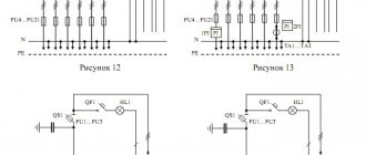
Installation of a TN-CS grounding system in a private house
When using this circuit it is very important to make a good individual ground loop
Please note that with the TN-CS system, protection against electric shock requires the installation of RCDs and breakers. Without them there is no talk of any protection.
Also, to ensure protection, it is necessary to connect all systems that are made of conductive materials - heating, water supply, foundation reinforcement frame, sewerage, gas pipeline (if they are made of metal pipes) to the earth bus with separate wires (inextricable). Therefore, the grounding bus must be taken “with a reserve”.
Scheme for converting the TN-C system to TN-C-S
To separate the PEN conductor and create grounding in a private house TN-CS, three buses are needed: on a metal base - this will be a PE (ground) bus, and on a dielectric base - this will be an N (neutral) bus, and a small splitter bus for four " seating places.
The metal “ground” bus must be attached to the metal body of the cabinet so that there is good electrical contact. To do this, at the fastening points, under the bolts, the paint is removed from the body to bare metal. The zero bus - on a dielectric base - is best mounted on a DIN rail. This installation method fulfills the basic requirement - after separation, the PE and N buses should not intersect anywhere (should not have contact).
Grounding in a private house - transition from the TN-C system to TN-C-S
Next we connect like this:
- The PEN conductor coming from the line is connected to the bus splitter.
- We connect the wire from the ground loop to the same bus.
- From one socket with a copper wire with a cross-section of 10 mm 2 we place a jumper on the ground bus;
- From the last free socket we place a jumper on the zero bus or neutral bus (also a 10 mm 2 copper wire).
Now that's it - grounding in a private house is done according to the TN-CS scheme. Next, to connect consumers, we take the phase from the input cable, zero from the N bus, and ground from the PE bus. We make sure that ground and zero do not intersect anywhere.
Grounding according to the TT system
Converting a TN-C circuit to TT is generally simple. There are two wires coming from the pole. The phase conductor is further used as a phase, and the protective PEN conductor is attached to the “zero” bus and is then considered zero. The conductor from the made circuit is directly supplied to the grounding bus.
Do-it-yourself grounding in a private house - TT diagram
The disadvantage of this system is that it provides protection only for equipment that requires the use of an “earth” wire. If there are also household appliances made using a two-wire circuit, they may be energized. Even if the housings are grounded with separate conductors, in case of problems, the voltage may remain at “zero” (the phase will be broken by the machine). Therefore, of these two schemes, TN-CS is preferred as it is more reliable.
Circuit design
Components
The previously mentioned grounding resistance (Rз) of the circuit is the main parameter controlled at all stages of its operation and determines the effectiveness of its use. This value must be so small as to provide a free path for the emergency current tending to flow into the ground.
Note! The most important factor that has a decisive influence on the value of grounding resistance is the quality and condition of the soil at the site of the installation.
Based on this, the charger in question or the ground loop of the charge circuit (which in our case is the same thing) must have a design that meets the following requirements:
- It must include a set of metal rods or pins with a length of at least 2 meters and a diameter of 10 to 25 millimeters;
- They are connected to each other (necessarily for welding) by plates of the same metal into a structure of a certain shape, forming a so-called “grounding conductor”;
- In addition, the device includes a supply copper busbar (also called electrical) with a cross-section determined by the type of equipment being protected and the magnitude of the drain current (see the table in the figure below).
Additional Information. Conventionally, this design includes connecting copper wires in the form of a bundle or braid.
These component devices are necessary to connect the elements of the protected equipment with the descent (copper busbar).
Differences in device location
According to the provisions of the PUE, the protective circuit can have both external and internal design, and each of them is subject to special requirements. The latter establishes not only the permissible resistance of the ground loop, but also stipulates the conditions for measuring this parameter in each particular case (outside and inside the object).
When dividing grounding systems according to their location, it should be remembered that only for external structures the question of how the grounding resistance is normalized is correct, since it is usually absent indoors. Internal structures are characterized by wiring of electrical busbars along the entire perimeter of the premises, to which grounded parts of equipment and devices are connected through flexible copper conductors.
For structural elements grounded outside the facility, the concept of re-grounding resistance is introduced, which appeared as a result of the special organization of protection at the substation. The fact is that when forming a neutral protective conductor or a working conductor combined with it at the supply station, the neutral point of the equipment (step-down transformer, in particular) is already grounded once.
Therefore, when another local grounding is made at the opposite end of the same wire (usually a PEN or PE bus connected directly to the consumer panel), it can rightfully be called repeated. The organization of this type of protection is shown in the figure below.
Important! The presence of local or repeated grounding allows you to insure yourself in case of damage to the protective neutral wire PEN (PE - in the TN-CS power supply system).
Such a malfunction is usually found in technical literature under the name “zero burnout.”
Is grounding necessary in a private house?
When using any electrical appliances in the house, there is always a risk of damaging the insulation of the wires or shorting them to the housing. In this case, any person touching the dangerous zone leads to electric shock, which can end tragically. The current always tends to the ground, and the human body becomes a conductor connecting the damaged device to the ground.
What does grounding do? Essentially, it is a system that provides the shortest path for electrical current. According to the law of physics, he selects the conductor with the lowest electrical resistance, and the circuit has this property. Almost all the current is directed to the ground electrode, and therefore only a small part of it will pass through the human body, which cannot cause harm. Thus, the ground loop ensures electrical safety. Regulatory documents (GOSTs, SNiP, PUE) indicate that any private, residential building must be equipped with it for alternating current networks with voltages above 40 V and alternating current networks with voltages above 100 V.
In addition to ensuring safety, the grounding system increases the reliability and durability of household appliances. It ensures stable operation of installations, protection against overvoltage and various network interferences, and reduces the impact of external sources of electromagnetic radiation.
Grounding should not be confused with lightning rods (lightning rods). Although the principle of their operation is similar, they perform different tasks. The job of a lightning rod is to divert lightning into the ground when it hits a house. In this case, a powerful electric charge arises, which should not enter the internal network, because can simply melt a wire or cable. That is why the lightning rod line runs from the receivers on the roof along the outer contour and should not be combined with the grounding, internal line. The lightning rod and grounding may have a common underground circuit (if it has a margin in cross-section), but the wiring must be separated.
Issues covered in the PUE
Regulation of the operating procedure for various types of protective systems can be presented in the form of a certain set of requirements relating to the arrangement of individual structures.
According to them, the functional readiness of grounding loops, which include a whole set of structural elements, must be confirmed by the following technical data:
- Description of the design and composition of protective devices used in existing electrical installations;
- Formulas for calculating their sizes, as well as the resistance standards of grounding devices (GD);
- Tables with correction factors that allow you to introduce corrections for the quality and condition of the soil at the location of the contour (taking into account the material of individual elements);
- The procedure for organizing and conducting control tests available for grounding systems.
On a note. The presence of documented data on the performance characteristics and reliability of the functioning of the grounding loop of a private house, for example, will eliminate the possibility of electric shock to animals and residents.
When installing it, you are required to act in strict accordance with the PUE, as well as comply with all requirements regarding the operation of this protective device.
Connection diagrams for voltage transformers in open and open delta
An open delta connection means that the equipment is connected between the sides of two phases. In this case, electric current is conducted from the outside, from the secondary windings of a number proportional to this indicator. The relay and the main load are connected between the secondary network, which allows you to obtain the desired level of resistance.
This circuit allows you to connect three sources at a time
Please note that the supply is organized in a linear manner, and it is necessary to avoid the passage of current from the first to the third source and vice versa
The open type of connection is used in rectifier equipment. Using a type connection, a current of triple frequency is achieved, which is impossible when working with a star or open symmetrical. An option is used when three transformers with one phase are connected to a device that increases proportionally the three operating frequencies.
The neutral of the primary winding must be grounded, and for the secondary winding, parameters of at least 100 Volts are selected, if grounded. For an isolated one, the coefficient is taken to be 100 to 3 V. The coefficient is three times, therefore, the secondary windings sum up the transformation coefficient also three times. Therefore, for the example described above, it is 6 thousand to one hundred to three. The peak is obtained from the transformer windings of the outer surface, since the supply is carried out through the secondary. Grounding is required.
On the contrary, there is a risk not for the device, but for the personnel who service it. In production, it is strictly prohibited to install protective or switching equipment between devices of this type.
General provisions of the grounding system in a private house (3 phase, 380 V)
According to the PUE (ed. 7), electrical installations with voltage up to 1 kV in relation to electrical safety measures are divided into:
- electrical installations in networks with a solidly grounded neutral;
- electrical installations in networks with isolated neutral.
An exposed
conductive part
is a conductive part of an electrical installation that is accessible to touch, not normally energized, but which may become energized if the main insulation is damaged.
For electrical installations with voltage up to 1 kV, the following designations are accepted:
- TN-CS - a TN system in which the functions of the zero protective PE and zero working N conductors are combined in one conductor in some part of it, starting from the power source (it can be obtained by making some changes to the TN-C);
- CT is a system in which the neutral of the power source is solidly grounded, and the exposed conductive parts of the electrical installation are grounded using a grounding device that is electrically independent from the solidly grounded neutral of the source (i.e., zero N and grounding PE are isolated from each other).
Designation of other systems
- TN - a system in which the neutral of the power source is solidly grounded, and the open conductive parts of the electrical installation are connected to the solidly grounded neutral of the source through neutral protective conductors;
- TN-C - a TN system in which the neutral protective and neutral working conductors are combined in one conductor along its entire length (most common in Russia);
- TN-S - TN system, in which the neutral protective and neutral working conductors are separated along its entire length;
- IT is a system in which the neutral of the power supply is isolated from earth or grounded through instruments or devices having high resistance, and the exposed conductive parts of the electrical installation are grounded.
Drawings of TN-C, TN-S, TN-CS systems
Decoding letter designations
Decoding of letter designations:
- The subsequent (after N) letters indicate the combination in one conductor or the separation of the functions of the zero working and zero protective conductors:
- S - zero working (N) and zero protective (PE) conductors are separated;
- C - the functions of the neutral protective and neutral working conductors are combined in one conductor (PEN conductor);
- The second letter is the state of open conductive parts relative to the ground:
- T - open conductive parts are grounded, regardless of the relation to the ground of the neutral of the power source or any point of the supply network;
- N - open conductive parts are connected to the solidly grounded neutral of the power source.
- The first letter is the state of the neutral of the power source relative to ground:
- T - grounded neutral;
- I - isolated neutral.
- N - zero working (neutral) conductor;
- PE - protective conductor (grounding conductor, neutral protective conductor, protective conductor of the potential equalization system);
- PEN - combined neutral protective and neutral working conductors.
What electrical characteristics ensure safe operation of the ground loop?
The protective function of the circuit is based on the phenomenon that fault current flows along the path of least resistance.
Due to damage to the insulation, a phase potential may appear on the body of any household appliance. In the old TN-C grounding system, it will flow through the body of the person who touches it.
The severity of an electrical injury depends on many factors, but can also lead to fatal consequences.
In the TN-S power supply circuit, an artificially created PE conductor through the grounding loop removes dangerous potential and protects a person from electric shock.
For optimal operation of the circuit, it is necessary to take into account:
- resistance to spreading;
- touch and step tension;
- soil condition based on its resistivity;
- electrical characteristics of selected materials and their resistance to aggressive soil environments;
- circuit design, which must be calculated according to standards and verified by electrical measurements with high-precision instruments.
Resistance of the grounding device in electrical installations up to 1000 V: what components does it consist of?
Any grounding loop consists of vertical or horizontal grounding conductors (electrodes) located in the ground. An emergency current flows through the contact they create.
Vertical electrodes are buried in the soil, spaced at a certain distance, and united by a horizontal ground electrode connected to the main busbar of the building.
For a private house, one vertical ground electrode is rarely used due to the resistance to current flow.
Let us assume that there is a structure with one vertical electrode connected to it, located in the soil. There is a metal short circuit to the main bus. For simplicity, we neglect the resistance of the grounding conductor.
The short circuit current begins to flow to the ground potential along the electrode and is distributed from it evenly in all directions. In this case, the maximum current density will be created at the ground electrode itself, and with distance from it it will begin to decrease.
The passage of current through an ever-increasing surface of the earth weakens its magnitude. Voltage also has the greatest value at the electrode, and with a constant decrease in the current value it drops. Here Ohm's simple law comes into play.
At the boundary of a certain area, called the spreading zone, the stress decreases to almost zero from its maximum value. In this way, we obtained points of zero potential located on opposite sides of the electrode, at which U=0.
The resistance of the grounding device Rз is the resistance of the land between the points of zero potential. It is calculated using the formula Rз=Uф/Iкз.
Its value is very little affected by the resistance of the metal parts of the grounding conductors with the busbar and the contacts of the electrodes with the ground - they are very small. The issue of reducing it is solved by changing the contour design and soil characteristics.
This indicator can be improved by installing an additional electrode. However, it must be mounted in a certain way.
If two electrodes are placed side by side, the area of the spreading zone remains virtually unchanged. The short circuit current flows into the same area of soil. Therefore, grounding conductors must be spaced over a greater distance.
In this case, the short-circuit current will flow from each electrode, dividing into two flows, and a space will form between them where they influence each other. This is called the shielding zone. To assess its characteristics, correction factors have been introduced.
The second method of improving the resistance of a grounding device is based on increasing the length of the vertical electrode and burying it in the ground to 30 meters. The technology of this method is given at the end of the article.
Several vertical electrodes are welded in the soil to a metal strip (horizontal ground electrode). It also affects the flow of emergency current and is assessed by an individual coefficient.
Its value depends on the number of electrodes in the circuit and the ratio of the distance between them to their length. The data is summarized in a table.
Thus, the electrical characteristics of the created circuit strongly depend on the configuration and location of vertical and horizontal ground electrodes and their penetration into the ground.
The owner of a private house needs to evaluate the resistance of the grounding device in electrical installations up to 1000 V and make a preliminary calculation on paper before starting to assemble the structure. To do this, you need to understand from which processes the parameters specified in the project are taken.
Touch and step voltage: what is it and how does it affect ground loop design
Touch voltage is described in clause PUE 1.7.24. Its value is included in the formulas for calculating the ground loop resistance.
Let’s imagine that a phase potential U appears on the body of some equipment and a person with body resistance R touches it.
Current It will begin to flow through it, which is determined by Ohm’s law. The magnitude of the applied voltage depends on the place where the contact is created, the distance from the maximum value of U, and is designated by the term touch (Upr).
Since human safety depends on Upr, strict standards have been introduced for it. When creating an electrical project for a facility, it is subject to strict restrictions that affect safety. They are taken into account in the permissible resistance parameters of the grounding device.
Step voltage
Another number of factors that influence the calculation of the circuit is taking into account those processes that occur directly on the ground during the flow of emergency current, distributed within the area where a person may accidentally find himself. They are taken into account by the step voltage.
At the epicenter of the discharge, the maximum voltage is applied, and its value gradually decreases with increasing distance to zero. When a person moves in this zone, a potential difference will arise between his legs.
It increases as you approach the discharge site, and under certain conditions can lead to electrical injury: the closer to the center, the more dangerous.
The step voltage term Ush is included in clause PUE 1.7.25. It is strictly standardized by the formulas for calculating the design of grounding devices.
At industrial facilities, expensive special protections are usually used that quickly turn off emergency modes when the step voltage has a very short time to manifest itself.
There are no such devices in a private home. Therefore, increased demands are placed on the quality of the circuit. The owner needs to consider its location and the route of the horizontal ground electrode.
The stress of touch and step is sought to be kept as minimal as possible to ensure increased human safety. They are taken into account by the PUE standards.
What standards for resistance to spreading are included in the PUE and why?
To create a reliable circuit for a private home, you should understand that it does not work on its own, but as part of the entire grounding system of an electrical installation, starting from an industrial transformer substation.
Safety depends on the type of neutral point of the transformer transformer and the speed of emergency response.
At industrial facilities that require prompt shutdown of emergencies, an effectively grounded neutral is created, which makes it possible to quickly shut down short-circuit currents in case of single-phase ground faults. To do this, its resistance, taking into account the influence of all natural and artificial grounding conductors, should not exceed 0.5 Ohm. (Clause 1.7.90.)
A household electrical network of 380/220 volts is usually created with a solidly grounded neutral. Its safety in some part can be improved by an isolation transformer.
A network with an isolated neutral is created behind it. But we are now considering another issue.
A transformer substation connected according to the usual circuit with a grounded neutral must operate in the mode provided for in clause PUE 1.7.101.
This means that when powering a private house with a voltage of 380/220 volts, the total resistance of the entire chain of grounding devices must fall within the standard of less than 4 ohms. This value is influenced by all repeated grounding of overhead lines and natural grounding.
The latter include reinforced concrete foundations of buildings and other metal structures buried in the ground. Their task is to provide long-term electrical contact with the ground.
Repeated line grounding conductors are distributed among overhead line supports to ensure a sufficient magnitude of single-phase fault current that the current protection must sense. They are placed at the entrance to the building.
All these groundings should collectively provide a resistance value of 0.4 Ohm at the transformer substation.
When overhead lines and transformer transformers are put into operation, then any grounding installed on them is in operation. It is impossible to measure its resistance separately and is very dangerous: it is part of the electrical circuit.
Now let's continue our consideration of paragraph PUE 1.7.107. for the grounding device of a private house. Other standards are already given here.
For the ground electrode we are creating, a value of 30 Ohms has been introduced. The ground loop can be disconnected from the main shield and its resistance can be measured. We understand that in operation it participates with all the repeated and natural grounding conductors of the circuit and provides 4 Ohms for the transformer at the transformer substation.
But it's not that simple. We will need to fulfill one more safety condition: the resistance of the nearest repeated grounding electrode must be 10 Ohms. This is stated in paragraph PUE 1.7.103.
However, providing these 10 and 30 Ohms in simple ways is not always possible due to the physical condition of the soil.
Types of soils and their resistivity: what requires mandatory consideration
Our circuit will be driven into the ground, which serves as a conductor of electric current. Its conductivity depends on many factors and is normalized by the resistivity value.
For example, rocky soil has very poor characteristics. Working on it is a bad idea. Standardized parameters and possible limits of their deviation are placed in the table.
This information is presented as indicative for making an approximate calculation. When creating a contour design, it is advisable to clarify them on a specific area.
The moister the soil and the more different salts it contains, the better its resistivity. However, salt solutions are an aggressive environment that causes corrosion of metals.
It is the constant fluctuations in moisture, depending on the time of year and weather conditions, that cause large deviations in resistivity from the average value.
In cold weather, water turns into ice, and it conducts electricity rather poorly. During hot weather, the soil dries out. Winter and summer are the most unfavorable periods for the operation of the ground loop.
Therefore, these seasons are used to carry out control measurements of spreading resistance.
The soil does not have a uniform structure. When going deep into the soil, all sorts of surprises can occur. It is impossible to foresee them. Especially at great depth.
For example, on top of the soil there may be a layer of black soil, and under it there may be loam or sandy loam, stones.
You can roughly estimate the composition of the soil yourself. To do this, they take a piece of it from a depth of about a meter and try to roll it into a “sausage” between their palms. If its thickness corresponds to a match, then it is clay.
You can't roll anything out of sand; it crumbles. You can make sausages about a centimeter thick from loam. The sandy loam rolls up into slightly larger pieces and immediately falls apart.
The method is approximate, but it allows you to obtain data for calculating the project. More accurately, these results are provided by instruments designed to measure the electrical resistance of soils. They are handled by specialists from electrical laboratories.
Since soil resistivity strongly depends on the season, for a more accurate calculation of the contour, seasonal coefficients have been introduced that also take into account the four areas of residence.
Requirements for materials for the ground loop that you must know
High-quality electrical contact between the metal of the electrodes and the soil is created not by burying the structure, but by driving the rods into the ground, when the soil is compacted when pressed.
The electrodes must be able to withstand mechanical shock loads well when installing the circuit, enter the soil without deformation, and maintain their electrical characteristics for decades when exposed to an aggressive soil environment.
The choice of grounding conductors is subject to strict standards regarding the type of metals and their dimensions. The maximum permissible minimum sizes of electrodes are published in the PUE table.
It is impossible to reduce the cross-section of materials, and choosing thicker ones is not rational.
For vertical grounding conductors, a pipe, rod and angle are usually used, and horizontal ones - the same strip or rod. Their cross-section must comply with the requirements of Table 1.7.104.
The design of the circuit is designed to create electrical contact with the ground even when the metal is corroded. It cannot be protected with paints.
The final assembly of the electrodes is carried out by welding, and its seam quickly rusts and collapses. Therefore, it must be covered with a protective layer of bitumen varnish.
The metal of the connecting strip, located in the open air, to which the outlet to the main protective bus is connected, also needs to be painted.
Ground connection diagram.
Grounding connection diagram - represents a graphically depicted connection of various electrical elements and conductors to ensure the safety of using the electrical network. Building a house from scratch is not at all easy. This work has several stages. One of them is a grounding scheme. According to GOSTs, any building must be equipped with it
Builders and owners of private houses should pay special attention to this issue. It depends on them how safe life in such a building will be.
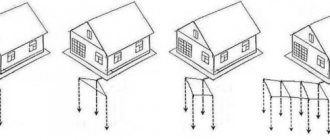
Any source of information about the grounding scheme will contain the depth to which it is done. It is 1.5 - 3 m. What do these numbers depend on? From two indicators: soil structure and groundwater depth. The higher the groundwater goes, the less depth is taken when grounding. When the water level is high, a small distance is also made between the electrodes. It is also necessary to take into account the composition of the soil, since chernozem peat and sandstone will have different levels of electrical conductivity. If you do not have special education, it is better to entrust the calculations of the grounding depth and the pitch between the electrodes to a specialist.
The current can be compared to the flow of water. And everyone knows that water always chooses the easier path. Therefore, if the devices malfunction, the current will flow not through the human body, possibly leading to death, but through the metal grounding loop. This happens because metal has greater electrical conductivity than the human body.
What does the circuit depend on?
Before starting work, it is necessary to take measurements and measure the resistance of the ground loop. This indicator depends on several factors, in particular:
- Condition of the ground flooring;
- Grounding installation depth;
- Soil quality and type (clay, black soil, sand, etc.);
- Number of grounding groups and electrodes in each group;
- Electrode material and its characteristics.
Ideally, you need to place the ground loop in black soil, clay soils and loams. It is strictly forbidden to install electrical resistance in stone covers or rocks; they also conduct current, and the resistance of these materials is very low.
Grounding soils
Selecting materials for pins (electrodes)
For pins, it is advisable to use rods Ø16 mm, angles 50x50x5 or thick-walled pipes 2.5-3 meters long. It is IMPOSSIBLE to use reinforcement due to the hardened surface and accelerated destruction in the ground.
Installation is carried out below the soil freezing level. The depth may vary in different regions, but usually it is 60-100 cm.
In dry soil, the pins are driven to such a depth that at least 1/3 of the length is in wet soil, which may require increasing the driving depth and length of the tubes. It is desirable to use pipes in arid regions:
- 1. the length of the pipe is selected so that after driving its end is at ground level;
- 2. the ends of the pipes are flattened;
- 3. 5-7 holes Ø10-12mm are drilled above the flattened end;
- 4. After installation is completed and when the grounding resistance increases, salt water is poured into the pipe.
For greater reliability, the pins are arranged in a triangle or square. They must be connected to each other using the same corners or a metal bus so that each of them is connected to the other two. Thus, if one of the jumpers fails, all grounding pins remain operational.
Differences between traditional and pin grounding
The traditional ground loop, which is usually installed independently, is a very bulky and labor-intensive underground structure.
Several vertical electrodes (angle, pipe, rod) are hammered in, a trench is dug between them, and they are all connected to each other by horizontal connections (tire or rod).
The distance between the vertical electrodes must be no less than their length. What's wrong with this method?
Firstly, few people want to dig up their plot with meter-long trenches, and if the territory has already been improved, then a deadlock situation generally arises. In addition, all these rusty metal corners, pipes and tires, being in the ground, after a few years of operation (literally within 5-7 years) begin to rapidly deteriorate.
Therefore, today another grounding system has become very popular, namely, modular pin or deep. The most famous manufacturing companies in our area are Galmar and ZandZ.
As is known, the resistance of the grounding device depends on:
soil type
time of year
electrode depths
Thus, if one electrode is driven to the maximum possible depth by gradually increasing it, then ideal resistance values can be obtained. Deep grounding works on this principle.
much more durable
much easier to install
and at the same time it is not so expensive (you can find kits for about 5,000 rubles)
Plus to all this, the entire installation is done without welding.
It is the need for welding that stops many people from doing this work themselves. Either there is no apparatus, or there are no necessary skills.
So you have to hire third-party electricians.
All grounding takes up space on the territory of your home, literally a few square centimeters.
And it can be done without any problems right in the basement of the building.
On average, it turns out that in a private house without a boiler, in order to achieve the required 30 Ohms, you will have to drive an electrode with a total length of 6-9 meters. For a house with gas heating (R=10 Ohm) - 9-15 meters.
These are averages. More accurate data is always individual and directly depends on the region where you live, the quality and composition of the soil.
If your house is built on sand, definitely buy a 15-meter kit. Even without a gas boiler.
The distance of the grounding route from the wall is also regulated. Unlike the input cable, it must be at least 1 meter.
For underground cable entry this figure is 0.6 m. Why so, read in detail about these and other requirements in a separate article.
Common mistakes when installing grounding
When installing grounding, inexperienced workers often make the following mistakes:
If, during driving, the pin entered the ground incorrectly, then it is prohibited to remove it by loosening it, because the likelihood of bending the element increases. A bent rod must not be used for grounding. Correctly remove the rod using a jack. If it is difficult to drive the electrode into the ground, choose another area. In fact, rods are not driven into rocky and dense rocks. In this case, holes are drilled and metal pipes are installed in them. To ensure that the entire surface of the electrode works correctly, it must be installed strictly vertically.
A common mistake is driving the pin unevenly (deviating from the vertical). When installing any grounding option, it is important to accurately calculate all the parameters and sizes of the components, because when adjusting the parts during the assembly process, deviations from the geometry and loose joints will appear, which will worsen the effectiveness of the grounding loop. To connect all network elements, only welding is used. This is the only way to achieve the required reliability.
Threaded connections can only be used when connecting a copper busbar. Moreover, a copper bolt is used for joining. If the grounding loop is made from the house at a distance of less than one meter, then all damp surfaces and even water flowing from the tap will be shocked. If you decide to use metal pins, then preference is given to galvanized elements that will last at least 10 years.
When arranging the grounding loop of a private house, it is important to comply with all regulatory requirements, choose the right circuit and calculate the network parameters. During installation, the design standards are strictly adhered to, and after assembly, the system is tested
Contour selection
Before calculating the circuit, you are given the opportunity to choose one of the following options for grounding devices:
- A triangular structure, the parameters of which are determined at the design stage.
- An extended linear structure mounted along the perimeter of the protected object.
- Modular pin grounding design.
Each of the above methods of assembly and subsequent installation of grounding devices requires detailed consideration.
Triangular design
This option for making a locking device is the most famous and widespread among professionals and amateurs. To arrange such a structure, you will need to prepare the following elements:
- Two-meter metal rods (reinforcing bars) in the amount of 3 pieces.
- The same number of steel jumpers designed to combine the rods into a single structure.
- A copper busbar required to connect the circuit breaker with the point of collection of conductors from the grounded equipment in the distribution cabinet (GZSh - main grounding busbar).
The plane of the welded contour with the pins already driven into the ground when arranging the charger should be located at a depth of approximately 30-60 cm.
Linear outline
Linear grounding is selected when it is necessary to connect several pieces of equipment located at a distance from one another to a protective structure. It consists of several pins (3) driven into the ground, the location of which relative to each other is selected from the calculated data.
Linear diagram of a ground loop for a private house
From the structure assembled according to this scheme, as in the case of a triangle, a branch (2) is made towards the distribution panel with the main shield. Before calculating such a circuit breaker, it should be taken into account that the total number of pins is limited by the mutual influence of emergency currents flowing in each single ground electrode.
Modular-pin grounding
The modular type of charger is used in situations where the area on the site in front of the house is limited in size and a single pin structure is allowed.
Installation diagram of a single grounding electrode
It contains the following elements in its kit:
- One and a half meter long steel rod with copper coating and available on
- working part threaded.
- A special coupling made of brass, providing a threaded connection of a vertically driven pin with a grounding tap.
- Brass clamps of a special design, guaranteeing reliable connection of the metal pins with the connecting strip.
- Tips for the ground rods themselves.
- An attachment with an impact platform that allows you to transmit impulse from a driving tool (vibratory hammer).
Modular-pin grounding kit
Please note: For reliable protection against corrosion, all threaded elements of the rods are coated with graphite paste, included in the original delivery set.
The protective lubricant lasts for a long time and does not spread when the pins and other elements of such a charger are heated. The anti-corrosion tape included in the composition is resistant to aggressive environments and protects the entire structure from destruction.
Read more about installing modular pin grounding on this page.
Types of ground electrodes
It has already been repeatedly noted above that ground electrodes are used to drain current - metal electrodes that are in direct electrical contact with the ground.
There are natural and artificial grounding systems. As a first, it is allowed to use:
- metal parts of buildings, provided there is low resistance at the points of their contact with the ground;
- casing pipes;
- underground parts of utility lines built of metal;
- steel sheet piles for hydraulic structures;
- armored casings of underground cables.
Use as natural grounding is not allowed:
- utility lines used for pumping flammable materials;
- pipelines that have anti-corrosion insulation;
- central heating pipelines;
- sewer pipes.
If it is not possible to connect to one of the natural protective structures, then you will have to resort to the help of artificial grounding conductors. Unlike natural structures, they are installed specifically. To do this, they drive into the ground or lay at a certain depth:
- structural steel pipes with a diameter of 25–62 mm and a length of 2–3 m;
- steel corners with shelves no less than 50x50 mm;
- metal rods with a diameter of 10–12 mm;
- strip or tire steel, provided that its cross-section exceeds 1.5 cm2.
The surface of the electrodes should be as smooth as possible - this is necessary in order to achieve maximum contact with the ground. It is impossible to completely protect grounding from the harmful effects of corrosion. Destruction can be partially prevented in two ways - by using a protective coating with anti-corrosion conductive compounds or by choosing copper-plated or galvanized rolled steel as electrodes.
Installation of contact line circuit/shield
Using electric welding, connect the conductor wire to the ground loop. It is possible to create a contact in any plane and on any part of the triangle; contact at one of its vertices is considered optimal. A wire or strip of sheet steel is laid in trenches and brought to the electrical panel. At the end of the conductor connected to the shield, an M8 or M6 bolt is welded, forming a fastening unit.
Professional electricians note the higher efficiency of sheet steel as a conductor connection due to the larger area of contact with the ground. However, being more ductile, the wire is easier in terms of forming angular transitions. To create bends on a steel strip, it is necessary to use a gas burner; “cold” deformation of the material is not allowed.
Thermal impact points must be cleaned and treated with an anti-corrosion compound; no treatment of the contact surface is required. There must be good contact between the circuit/panel connection line and the ground, otherwise the grounding system will be ineffective.
After processing the welded units and areas treated with a gas torch, the contact line, immersed in the trench, is covered with soil. If there are areas in the open air, they may be painted. From the contact line of the grounding loop, a line can be laid connecting the grounding system and the lightning rod.
Main ground bus
According to clause 1.7.121 of the PUE, the following can be used as PE conductors in electrical installations with voltage up to 1 kV:
- specially provided conductors:
- cores of multi-core cables;
- insulated or non-insulated wires in a common sheath with phase wires;
- permanently laid insulated or non-insulated conductors;
- exposed conductive parts of electrical installations:
- aluminum cable sheaths;
- steel pipes for electrical wiring;
- metal shells and supporting structures of busbars and complete devices of factory production (provided that the design of the boxes and trays provides for such use, as indicated in the manufacturer’s documentation, and their location excludes the possibility of mechanical damage);
- Some third party conductive parts:
- metal building structures of buildings and structures (trusses, columns, etc.);
- reinforcement of reinforced concrete building structures, subject to the requirements of 1.7.122;
- metal structures for industrial purposes (crane rails, galleries, platforms, elevator shafts, lifts, elevators, channel frames, etc.).
P. 1.7.122. The use of exposed and third-party conductive parts as PE conductors is permitted if they meet the requirements of this chapter for conductivity and continuity of the electrical circuit.
More details
Third-party conductive parts can be used as PE conductors if they also simultaneously meet the following requirements:
- the continuity of the electrical circuit is ensured either by their design or by appropriate connections protected from mechanical, chemical and other damage;
- their dismantling is impossible unless measures are taken to maintain the continuity of the circuit and its conductivity.
The following are not allowed to be used as PE conductors:
- metal shells of insulating tubes and tubular wires, supporting cables for cable wiring, metal hoses, as well as lead sheaths of wires and cables;
- gas supply pipelines and other pipelines of flammable and explosive substances and mixtures, sewerage and central heating pipes;
- water pipes with insulating inserts.
Neutral protective conductors of circuits are not allowed to be used as neutral protective conductors of electrical equipment powered by other circuits, and also to use open conductive parts of electrical equipment as neutral protective conductors for other electrical equipment, with the exception of shells and supporting structures of busbars and complete factory-made devices that provide the possibility connecting protective conductors to them in the right place.
The use of specially designed protective conductors for other purposes is not permitted.
The main grounding bus can be made inside the input device of an electrical installation with voltage up to 1 kV or separately from it (clause 1.7.119. PUE).
Inside the input device, a PE bus should be used as the main grounding bus.
When installed separately, the main grounding bus must be located in an accessible, convenient place for maintenance near the input device.
The cross-section of a separately installed main grounding bus must be no less than the cross-section of the PE (PEN) conductor of the supply line.
The main grounding bus should, as a rule, be copper. It is allowed to use a main grounding bus made of steel. The use of aluminum tires is not permitted.
The design of the bus must provide for the possibility of individual disconnection of the conductors connected to it. Disconnection must only be possible using a tool.
Third-party conductive parts may be used to connect multiple main ground bars if they meet the electrical continuity and conductivity requirements of 1.7.122.
Grounding schemes for a private house
There are several grounding schemes in an individual cottage: TN-C, TN-CS and TN-S. The first letter in the abbreviation indicates the method of connecting the “ground” to the power source, the second deciphers the characteristics of the consumer.
TN-C circuit
This convenient variety is distinguished by the fact that the conductor simultaneously performs the functions of protection and a working device. This option is often used in old houses due to its ease of implementation and cost-effectiveness. However, due to the lack of a separate protection circuit during an accident, there is a possibility of a short circuit. In modern cottages this option is not used because it does not meet regulatory requirements.
TN-S circuit
In this circuit, separated conductors are used. In an emergency, no voltage is released to the body of the household appliance. This option is considered the safest because it protects against electric shock. However, to implement such a scheme you need to put in a lot of effort and spend additional money.
TN-CS circuit
This is a combined version in which two conductors coming from the power source are combined into one. In this case, an additional PE type protective conductor is installed at the entrance to the house. This scheme is recommended to be used as the main model in buildings for any purpose, including private houses. Its advantages are reliability and ease of assembly. Thanks to the use of an additional conductor, the likelihood of a fire during a short circuit is minimal.
Design and types of circuits
The standard ground loop is made not only in the form of a triangle, which is optimal for most conditions; it can be in the shape of a line, a rectangle, an angle, or even an arc (oval). When considering each of these structures from the point of view of their resistance, the following should be noted:
- The basis of the design is pins or rods driven into the ground;
- They are connected to each other by metal strips cut to length (the so-called “metal bond”);
- A copper busbar is welded to one of the pins or to a strip of metal, laid in a separate groove, as shown in the figure below.
The choice of a triangle as the main type of ground electrode is explained by the fact that in this case it is possible to obtain the maximum dispersion zone with a small occupied area. The material costs for such a structure are minimal, and the resistance to spreading in the ground, if properly constructed, complies with the standards.
The distance between the pins of a triangular contour is usually chosen equal to the length, and the maximum distance from one to the other can be twice as large. So, if the pins are buried 250 centimeters into the ground, it can reach 5 meters. Only if these conditions are met is it possible to obtain optimal characteristics of a structure buried in the ground.
The linear contour is a chain of pins driven into the ground at a certain pitch of approximately 5-10 meters (see the figure below).
In some cases, depending on terrain conditions, the structure is constructed in the form of a semicircle; in this case, the pins are located at the same distance from one another. In such a distributed device, the resistance should be minimal precisely at the points of contact of the rods with the ground. To achieve the required R3 value, as many pins as possible are hammered in.
All other types of structures are modifications of the ground electrodes described above, and the requirements for drainage resistance are derived from those already considered.
What is grounding: a little theory
Before we start building grounding, let's figure out what it is and how it works. Standard voltage is supplied to household consumers in two ways - through two or four wires. In the first case, there is a voltage of 220 V between the so-called phase and neutral conductors - such a network is called single-phase. In the second case, we are dealing with a three-phase network, in which electricity is transmitted by three phases and one zero. The potential between adjacent phases is 380 V, while the voltage between the neutral conductor and each phase is 220 V.
The diagram for connecting a house to a 220 V network with a ground loop is called single-phase
The neutral wire is often called “ground” and for good reason. The fact is that it has a direct connection with the surface of our planet, as a result of which the potential between them is zero. If for some reason the connection to the neutral wire disappears, then a person can become a conductor of electricity. Getting under the reference voltage is deadly, so scientists have come up with a way to send the current along a different path. To do this, the housing of modern electrical appliances is connected to a device that has good contact with the ground. According to standards, its resistance should not exceed 4 ohms, while our body has a resistance of 100,000–500,000 ohms. Naturally, in this case, the current will flow along the path of minimal resistance and the person will be safe.
To connect the cottage to a three-phase network, four wires are used
The device mentioned above is called a protective ground loop. Thanks to him it is possible to:
- reduce the risk of electric shock;
- avoid damage to household appliances when the zero line breaks;
- reduce the level of electromagnetic interference emanating from household electrical equipment and wiring;
- smooth out noise interference present in electrical networks.
Grounding circuits are not arranged arbitrarily, but in strict accordance with the following regulatory documents:
- Safety regulations for the operation of electrical installations (PTBE).
- Rules for the construction of consumer electrical installations (PUE).
- Rules for the technical operation of consumer electrical installations (PTEE).
After reading all three documents, you will not find any mention anywhere that only qualified representatives of energy supply organizations are allowed to install grounding loops. Accordingly, work to ensure electrical safety can be done independently. The main thing is that the grounding circuit is built according to all the rules and complies with accepted standards.
Installation steps
You can make a triangle grounding using the following step-by-step instructions:
- At the selected location we mark the places where vertical electrodes will be buried. Then you need to dig a trench up to one meter deep. The depth should be below freezing of the ground. The lines of the structure must form a triangle, the length of the side of which is indicated in the calculations.
- Then you need to dig a trench from the structure to the power panel. The corner of the circuit to which the shield will be connected is selected as the closest one. This is done to save materials.
- Next, you need to drive the electrodes into the ground, leaving 20 cm above the ground.
- Using a steel strip it is necessary to create a closed system. It is welded to the electrodes and forms a triangle.
- A strip is laid from the nearest point to the power panel and displayed on the wall.
- Weld a bolt to the strip connected to the cabinet, with its thread facing outward. This means that the head of the bolt will be welded. To connect the grounding to the panel in the house, it is important to drill a hole in the wall in advance for the grounding cable.
- Using a nut, the grounding cable is attached to the bolt. After this, it is necessary to treat the welds and joints with special anti-corrosion substances and sealant.
The instructions in pictures are as follows:
The final stage of installing a ground electrode yourself will be checking the grounding resistance. To do this, you need to have a special electrical device called an ohmmeter. But since such a device is not cheap, it is better to invite a specialist from the energy management. The specialist needs to take measurements and enter data into the grounding circuit passport.
It is important to check in dry weather, since atmospheric moisture can cause measurement errors. The circuit resistance standard should not exceed 4 Ohms for a 220 Volt network. If the resistance exceeds this indicator, then the grounding needs to be modified. To do this, you need to add another grounding conductor or make a diamond-shaped structure.
If the parameters meet all standards and requirements and the low resistance of the circuit is confirmed, then the trench can be buried. This is done with homogeneous soil, without crushed stone and debris. The grounding should be connected to the panel not in parallel, but separately for each technical unit.
There is another way to check resistance without calling a specialist. To do this, it is enough to have a lamp with a power of at least 100 W. The light source is connected to the system with one contact, and to the phase with the second. If the triangle is installed correctly, the light will glow brightly. If it shines dimly, it means the contacts between the ground electrodes are weak and the joints will need to be redone. If the light does not come on at all, then the triangle is not installed correctly. In this case, you should check the diagram itself and see where the error was made.
The video below clearly shows how to assemble a triangular-shaped ground loop:
That's all I wanted to tell you about how to make triangle grounding with your own hands. We hope the provided diagrams, photos and installation instructions were useful to you!
It will be useful to read:
The procedure for arrangement and operation of protective electrical devices is regulated by the main provisions of the PUE approved by the Ministry of Economic Development, in accordance with the order dated July 8, 2002. Currently, the seventh edition of these standards has been prepared, which applies to all electrical equipment, including the grounding loop (see figure below).
To obtain complete information about the requirements for electrical installations and protective systems, let us consider their specific content using the example of an existing ground loop. The PUE standards for this type of device mainly concern such an important parameter as grounding resistance.
METHODS OF CONSTRUCTING THE EXTERNAL LOOP
Depending on the configuration and type of grounding electrode, there are two main methods of installing protective grounding: traditional and deep. In the first case, a home-made welded structure of several (most often three) vertical elements with an even and identical cross-section is laid in the ground.
An equilateral triangle is recognized as the optimal scheme; preference is given to long supports that are as far apart as possible from each other.
Installation of such a grounding device is carried out using:
- vibrating hammers used for driving pipe, angle or profiled steel;
- hand tools (sledgehammers or clamps);
- drilling devices with clamps, optimal for screwing in round rods.
The advantages of the traditional method of arranging protective grounding include a relatively low cost estimate, ease of installation and the ability to do the work yourself. The disadvantages are associated with the proximity to the zero level and the placement of welded structures in the ground; the method is considered insufficiently reliable and safe.
Separate requirements are put forward for the location of the electrodes; the fewer people there are in this area, the better. The northern (shady) side is considered optimal, as it is more damp.
The deep installation method involves laying vertical electrodes (modules) to a depth of 15-30 m. There are no welded joints; elements about 1.5 m long are connected by threaded couplings with conductive lubricant and deepened using vibrating hammers with an impact energy of up to 20-25 J.
The configuration of the grounding rod depends on the parameters of the site and the type of object; for residential buildings, one rod is more than enough.
The advantages of this method include the factory quality of the modules, the absence of labor-intensive excavation work and the possibility of installing protective grounding in basements or inside the perimeter of the house.
Installation is carried out in any weather conditions (if desired and equipment is available - on your own), the only disadvantage is the high cost of the device itself. During the work, the pins are protected from bending, and the threaded connections are periodically tightened.
The need for alternative options and additional measures arises when installing grounding in rocky, leached or dry areas. If it is impossible to reduce the resistivity of soils or lay vertical rods longer than 1 mm, electrolytic grounding is recognized as a reasonable alternative.
The essence of this method is to place an L-shaped perforated ground electrode filled with a mixture of mineral salts next to the object.
Connection to the remaining elements occurs according to the standard scheme, the estimated service life of the system is 50 years. Salts are renewed every 10 years; the disadvantages of this method include the high cost and the negative impact of minerals on foundation structures. But in areas with permafrost, this method is considered more profitable than laying rods to the depth of non-freezing reservoirs or installing complex structures.
Preparing the site for the ground electrode
It is advisable to do grounding in the wettest place of the site. It's better on the north side of the house, it's more humid there.
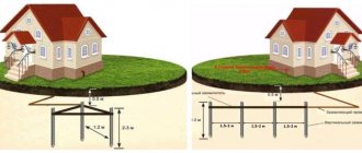
A trench is dug in the ground in the shape of a triangle and from the top of the triangle the trench is dripped towards the house. The depth of the trenches is 50-70 cm. The distance from the house to the ground electrode is 2-5 meters. Less is better.
Ground loop calculation
Traditionally, grounding electrodes are located in a line, but there are other options: triangle, square, etc. And a grounding device is sometimes called a loop because they were placed along the perimeter of the building, surrounded by a connection with several inputs to the internal loop - a steel strip already inside the building. Therefore, the contour is a historical name.
But it is not at all necessary to completely surround the house; it is enough to choose the direction for linear placement of electrodes or determine the area for some “cluster” option, where there is no interference and no excavation work is planned
A convenient location is important to avoid difficulties when entering the switchboard
A multi-level scheme is used for calculations; simply the parameters of materials and resistance values are not enough for the final result. Some of them simply depend on the specific situation. For example, from the choice of materials. What to make it from? From what is available, in order to buy less. If you immediately focus “through the store”, then proceed from the price-quality conditions. The main thing is that the material and parameters for each element of the grounding device correspond to the values given in the table. If the grounding device is assembled not from a construction kit, but from more affordable materials, then you next need to ask:
- Depth of immersion of grounding electrodes. Their length must be within reasonable limits. No less than the depth of soil freezing, but also commensurate with available means for driving.
- The distance between them. It must be a multiple of their length in order to be able to apply the coefficients of mutual influence - shielding - to the calculations.
- Number of electrodes. Although the calculation needs to include not only the quantity, but also the length of the strip that connects them and the entry into the house.
That is, in essence, the circuit is completely formed, and then its resistance is calculated. If it meets the standards, then we accept these parameters for manufacturing the device. If not, we change some to improve the characteristics.
Having such initial data, first of all we calculate the resistance of single grounding electrodes.
For all their complexity, the formulas for different types of grounding conductors are also different: their own for round sections, angles and strips. Also, for the calculation, you will have to select the coefficients of mutual influence of the electrodes corresponding to the initial data. After this, we substitute the values into the general formula:
- Where Rg is the calculated resistance of the horizontal ground electrode.
- Rв is the calculated resistance of the vertical ground electrode.
- Nв – number of vertical grounding conductors.
- ng – shielding coefficient of horizontal grounding conductors.
- nв – shielding coefficient of vertical grounding conductors.
We calculate the resistance of the grounding device. If the result is not satisfactory, you can change something in the source data. For example, add or, conversely, remove extra grounding electrodes. But, as soon as their number or length changes, either the length of the horizontal connection, or the mutual influence coefficient, or all together automatically changes. Additionally, the distance between the electrodes may change to maintain a multiple of the length. Therefore, the entire calculation starts from the beginning. As you can see, the process is relatively complicated.
However, you can use online calculators. And to convince yourself that the calculation is correct, compare the indicators of several. Moreover, there is already an idea: what, how and why, and this is already an advantage. After the calculations, you can proceed directly to installation.
What does grounding consist of?
- External ground loop. It is located outside the premises, directly in the ground. It is a spatial structure of electrodes (grounding conductors) connected to each other by an inseparable conductor.
- Internal ground loop. A conductive bus located inside a building. Covers the perimeter of each room. All electrical installations are connected to this device. Instead of an internal circuit, a grounding shield can be installed.
- Grounding conductors. Connecting lines designed to connect electrical installations directly to the ground electrode, or internal ground loop.
Take a closer look at these components.
External or outer contour
The installation of the ground loop depends on external conditions. Before starting the calculation and completing the design drawing, you need to know the parameters of the soil in which the ground electrodes will be installed. If you have built a house yourself, these characteristics are known. Otherwise, it is better to call surveyors to obtain an opinion on the soil.
What types of soils are there, and how do they affect the quality of grounding? Approximate resistivity of each soil type. The lower it is, the better the conductivity.
- Plastic clay, peat = 20–30 Ωm m
- Plastic loam, ash soils, ash, classic garden soil = 30–40 Ohm m
- Chernozem, shales, semi-hard clay = 50–60 Ohm m
This is the best environment to install an external ground loop. The current flow resistance will be quite low even with low moisture content. And in these soils the natural humidity is usually above average.
Semi-solid loam, mixture of clay and sand, wet sandy loam - 100–150 Ohm m
The resistance is slightly higher, but at normal humidity the grounding parameters will not exceed the standards. If there is prolonged dry weather in the installation region, it is necessary to take measures to forcibly moisten the installation sites of ground electrodes.
Clay gravel, sandy loam, wet (constant) sand = 300–500 Ohm m
Gravel, rock, dry sand - even with high general humidity, grounding in such soil will be ineffective. To comply with standards, deep grounding will have to be installed.
Many facility owners, saving on matches, simply do not understand why a grounding loop is needed. Its task, when connecting a phase to the ground, is to ensure the maximum value of the short circuit current. Only in this case will the protective shutdown devices operate quickly. This cannot be achieved if the current flow resistance is high.
Having decided on the soil, you can choose the type, and most importantly, the size of the ground electrodes. Preliminary calculation of parameters can be performed using the formula:
The calculation is given for vertically installed grounding conductors.
Decoding the formula values:
- R0 is the resistance of one ground electrode (electrode) obtained after calculation in ohms.
- Rekv - soil resistivity, see information above.
- L is the total length of each electrode in the circuit.
- d is the diameter of the electrode (if the cross-section is circular).
- T is the calculated distance from the center of the electrode to the surface of the earth.
By setting known data, as well as changing the ratio of values, you should achieve a value for one electrode of the order of 30 Ohms.
If the installation of vertical grounding electrodes is not possible (due to the quality of the soil), the resistance value of horizontal grounding electrodes can be calculated.
Therefore, it is better to spend more time driving vertical rods than to monitor the barometer and air humidity.
And yet we present the formula for calculating horizontal grounding conductors.
Accordingly, decoding of additional quantities:
- Rв is the resistance of one ground electrode (electrode) obtained after calculation in ohms.
- b - width of the electrode - grounding conductor.
- ψ is a coefficient depending on the weather season. The data can be taken in the table:
ɳG is the so-called demand coefficient for horizontally located electrodes. Without going into details, we get the numbers from the table in the illustration:
Preliminary calculation of resistance is necessary not only for proper planning of material purchases: although it will be a shame if you don’t have enough electrode to complete the work, and the store is several tens of kilometers away. A more or less neatly drawn up plan, calculations and drawings will be useful for resolving bureaucratic issues: when signing documents on acceptance of an object, or drawing up technical specifications with an energy sales company.
Of course, no engineer will sign papers only on the basis of even beautifully executed drawings. Spread resistance measurements will be taken.
How to install a ground loop yourself
You can do the grounding installation yourself. All steps will be described below.
Choosing a place
It should be located in that part of the site near the house where people and pets do not enter unless absolutely necessary. The contour is located no closer than 1 m from the foundation of the building. It is better if this area is surrounded by a low fence. All electrode locations are marked on the ground. Usually a regular, isosceles triangle is constructed.
Excavation
A trench 0.5-0.6 m deep is dug along the entire marking. A similar trench is dug along the course of laying the busbar connecting the circuit to the input electrical cabinet.
Assembling the structure
First, according to the diagram, the pins are driven in to a given depth (usually 2-2.5 m). A metal bond is welded to the tops of the rods. One strip is welded to the outermost electrode (the top of the triangle) and laid in a trench leading to the house.
Entering the house
The bus from the circuit is inserted into the input electrical panel. A hole is drilled at the end for a bolted connection. The corresponding cable core is connected here. With a TN-CS system, the busbar is connected to a splitter busbar.
Features of the grounding system and materials used
For each element of the grounding loop, the following materials are used:
- metal corner (steel) 50*50*5 mm – optimally suited for assembling the vertical part;
- sheet steel, chopped into strips measuring 40 * 4 mm, is used for horizontal grounding lines;
- steel wire with a diameter of 8 or 10 mm - used to connect the ground loop to the electrical panel.
Details regarding the dimensions and material of the grounding system elements are available in section 1.7, 7th edition of the PUE. It is strictly forbidden to use hardened steel reinforcement to build grounding structures. This material has a heterogeneous structure, which affects the distribution of current, and it is also more sensitive to corrosion.
For laying grounding lines, the optimal distance from the foundation is 1 meter. Externally, the contour is represented by an isosceles triangle; accordingly, this geometric figure is used when marking the site. Ground markings are made along the perimeter of the house at an appropriate distance. To indicate working lines, it is permissible to use serifs or stretch threads along driven stakes.