To create good and reliable grounding in a private home, there is a very simple and easy-to-implement solution that guarantees results for a hundred years. This is the installation of house grounding using a ready-made, quickly assembled ZANDZ grounding kit (pr. Russia), designed specifically for this application.
Advantages
The main element of any grounding device is the ground electrode, which is a metal structure mounted in the ground. The ZANDZ grounding electrode, obtained from the “Grounding in a private house” kit, is a single prefabricated deep grounding electrode, consisting of four 1.5-meter steel pins coated with a layer of electrical copper.
The advantages of this design and the materials used:
- Service life up to 100 years
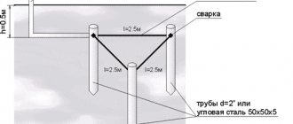
- Easy installation by one person without special tools. To build a ground electrode of the required length, 1.5-meter pins are buried into the ground one after another using a hand-held impact tool ( sledgehammer ). A bolt clamp is used to connect the conductor to the electrical panel.
- The minimum area occupied by the ground electrode allows it to be installed in the basements of houses, or close to walls in the form of just one point. Compactness minimizes required excavation work.
- No welding required*
- The quality of grounding does not depend on the weather and time of year
* The connection of elements of grounding devices NOT made of ferrous metals is permitted by technical circular 11/2006 of the RosElectroMontazh association (link to document)
Grounding. What is it and how to make it (part 3)
1 part. Grounding (general information, terms and definitions)
Part 2. Traditional methods of constructing grounding devices (description, calculation, installation)
Part 3. Modern methods of constructing grounding devices (description, calculation, installation)
In this part, I will talk about modern methods of constructing ground electrodes, which have the advantages of traditional construction methods and are devoid of their disadvantages.
D. Basic construction methods
D1. Modular grounding (for ordinary soils)
D1.1. Features of the solution
D1.1.1. Versatility and ease of use D1.1.2. Long service life D1.1.3. Dependence of a decrease in grounding resistance on an increase in electrode depth D1.1.4. Super compact D1.1.5. No welding
D1.2. Calculation of the resulting grounding resistance D1.3. Installation D1.4. Advantages and disadvantages
D 2. Electrolytic grounding (for permafrost or rocky soils)
D2.1. Features of the solution
D2.1.1. Ease of use in permafrost or rocky soils D2.1.2. Compactness D2.1.3. Talik formation D2.1.4. No welding
D2.2. Calculation of the resulting grounding resistance D2.3. Installation D2.4. Advantages and disadvantages
D. Basic construction methods
Let me remind you about the advantages and disadvantages of traditional methods of constructing ground electrodes, described in the last part:
| Several short electrodes (section D1.4 ) Advantages:
Flaws:
| Single depth electrode (section G2.4 ) Advantages:
Flaws:
|
I settled on general words:
At the end of the twentieth century, a solution was developed that has the advantages of both methods described above, without having their inherent disadvantages.
In addition, the strong influence of soil salinization on reducing grounding resistance (section D1.5.) attracted the attention of engineers so much that a “cure” was found for the shortcomings of this method - leaching of salt from the soil and corrosion of electrodes. It gave rise to a very interesting method of constructing a ground electrode, applicable even where simple metal electrodes fail - in permafrost and rocky soils.
D1. Modular grounding (for ordinary soils)
An ideal combination of the above-described properties of construction methods would be some method that has the following set:
Advantages:
- simplicity
- low cost of materials and installation
- availability of materials and installation
- high efficiency
- compactness
- seasonal INDEPENDENCE of grounding quality
Flaws:
- No
Alas, miracles do not happen! However, what we would like:
- reduce the length (depth) of the mounted grounding electrodes for the convenience of their manual installation (so as not to hammer these electrodes from the stepladder)
- leave a large length (depth) of the grounding electrodes
- remove the rig
- remove the sledgehammer
- remove welding
- increase the service life of electrodes without increasing the size to... well, let it be 100 years
- maintain adequate cost of materials.
A little fantastic, but the solution turned out to be simple: a technology called “modular pin grounding”, abbreviated as “modular grounding”.
With this method of construction, a grounding electrode of the required length (depth) is a prefabricated structure of several short (1.5 meters) steel pins - modules having small transverse dimensions (diameter less than 20 mm) with zinc or copper coating, which are connected in series one after another
. For deepening, an ordinary household electric jackhammer with sufficient impact energy is used.
As in the case of the “casing pipe” (p.), a large contact area of the ground electrode with the soil is achieved by a large length (depth) of the electrode. Due to reaching deep layers of soil, which in most cases have lower electrical resistivity, this method has greater efficiency (lower grounding resistance).
The pins can be connected to each other in several ways:
- "blind hole + spike"
. On one side of the pin there is a blind hole 50-70 mm deep, and on the other side there is a tenon 50-70 mm long, with a diameter slightly larger than the groove. During installation, the tenon is pressed into the hole. - "blind hole + pin + blind hole"
.
The pin has a blind hole on both sides with a depth of 50-70 mm. A pin 100-140 mm long is used as a separate additional part. During installation, it is inserted between the pins and pressed into both holes. It is considered a very unreliable connection method. - "thread + coupling + thread"
.
The pin has a 50 mm long thread on both sides. A coupling, a piece of pipe with an internal thread, is used as a separate additional part. During installation, it is screwed onto the recessed pin, after which the next pin is screwed into it. As many years of practice have shown, this is the most reliable connection method, allowing the installation of prefabricated grounding electrodes up to 40 meters deep with guaranteed preservation of the necessary electrical and anti-corrosion properties along all lengths.
This depth is a compromise between the maximum impact energy of the jackhammer, the friction force between the mounted electrode and the ground, and the mechanical strength of the coupling (its cost). Without increasing the impact energy, it is impossible to further deepen the electrode due to the friction force. As the impact energy increases, it is necessary to increase the strength of the coupling, which causes an increase in its cost.
D1.1. Features of the solution. Anti-corrosion properties.
D1.1.1. Versatility and ease of use
This solution can be called a “constructor”, because
Any necessary structure is assembled from standardized elements. For example, a depth electrode for 30 meters. All parts are industrially produced, which eliminates the need to “finish” anything on site. At the same time, they have the same quality and identical properties, which plays a role when carrying out a large volume of installation work on many similar objects, and also has a positive effect on the predictability of the results. Handling the pins is easier because they are only 1.5 meters long and weigh no more than 3 kilograms. This allows them to be transported in a small car.
D1.1.2. Long service life
Coating a steel pin with a layer of zinc or copper increases its service life up to several times (relative to the service life of a pin of the same size without coating).
The methods used to protect steel from corrosion by coatings vary greatly due to the different participation of these metals in electrochemical reactions, which have the most destructive effect on the pin. Due to the difference in these reactions, the difference in production, the difference in production costs, there is constant debate about which coating is better.
Zinc coating
In the zinc-iron pair, zinc is a reducing agent/donor (wiki). It is the zinc that oxidizes/corrodes first, thus protecting the iron.When its entire mass takes part in the reaction (oxidizes), the steel will begin to corrode.
Advantages:
- no need for mechanical protection of the coating during installation. Damage to the integrity of the coating does not lead to consequences, because zinc still protects iron by being nearby.
- cheap, well-established and widespread production of galvanized products with a coating thickness standard for this material from 5 to 30 microns (“hot” and “cold” galvanizing)
- anti-corrosion protection not only for pins, but also for all metal structures in the affected area. However, these metal structures most often do not need such protection.
Flaws:
- a relatively small increase in the service life of the pin due to the small thickness of the coating - up to 15-25 years.
- A thick layer of zinc coating has a high cost. In addition, it is very rare to find a production facility that has the technical ability to do this.
- reduction in the service life of pins in the presence of a large number of metal structures located next to them
Copper plating
In a copper-iron pair, copper is the oxidizing agent and iron is the reducing agent/donor (wiki). Iron is the first to oxidize/corrode, thus protecting copper.Strange... we need the opposite action.
But here lies the peculiarity of the electrochemical reaction: it is possible only in the presence of an electrolyte/water. If iron is isolated from it, the reaction stops.
Therefore, the copper coating must be thick and uniform in order to prevent it from being deeply damaged during installation and thus prevent electrolyte/water from reaching the iron.
In this case, the softness/ductility of pure copper has a positive effect: it greatly reduces the friction force when scratching, which does not allow a sharp element in the ground (for example, a stone) to completely scratch the coating in depth - to the steel core. The stone simply slides across the surface, removing a small outer layer. This behavior of copper can be compared to soap used to remove a ring stuck on a finger.
Advantages:
- very long service life of a copper-plated pin - up to 100 years (subject to the integrity of the coating)
Flaws:
- the need to create a coating of great thickness (from 200 microns) to protect it from deep damage during installation. This coating is more expensive than a thinner one.
- expensive and rare production of copper-plated products with a large coating thickness
My subjective opinion
Once we add a coating for corrosion protection, it should provide the longest service life at the same cost of production (compared to other options). In this regard, I believe that the best choice is copper-plated pins, subject to the unconditional quality of the coating, expressed in: - a thickness of at least 200 microns - high adhesion (wiki) ensuring the preservation of the protective layer when bending the pin (sometimes encountered during installation) Moreover, copper-plated pins are much more more profitable than galvanized ones due to the high prices for manufacturing the latter while trying to achieve a comparable service life.
Tests carried out by one of the laboratories experimentally showed that the service life of a copper-plated pin with a coating 250 microns thick in aggressive soil (acidic or alkaline) is at least 30 years, and in ordinary loam it will reach 100 years.
Also known is a test conducted from 1910 to 1955 by the National Institute of Standards and Technology (NIST). An extensive underground corrosion study was conducted in which 36,500 samples representing 333 types of ferrous and non-ferrous metal coatings and protective materials were tested at 128 locations throughout the United States. One of the findings of this study was that a ground rod coated with 254 microns of copper maintained its performance characteristics for over 40 years in most soil types. And rod electrodes coated with 99.06 microns of zinc in the same soils can retain their qualities only for 10-15 years.
Underground corrosion (United States. National Bureau of Standards. Circular 579) Author: Melvin Romanoff; Publisher: US Govt. Print. Off., 1957)
stainless steel
pins as a material . This material has remarkable anti-corrosion properties combined with excellent mechanical properties, facilitating the production of parts. Its only drawback, which cancels out its advantages, is its high cost.
D1.1.3. Dependence of a decrease in grounding resistance on an increase in electrode depth
Because This solution has all the properties of a deep ground electrode; let me remind you of its feature (from paragraph D2.1).
When increasing the depth of the electrode, it is necessary to take into account that in homogeneous soil the grounding resistance decreases not in proportion to this increase (greater depth -> less decrease in resistance).
Therefore, in the absence of soil layers with lower electrical resistivity at depth, it is worth considering increasing the number of electrodes rather than increasing the depth of a single electrode.
The solution to this issue will be influenced by the cost of installing additional electrodes and the availability of space for their placement. In practice, in more than 70% of cases, soil at a depth of more than 5 meters has several times lower electrical resistivity than at the surface due to higher humidity and density.
D1.1.4. Super compact
The short length of the pins and the use of small-sized power tools make it possible to install deep grounding electrodes where previously this was basically impossible: at sites with the most cramped intra-block development and even in the basements of buildings.
When carrying out work outside the building, a “patch” of earth with a diameter of 20 cm is enough to bury the electrode. Such compactness is especially relevant in light of the need to obtain a large number of documents for opening the coating, carrying out work and subsequent landscaping of the territory.
D1.1.5. No welding
All structural elements are reliably mated without electric or gas welding. Either permanent or threaded connections are used. To connect the grounding conductor to the mounted electrode, a special bolt clamp made of brass or stainless steel is used.
D1.2. Calculation of the resulting grounding resistance
The calculation almost completely repeats the calculation of a single electrode from paragraph D2.2. with the exception of transverse dimensions - for modular grounding, the electrode diameter does not exceed 20 mm.
Using the example of a thirty-meter
composite electrode made of copper-plated pins with a diameter of
14 mm
, mounted in a ditch
0.5 meters
.
To simplify the calculation, the soil in which this electrode will be mounted will be homogeneous loam, common in Russia, with a specific electrical resistance of 100 Ohm*m
.The calculation is carried out in 1 stage.
The grounding resistance of a single vertical grounding electrode is calculated by the formula:
R1 will be 4.7 Ohm (at p = 100 Ohm*m, L = 30 m, d = 0.014 m (14 mm), T = 15.5 m (T is the distance from the top level of the soil to the middle of the buried electrode)
).
This result is worse than that of an electrode with a diameter of 100 mm, but I note that reducing the diameter of the electrode by 7 times (700%) caused an increase in grounding resistance by only 27%.
D1.3. Installation
Installation of modular grounding is very easy and accessible even to a girl.
The pins are driven into the ground one after another with a jackhammer, gradually increasing the depth of the grounding electrode. The jackhammer is placed above the pin. The installer’s tasks: hold the hammer evenly over the pin (not “in weight”, i.e. the hammer’s weight does not press on the hands, but on the pin being mounted) and build up the electrode - install the next pin above the already buried one. If the installation is carried out outside the building, then the installation of the modular grounding/grounding electrode is carried out in a ditch of short length and 0.5 meters deep, into which a grounding conductor (copper wire or traditional steel strip) is also laid, going to the facility (electrical panel).
If the installation is carried out inside the building (in the basement), then the ground electrode is installed at floor level. Next, the resulting ground electrode is connected to the switchboard using a copper wire.
Both when using steel strip and when using copper wire, a bolt clamp made of brass or stainless steel is generally used to connect them to the pin.
Sometimes you can find a connection method using exothermic welding (a mixture of flammable material with copper dust fills the contact point between the conductor and the pin, welding them together). But this is exotic.
More information about installing threaded pins can be found on YouTube (link).
UPD: A jackhammer can be rented for a day (from 500-700 rubles) or bought in almost any power tool store (from 9-10 thousand rubles).
D1.4. Advantages and disadvantages
Advantages:
- simplicity and ease of installation. All operations are performed without serious physical labor by one person without special training.
- high efficiency of the ground electrode providing low ground resistance
- super-compact, allowing you to install the ground electrode in a very small area or in basements
- long service life of the grounding electrode (up to 100 years in loam)
- seasonal INDEPENDENCE of grounding quality. In winter, due to soil freezing, the resistance of such a ground electrode almost does not change due to the location of no more than 5-10% of the electrode length in the zone of freezing soil.
- no welding needed. The structural elements are reliably mated without it.
Flaws:
- impossibility of installing the electrode in rocky soil. You can't drive a nail into a stone. Due to the high mechanical strength of the structure, the pin can move away a small stone encountered in its path. Maybe, bending away from tangential contact with a large stone, continue the deepening not along the vertical axis. But if he hits a large enough stone without the ability to deflect, he will stand up.
- the relatively high price of copper-plated pins (about 380 rubles per meter) and additional equipment for them. The price is much lower than the cost of drilling operations, but it is definitely higher than the price of ferrous metal used in the construction of a traditional multi-electrode grounding system. However, it is more objective to compare not the “bare” cost of materials, but the cost of all costs during the construction of a ground electrode. It often turns out that the total costs are comparable or even lower with modular grounding (for example, due to banal savings on the delivery of materials to the site).
D 2. Electrolytic grounding (for permafrost or rocky soils)
D2.1. Features of the solution
D2.1.1. Ease of use in permafrost or rocky soils D2.1.2. Compactness D2.1.3. Talik formation D2.1.4. No welding
D2.2. Calculation of the resulting grounding resistance D2.3. Installation D2.4. Advantages and disadvantages
Let me remind you of what was noted in paragraph D1.5. a method sometimes used to significantly reduce ground resistance.
Salinization of the soil at the location of the electrodes by adding a large volume of sodium chloride NaCl to it.
When it dissolves in the soil (leaching (wiki)), the concentration of ions involved in charge transfer sharply increases, and therefore its (soil) electrical resistance decreases. Despite the undeniable positive advantages of this method, as well as its simplicity and low cost, it has two huge disadvantages:
- Due to the leaching of salt from the soil (rains, spring melting of snow), the concentration of ions drops to the natural level in 2-3 years
- salts cause severe corrosion of steel, destroying the electrodes and grounding conductor within 3-5 years. These shortcomings threaten the restoration of the ground electrode almost “from scratch”.
Measures were needed to counteract these shortcomings and they were:
- constant maintenance of ion concentration in the soil. In other words, they are replenished with new portions.
- use in construction of materials that are minimally exposed to salt and less aggressive components of these salts
As a result, a solution was developed called “electrolytic grounding” (electrolyte - salt solution)
.
An electrode of this type is a short-length pipe (usually 2-3 meters) made of stainless steel, which has perforations along almost the entire length. Inside this pipe are granules (not powder) of a mixture of salts.
In addition to the usual NaCl, the mixture contains 3 more components. The composition is supposedly a secret of the manufacturers, but we know how it happens
Two types of pipes are commercially produced.
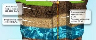
In vertical and horizontal versions (in the form of a rotated letter “G” - like this “I___”. Such an electrode is placed in the ground: vertical version - in a pre-made well of the required depth (2.5 - 3.5 meters); horizontal version - in a pre-dug ditch 0.7 meters deep and 2.5 meters long. Moisture from the soil is absorbed by the salts in the electrode and comes out in the form of a solution (electrolyte) into the same soil, saturating it and causing a decrease in its electrical resistivity. Because of this, it decreases grounding resistance of the electrode (pipe) placed in this soil.
Because the mixture of salts is in granules and contains a special additive; it does not dissolve in its entirety in the spring, when the soil is saturated with water. In this way, a long-term and uniform release of electrolyte from the electrode is achieved, gradually increasing (and not just maintaining) the concentration of ions in the surrounding soil. Typically, the factory “filling” of the electrode lasts for 15 years, after which repeated “refueling” is possible.
The use of stainless steel pipes as a material and the use of a less aggressive salt mixture than NaCl ensure the service life of the “shell” of such an electrode for at least 50 years.
D2.1. Features of the solution
D2.1.1. Easy to use in permafrost or rocky soils
The design of the electrolytic grounding electrode allows it to be used in “problematic” soils.
Permafrost soils are constantly (all year round for hundreds of years) in a frozen state.
Found in the North of our country. The freezing depth of such soil reaches 2 kilometers (in the Yakutsk region). Permafrost begins from 1-2 meters from ground level, i.e. from a depth that the sun cannot warm in the summer. Permafrost soil is very difficult for the construction of ground electrodes: it has a very high electrical resistance (100-300 times higher than loam) and has the ability to “push out” metal electrodes due to the effect of water expansion when freezing. This occurs after summer thawing of the soil (transition of ground moisture into a liquid state) under these electrodes. Rocky soil, containing a large number of stones ranging in size from a fist to meter-long boulders, is no less difficult for the construction of ground electrodes in that it is difficult to immerse electrodes in it in the usual way - stones get in the way.
To install an electrode of this type in a horizontal version, you only need a shallow ditch (0.7 meters), which is relatively easy to dig in both types of soil.
Placing the electrode in the top layer of soil above the permafrost eliminates the “pushing” effect. The small depth of the electrode also makes it possible for its limited use in rock formations - if there is at least a meter-long layer of crumbly soil above the stone monolith (for “impregnation” with electrolyte).
D2.1.2. Compactness
An electrolytic ground electrode is up to 12 times more efficient than a conventional steel electrode of the same size. This means the required number of grounding elements is reduced by 12 times, which means the area occupied by them is significantly reduced. At the same time, the dependence of the grounding resistance on the season is greatly weakened due to a decrease in the freezing temperature of water when the salt concentration in it increases to -5 degrees (the temperature of ordinary soil under a snow cap). This eliminates the need to use additional ground electrodes to compensate for increased resistance in winter.
D2.1.3. Talik formation
The ability of the electrode to reduce the freezing temperature of the soil also has a negative aspect. A talik zone (wiki) is formed near the electrode, which can pose a danger to the foundation of a nearby building or road surface. The talik zone on the ground surface is an oval measuring about 3x6 meters. Therefore, during design work it is necessary to take this into account and distance the electrodes from objects that could be damaged.
D2.1.4. No welding
To connect the grounding conductor to the mounted electrode, a special bolt clamp made of brass or stainless steel is used.
D2.2. Calculation of the resulting grounding resistance
I will give an example of calculating the grounding resistance of a horizontal electrode, because This is the most common option in practice, having a length of the horizontal part of 2.4 meters
and its diameter of
65 mm
.
The soil, as usual, will be homogeneous loam with a specific electrical resistance of 100 Ohm*m
.
The grounding resistance of a single horizontal grounding electrode is calculated by the formula:
In the case of an electrolytic grounding electrode, a coefficient is added to the formula that describes the concentration of electrolyte in the soil near this electrode:
The coefficient varies from 0.5 to 0.05. It gradually decreases, because the electrolyte penetrates into the soil to a greater volume, thereby increasing its concentration. In normal soil it is 0.125 after 1-2 months of salt leaching. The process can be accelerated by adding water to the electrode at the final stage of installation.
R1 will be 4.14 Ohm (at C = 0.125, p = 100 Ohm*m, L = 2.4 m, d = 0.065 m (65 mm), T = 0.6 m (T is the distance from the upper ground level to the middle of the buried electrode)
).
An excellent result for a single ground electrode measuring only 2.4 meters! But, as always, the price to pay for the result is the price of such an electrode... Which is discussed below in paragraph E2.4. (flaws).
D2.3. Installation
Installing a horizontal electrolytic grounding electrode is the simplest of all the methods I have encountered. In essence, this is a banal burying of the electrode to a shallow depth. A ditch is dug 0.7 meters deep and 2.5 meters long. The electrode is lowered to the bottom. Using a bolt clamp, the grounding conductor is connected. The ditch is being dug in.
Additionally, you can pour 5 liters of water into the neck of the electrode to speed up the leaching process.
D2.4. Advantages and disadvantages
Advantages:
- simplicity and ease of installation
- very high efficiency of the ground electrode, providing low ground resistance
- compactness, allowing installation of the ground electrode in a small area. However, taking into account the negative feature described in paragraph D2.1.3.
- long service life of the grounding electrode (at least 50 years) when it is “topped up” with a mixture of salts. The solution was originally created with this property.
- very weak seasonal dependence of grounding quality
- no welding needed. The structural elements are reliably mated without it.
Flaws:
- high price of the electrode (40-60 thousand rubles per electrode), which limits its widespread use. It is recommended to use electrolytic grounding in permafrost or rocky soils, in which conventional construction methods do not achieve the required result or are even more expensive.
- the need to move away from the foundations of buildings and roads
That's all.
Thank you for your attention! Sorry for the large amount of information. Questions can be asked in the comments or directly at my contacts indicated in the profile. I am always happy to help to the best of my ability and knowledge to anyone interested. Don't be shy Remember: there are no stupid questions - there are stupid answers.
PS My knowledge in the field of protective devices and electrical networks is very meager and superficial. Please keep this in mind.
Alexey Rozhankov, technical specialist
The following materials were used in preparing this article:
- Publications on the website “Grounding and lightning protection on ZANDZ.ru”
- Rules for the Construction of Electrical Installations (PUE), part 1.7 as amended by the seventh edition (Google)
- Instructions for the installation of lightning protection of buildings and structures RD 34.21.122-87 (Google)
- Technical circular 11/2006 of the association "Roselectromontazh" (google)
- GOST R 50571.21-2000 (IEC 60364-5-548-96) Grounding devices and electrical potential equalization systems in electrical installations containing information processing equipment (Google)
- Underground corrosion (United States. National Bureau of Standards. Circular 579) Author: Melvin Romanoff; Publisher: US Govt. Print. Off., 1957)
- Own experience and knowledge
Restrictions on use
ZZ-6 is designed for installation in
soft clay soils (for example, loams). It is difficult, but acceptable, to install in dense clay soils (for example, heavy clay).
Installation in hard sandy and rocky soils is not possible. This limitation is due to the low impact energy of the hand tool (sledgehammer) used during installation.
To install a grounding switch in dense or hard soil, we recommend using modular grounding kits (on a separate page).
Risk of system explosion
Destruction of ventilation ducts can occur when accumulated static electricity is discharged in them. This phenomenon is associated with the rapid movement of air combined with vapors of organic solvents along a synthetic hose.
For this purpose, the spiral wire of the main unit must be connected to the ground wire. If the unit is equipped with an exhaust device, it is attached to the housing.
Grounding of all equipment and duct connections require regular inspection. React appropriately if the exhaust structure becomes dislodged and severe vibration occurs.
Packaging information
Article: ZZ-6
The kit is packaged in a strong cardboard box with a plastic carrying handle. Inside the box are parts of the grounding kit, as well as an installation manual and a pair of proprietary stickers for placement on the electrical panel door or other flat surface at the buyer's discretion.
| ZZ-6 | |
| Weight: | 12 kg |
| Length: | 155 cm |
| Width: | 25 cm |
| Height: | 7 cm |
Price - 12,000.00 RUR.
Buy Order installation
Deep grounding rods (grounding rods) - the basis of a modular design
Let us dwell in more detail on the basic element of ready-made grounding kits, namely grounding rods or, as they are also called, pins and grounding conductors.
There are three varieties of them on the Russian market: based on copper-plated (abbreviation in catalogs St/Cu), galvanized (St/tZn, St/FT) and stainless steel (V2A, NIRO).
We strongly recommend not to use cheap pins made of regular (black) steel, especially those with a diameter of 14-16 mm, which some suppliers offer as an option. They will rot much sooner.
Overseas manufacturers also offer all-copper rods and stainless steel rods containing molybdenum (V4A), but these are usually non-stock items and are very expensive.
Galvanized rods
To obtain a zinc layer, 2 methods are used:
Hot galvanizing. Steel rods are dipped in zinc melted to 450-460 degrees. During the process of diffusion, zinc atoms penetrate the outer surface of the steel, forming a surface iron-zinc alloy. Depending on the conditions of the method (immersion time, cooling process, quality of the base material, its chemical composition, etc.), the thickness of the layer and its color may vary.
Galvanic galvanizing. Produced in electrolytic baths.
Galvanic looks more aesthetically pleasing, since the coating lays down evenly, repeating the geometry of the product, but is significantly inferior to hot coating in terms of corrosion resistance, whose coating thickness is several times higher (the difference can reach tens of times), which significantly affects the service life. Cold galvanizing technology is cheap, so products cost less.
Copper-plated rods
Copper plating of steel is carried out only by galvanic method. In industrial production conditions, pins are placed in special baths with a copper solution, equipped with automation and control equipment. Copper has strong adhesion, so the process of electrochemical reactions proceeds faster and the manufacturing cycle is shorter.
ATTENTION! According to various estimates, the Russian market now contains up to 50% of low-quality products from China. Basically, these are just copper-plated sets that are of dubious origin, as are the brands of materials from which they are made
For example, the rods are based on low-grade steel, the declared diameters of the products may not coincide with the actual ones, and the copper plating technology is artisanal. As a result, the copper-plated layer is weak, the consumer receives a product with low mechanical and anti-corrosion properties.
Stainless steel rods
The most reliable steel grade for deep grounding. It should be noted that in Europe (in particular in the birthplace of lightning protection - Germany), where the standards are more stringent, it is allowed to use only stainless steel. Often, for our climatic conditions and soil specifics, they recommend using only it, and in the V4A version.
The most important thing is the length L and outer diameter D of the grounding electrodes. The higher they are, the better the current spreading rate (more charge spreads from a larger area). The most common lengths are 1.2 or 1.5 meters, and diameters are from 14 to 25 (the most popular are 14 or 16 mm; among Western companies, which place higher demands on components, it is from 20 to 25 mm).
An important characteristic of grounding conductors is the way they are connected to each other. At the connection point (end of the pin) there are structures:
- threaded
- with lead balls
- with a trunnion connection (knurled double, triple or stepped)
- combinations of trunnions and lead insert
The first method requires screwing on adapter couplings, the other two ensure contact between the electrodes due to self-adhesive elements: knurled pins or lead balls, which, when the ground electrodes are deepened using a hammer or vibrating hammer, spread and fill the cavity inside the electrode.
Dealers in Russia and CIS countries
You can purchase ready-made ZANDZ grounding kits, as well as individual components, not only in our online store, but also from a friendly trading company that has its own warehouse in the city where we operate.
Purchasing from a local dealer will save you time and money on delivery of goods from the central warehouse in Moscow. If the dealer has a sales floor, you can get acquainted with the grounding kits and components “live”.
List of dealers in Russia and the CIS
What else is included?
Let's look at the components of ready-made grounding kits available on the Russian market. A lot has been said about the rods above, so let’s talk about the rest of the components:
For better immersion into the ground, a starting tip is installed at the end of the first rod. In Russian kits it is made of black steel (St), in German kits it is made of refractory cast iron (TG/FT) or galvanized steel (St/FT).
In domestic kits for connecting rods, couplings (made of stainless steel or brass) are screwed onto their adjacent ends. The German ones exclude the use of this element, since they are connected into a joint according to the “male - female” principle (see above), due to which they do not have a thickening of the diameter of the structure at the junction and, as a result, a more reliable connection is obtained with good electrical contact between adjacent ground electrodes.
To transmit impact force during installation, our rods have an impact-receiving head (bolt) screwed into the coupling from the opposite side, while with German rods it is simply put on the end of the rod with a knurled pin. Visually, these are two different elements; domestic ones have an impact bolt made of black steel (St), while imported ones have an impact tip made of ductile cast iron (TG/FT).
To improve the quality of connection of elements and better current conductivity, the kits are supplied with conductive lubricant, the consistency of which varies from liquid to paste. It is applied at the junction points of structural components.
A diagonal or cross clamp (connector) is placed on the last (upper) electrode, and a grounding conductor (round rod or strip) is also connected to it. It is made of stainless or galvanized steel, the latter for better corrosion resistance is best used with PVC coating.
The junction of the rod and the grounding conductor through the clamp is bandaged with anti-corrosion tape.
Optionally, modular pin kits are supplied with a hammer drill attachment and a grounding conductor, sometimes also a grounding bus.
Grounding kit ZZ-6
(pr. Russia) contains all the necessary parts for installing the ground electrode, which are easily mated to each other.
Copper-plated coupling-free grounding pin (D17 mm / L1.5 m) 4 pieces
The basis of the kit is a 1.5 m long pin with a thick copper coating (for maximum service life). One of the ends is narrowed; a blind hole is made at the other end to connect the pins to each other (to increase the total length of the electrode).
During installation, the connection is automatically pressed, forming a very reliable electrical and mechanical contact.
To install couplingless pins, it is necessary to use a dowel that transmits the impact force to the center of the pin.
| ZZ-6-1 | |
| Pin diameter: | 17 mm |
| Length: | 1.51 m |
| Weight: | 2.75 kg |
| Thread diameter: | 16 mm |
Detailed information about production technology and coating testing is presented on a separate page.
Dowel for installation with a sledgehammer 1 piece
The hardened steel dowel is designed to transfer the impact energy of the tool (sledgehammer) to the center of the pin. During installation it is located in the groove part of the pin.
| ZZ-6-4 | |
| Weight: | 0.12 kg |
| Length: | 70 m |
| Diameter: | 16 mm |
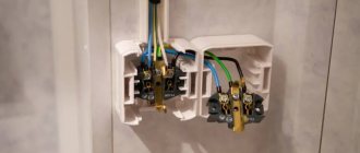
Clamp for connecting conductor 1 piece
Profiled stainless steel clamp with M10 bolts. Allows you to connect the rod to a grounding conductor - a round wire or strip (up to 40 mm wide).
It is possible to safely use steel and galvanized conductors - for this purpose, there is a gasket inside the clamp that prevents the formation of an electrochemical bond between steel/zinc and copper.
To prevent self-unscrewing of bolt-nut threaded connections, spring washers (Grover washers/Grover washers) are installed between the clamp surface and the nut.
| ZZ-6-5 | |
| Weight: | 0.358 kg |
| Length: | 80 mm |
| Width: | 80 mm |
| Height: | 30 mm |
Design features
Unlike the grounding loop, in the manufacture of which a metal profile (corner) is used as vertical and horizontal electrodes, in a modular-pin type system the structural elements are made of the following materials:
- vertical electrodes are made of copper-plated steel rods 1.5 meters long;
- horizontal electrodes - steel (copper) strip or copper wire;
- couplings - made of copper-plated steel, used to connect electrodes;
- connecting clamps - made of brass, used to connect vertical and horizontal electrodes, connection to grounded objects.
On the market for similar products, modular-pin grounding systems produced on an industrial scale are additionally equipped with the following components:
- tips made of steel;
- steel landing pad;
- special paste.
Tips are used to facilitate the installation of electrodes; a threaded connection is used for their fastening. The landing pad is fixed to the rod using a threaded connection and serves to transfer the forces of the vibrating hammer to the vertical electrode being driven.
A special paste is needed to treat the junctions of electrodes (couplings, tips) and the junctions of vertical and horizontal electrodes (couplings).
Treatment with paste allows you to protect the contact points from corrosion, thereby reducing the resistance to spreading in these areas of the grounding system.
Before installation
When placing a grounding electrode INSIDE a house, the installation location is determined based on considerations of the mechanical protection of the grounding conductor from this grounding electrode to the electrical panel at the place where it is installed, the dryness of the room, and the convenience of installing the pins in the ground. The best location would be a position within a radius of 0.5 meters from the shield to achieve the shortest conductor length. The maximum distance from the shield is not limited.
When placing a grounding conductor OUTSIDE the house, you need to take into account that the grounding conductor must be laid to a depth of 0.5 - 0.7 meters in a pre-dug channel. This measure is mandatory and necessary to protect the conductor from mechanical damage during operation and to minimize weather / seasonal influences, which increases its service life. The ground electrode is mounted in the same channel. The grounding conductor is inserted through the wall inside a steel pipe.
Necessary materials:
- kit “Grounding in a private house” ZZ-6
- copper wire/cable with a cross section of 16 or 25 mm² of the required length. When laying in the ground, a conductor with a minimum cross-section of 25 mm² is required.
- silicone sealant
Required tools:
- percussion hand tool weighing 300 - 1500 g: sledgehammer or heavy hammer
- two wrenches or two pliers (to tighten the clamp bolts)
Advantages and disadvantages of the system
The advantages of the modular pin system include:
- Ease of installation work.
- The use of long-length vertical electrodes allows the system to be mounted in a limited area of space while maintaining the required spreading current parameters.
- The work requires a minimum amount of labor, which determines the size of the installation team (1 - 2 people).
- There is no need to use welding equipment.
- The use of hand-held power tools (electric or pneumatic breaker) significantly reduces labor costs and work time.
- The use of copper-plated rods and connecting elements, in the manufacture of which corrosion-resistant metals are used, significantly increases the service life of the system.
- The system elements are manufactured on an industrial basis and sold as a set, which ensures the quality of the elements used and the possibility of quick installation.
The main disadvantage is the high cost due to the quality of materials and the presence of structural elements (tips, couplings, clamps), the manufacture of which requires special types of processing.
When installing a grounding system, all measurement results are documented in appropriate protocols, the measurements themselves must be carried out by an electrical measuring laboratory registered in the manner prescribed by law, and a grounding device passport is issued for the grounding loop.
The procedure for installing the ground electrode
Stainless steel sealing sleeves are mounted on pins for easy transportation. The bushings must be removed before installation.
Performed operations:
- Insert a dowel into the pin hole.
- Drive the pin into the ground, striking the pin with the tool.
- Remove the dowel and place the bushing on the mounted pin (with the wide part down).
- Insert the next pin with the pointed part into the mounted pin with the bushing on. The connection is self-pressed during installation.
- Repeat steps 1-4 until the ground electrode reaches the desired depth. The last pin must be left 20 cm above the ground. The sleeve does not fit onto the last recessed pin.
- Install the clamp for connecting the grounding conductor and, having connected the conductor itself, tighten the clamp bolts with maximum force.
- Fill the hole in the pin generously with sealant to prevent moisture from entering.
An example of grounding installation in a private house
See also a full description of the calculations and a video recording of the grounding installation on a separate page.
Operating principle and installation features
All elements included in the kit, after assembly, form an integral modular structure and represent a ready-made grounding loop.
A rod assembled from its component parts can be driven to a depth of 30-40 meters. The ends of each such pin are equipped with threads and through couplings they are combined into one unit to the required length. That is, the rod is gradually built up by the next element as it deepens.
The technology for installing vertical pins is as follows. A steel tip is screwed onto the lower part of the first rod, and a screw connection is made to the mounting coupling on top. This element is equipped with a special attachment that can withstand impacts from a rotary hammer or vibratory hammer.
The vertical position of the pin during driving is maintained thanks to a special clamp. After the first rod has entered the ground approximately 1.3-1.4 m, the mounting coupling must be removed and the next pin must be screwed in instead using the coupling coupling. The clamp continues to hold the structure vertically and gradually rises up relative to the driven rod. On top of the second pin, a mounting coupling with an attachment for a vibrating tool is again installed.
In the same way, all other grounding conductors are installed in the quantity provided for by the project. After that, they are connected to each other into a single whole using horizontal elements and brass clamps. Before installing the clamps, paste is applied to the joints, and upon completion of installation work, the circuit is completely coated with anti-corrosion protection. The service life of such grounding systems is about 30 years.
Requirements for the quality of grounding at home
If you do not plan to connect lightning protection and gas equipment to grounding:
- in ordinary clay soil, high-quality local (repeated) grounding should have a recommended resistance of no more than 30 Ohms (at a linear voltage of 220 V from a single-phase current source or at a linear voltage of 380 V from a three-phase current source)
- in sandy soil, high-quality local (repeated) grounding should have a recommended resistance of no more than 150 Ohms (with a linear voltage of 220 V of a single-phase current source or with a linear voltage of 380 V of a three-phase current source)
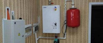
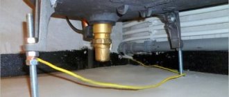
Why do you need to ground gas boilers?
Despite the fact that gas equipment is not an electrical appliance, static electricity collects on its surface during operation. It accumulates on the metal casing of the units and forms a strong electromagnetic field, which can damage the electronic “stuffing” of gas equipment.
The reason for this energy accumulation is that the units are attached to the wall or installed on the floor. These are non-conductive surfaces. The accumulation of static electricity reaches its maximum value during the winter heating period. You can get rid of it only with the help of grounding.
Requirements for grounding quality (special cases)
If grounding will be used together with lightning rods:
- in ordinary clay soil, the grounding resistance should be no more than 10 Ohms (RD 34.21.122-87, clause.
- in sandy soil, the grounding resistance should be no more than 40 Ohms (RD 34.21.122-87, clause 8; for soils with electrical resistivity more than 500 Ohm*m)
In this case, the ground electrode must contain at least 3 vertical electrodes, spaced apart from each other at a distance of at least two immersion depths of the electrodes (RD 34.21.122-87, clause 2.2.d).
Read more about this application on the separate page “Lightning protection and grounding”.
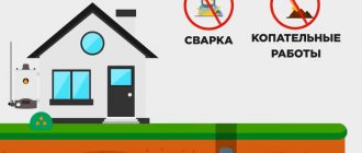
If grounding will be used to connect a gas boiler / gas pipeline:
- in ordinary clay soil its resistance should be no more than 10 Ohms (PUE 1.7.103; for all repeated groundings).
- in sandy soil its resistance should be no more than 50 Ohms (PUE 1.7.103; for all repeated groundings; for soils with a resistance of more than 500 Ohm*m).
It is recommended to make the grounding electrode in the form of one electrode (point grounding). Read more about this application on the separate page “Grounding a gas boiler / gas pipeline”.
Why is grounding needed?
When a short circuit occurs, the temperature of the conductor will rise sharply, causing melting of both the insulation and the conductive strands themselves. If you touch the wires at the moment of a short circuit, current will flow through the body, which can be fatal. This happens because the current always tends to follow the path of least resistance - that is, into the ground.
Grounding is a path that directs electricity directly to the ground, where it cannot harm anyone. The current always chooses the path with minimal resistance, and the ground loop has exactly this property. When a power leak occurs, the excess is immediately sent to the ground loop. Thus, even if a person receives an electric shock, it will not be severe, since most of the electrical energy will go through the grounding system.
It turns out that grounding is an important component of the electrical safety system. It must be said that grounding is a necessary part of any objects that use electricity. According to the requirements of regulatory documents, any building containing alternating current networks with voltages over 100 W must be equipped with a grounding system.
Grounding not only ensures safety, but also protects household appliances. The grounding loop takes on excess load during network fluctuations, reduces the impact of interference and neutralizes the negative effects of electromagnetic radiation.
Choosing a grounding system (TT / TN) for a private house
In 2007, the Department of State Energy Supervision sent a letter (No. 10-04/481) to the heads of MTU and the heads of UTEN Rostechnadzor, stating that in order to clarify and supplement the requirements of regulatory and technical documents in the electric power industry and ensure safety measures during the operation of electrical installations, ( approved / agreed upon) technical circulars (TC), which are recommended to be used for guidance and application when checking design documentation and commissioning new and reconstructed electrical installations:
- No. 6/2004 dated February 16, 2004 “On the implementation of the main potential equalization system at the entrance to buildings”;
- No. 7/2004 dated 04/02/2004 “On the installation of electrical wiring behind suspended ceilings and in partitions”;
- No. 10/2006 dated 02/01/2006 “On temporary power supply schemes for construction sites”;
- No. 11/2006 dated October 16, 2006 “On grounding electrodes and grounding conductors”;
In the commentary to TC No. 11/2006 “On grounding electrodes and grounding conductors” (from the developer of this TC: Mr. Shalygin A.A., head of the ICC of the Moscow Institute of Energy Safety and Energy Saving) it is stated:
In accordance with the instructions of clause 1.7.59 of the PUE of the seventh edition: “Power supply of electrical installations with voltage up to 1 kV from a source with a solidly grounded neutral and with grounding of open conductive parts using a ground electrode not connected to the neutral (TT system) is allowed only in those cases when electrical safety conditions in the TN system cannot be ensured. To protect against indirect contact in such electrical installations, the power must be automatically turned off with the mandatory use of an RCD...”
An example of an electrical installation where it is impossible, within the limits of reasonable technical solutions, to meet the electrical safety requirements in the TN system is individual residential buildings, which, according to local conditions, must be connected to a 0.4 kV overhead line made with bare wires (OHL). The fact is that the neutral conductor of an overhead line cannot be considered as a PEN conductor by definition. Under these conditions, before replacing bare overhead line wires with self-supporting insulated wires, the use of a TT protective grounding system is justified.
At the input to such installations, for automatic power off, an RCD with a rated differential operating current of 300 or 500 mA is usually installed. The resistance of the grounding device is chosen to be about 30 Ohms, and for soils with high volumetric resistance up to 300 Ohms. With such parameters of the grounding device, reliable operation of the RCD is ensured, and short-circuit currents are insignificant.
Later, in 2012, TC No. 31/2012 “On re-grounding and automatic power outage at the input of individual construction projects” was published. Its text (with some abbreviations):
Individual construction projects, as a rule, receive power via a branch from overhead power lines with voltages up to 1 kV.
For new construction projects and during reconstruction, in accordance with the instructions of Chapter 2.4 of the PUE of the seventh edition, overhead lines are made using self-supporting insulated wires and are designated as VLI.
Most existing individual construction projects receive power from overhead lines using uninsulated overhead line wires, made according to the standards of Chapter 2.4 of the PUE of the sixth and earlier editions.
... The purpose of this circular is to issue specific recommendations for ensuring protection against indirect contact in electrical installations receiving power from overhead lines and overhead lines up to 1 kV. When choosing measures to protect against indirect contact in electrical installations receiving power from overhead lines and overhead lines up to 1 kV, you must be guided by the following:
- Since for objects receiving power from overhead lines with voltages up to 1 kV, it is impossible for most consumers to meet the requirements for automatic shutdown due to low multiples of short-circuit currents, the installation of a residual current device (RCD) with a differential operating current of up to 300 mA at the input is mandatory . Note. The installation of an RCD with a differential operating current of up to 300 mA at the input is also mandatory from the point of view of ensuring fire safety.
- When powered from a VLI, the consumer's re-grounding resistance is selected from the condition of ensuring reliable operation of the RCD in the event of insulation damage (single-phase ground fault) when the PEN conductor of the branch from the VLI is disconnected. The resistance is calculated based on the reliable operation current of the RCD, equal to five times the size of this current, but should not exceed 30 Ohms. If the soil resistivity is more than 300 Ohm*m, the resistance can be increased to 150 Ohm.
- When powered from an overhead line, in accordance with the instructions of clause 1.7.59 of the seventh edition of the PUE and clause 531.2.3 of IEC 60364-5-53 (the Russian analogue of GOST R 50571-5-53 is being prepared for release), the TT protective grounding system should be used . The re-grounding parameters are selected in accordance with the instructions in paragraph 2 of this technical circular.
- The use of the TT system is considered as a temporary (forced) measure. After the reconstruction of overhead lines and the transition to overhead lines in electrical installations, you should switch to the TN protective grounding system; for this, a jumper should be installed in the input device between the N and PE buses.
Equipment
ZANDZ ready-made modular grounding kits are a universal solution for typical cases. If necessary, the kit can include any required number of components (individual kits are available upon request).
| ZZ-000-015 | ZZ-000-030 | |
| Copper-plated threaded grounding pin (D14; 1.5 m), pcs. | 10 | 20 |
| Threaded coupling, pcs. | 10 | 20 |
| Starting tip, pcs. | 3 | 3 |
| Guide head for attachment to a jackhammer, pcs. | 2 | 3 |
| Clamp for connecting conductor, pcs. | 3 | 3 |
| Conductive grease, pcs. | 1 | 1 |
| Waterproofing tape, pcs. | 1 | 1 |
| Jackhammer attachment (SDS max), pcs. | 1 | 1 |
| ZZ-000-045 | ZZ-000-424 | ZZ-000-636 | |
| Copper-plated threaded grounding pin (D14; 1.5 m), pcs. | 30 | 16 | 24 |
| Threaded coupling, pcs. | 16 | 16 | 24 |
| Starting tip, pcs. | 15 | 4 | 6 |
| Guide head for attachment to a jackhammer, pcs. | 5 | 3 | 3 |
| Clamp for connecting conductor, pcs. | 15 | 4 | 6 |
| Conductive grease, pcs. | 1 | 1 | 1 |
| Waterproofing tape, pcs. | 5 | 2 | 2 |
| Jackhammer attachment (SDS max), pcs. | 1 | 1 | 1 |
Additional items
ZANDZ inspection/control well for maintenance (for all types of soil; plastic)
A polypropylene well is necessary to provide access to the point of contact between the grounding electrode (grounding pin) and the grounding conductor. Installed above the connection point at the same level with the ground.
| ZZ-550-002 | |
| Weight of 1 meter: | 2.6 kg |
| Length: | 290 mm |
| Width: | 240 mm |
| Height: | 205 mm |
Copper-plated steel wire (D 10 mm / S 80 mm²)
Steel wire with a high-quality copper coating 70 microns thick is used as a grounding conductor with a long service life (30 years or more).
The conductor is supplied in coils of 10/20/50 meters (GL-11150-10 / GL-11150-20 / GL-11150-50).
| GL-11150 | |
| Weight of 1 meter: | 0.63 kg |
| Diameter: | 10 mm |
Grounding conductor (PV-1 25 mm²)
Single-core, stranded and stranded copper conductor with a cross-section from 4 to 185 mm² in PVC insulation is used to connect the ground electrode to the object (GZSh in the shield).
The conductor is supplied by the meter and in ready-made coils of 3/5/10 meters (ZZ-500-103 / ZZ-500-105 / ZZ-500-110), crimped at one end with a tip with a hole for a D8 bolt for connection to the main shield in the shield .
| Bays | ZZ-500-103 | ZZ-500-105 | ZZ-500-110 |
| Length: | 3m | 5 m | 10 m |
| Weight: | 1.4 kg | 2.3 kg | 4.55 kg |
| Outer Diameter: (with insulation) | 7.5 mm | 7.5 mm | 7.5 mm |
| Bolt hole diameter: | 8 mm | 8 mm | 8 mm |
Straightening device
The straightening device is designed to straighten wires with a diameter of 6 to 10 mm and ground strips with a width of 20 to 45 mm and a thickness of 3 to 4 mm.
| ZZ-510-700 | ZZ-510-900 | |
| Weight: | 14.5 kg | 12 kg |
| Length: | 0.3 m | 0.6 m |
| Width: | 0.3 mm | 0.2 mm |
| Height: | 0.15 mm | 0.2 mm |
| Number of rollers | 7 pcs | 9 pcs |
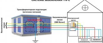
Recommended actions when replacing TN-C
Most residential buildings are equipped with this option. Due to the fact that the buildings have a two-wire electrical supply system, the use of TN-C is a suitable solution. Because the system uses only one conductor, which is capable of solving two problems:
- working, for the proper functioning of electrical products and devices;
- protective, which ensures the safety of devices.
Such a system meets basic safety standards and protects the entire electrical circuit, but it is not able to preserve the powered electrical units, which can lead to their failure when a high load occurs. It is also important to understand that in rainy weather, such a connection will lead to voltage surges, even if a protective shutdown is applied. Unfortunately, there are even cases of death due to this flaw.
Therefore, when constructing new buildings, using such a solution is highly not recommended. I use such a system only where it was originally installed, but if a person wants to change it, this can be easily done. Most often, people use TN-CS for these purposes, so a PEN cable is installed at the input, which is later divided into PE and N. Thanks to this solution, in the event of an emergency, the N wire is disconnected from the general network, which allows you to keep all household appliances intact and will save a person from additional costs.
What is popular now and the main recommendations
Today, three grounding options are more common, each of which differs in technical parameters and capabilities:
- TN;
- TT;
- IT.
If a person plans to use the set only in a country house, then it is better for him to pay attention to the first option, which is also divided into several groups and can be: TN-C, TN-S, TN-CS, what you choose is decided based on your goals.