Protective grounding is the deliberate connection to the ground of metal parts of an electrical installation that are not energized (disconnector drive handles, transformer casings, support insulator flanges, instrument transformer housings, etc.).
Installation of grounding devices consists of the following operations: installing grounding conductors, laying grounding conductors, connecting grounding conductors to each other, connecting grounding conductors to grounding conductors and electrical equipment.
Vertical grounding rods made from angle steel and rejected pipes are immersed in the ground by driving or pressing, and from round steel - by screwing or pressing. This work is carried out using mechanisms and devices, for example: a copra (driving into the ground), a device for a drill (screwing rod electrodes into the ground), a PZD-12 mechanism (screwing grounding electrodes into the ground).
For grounding devices, the most common are electric deepeners that have a standard electric drill and a gearbox that reduces the rotation speed below 100 rpm and accordingly increases the torque on the screwed-in electrode. When using these deepeners, a spigot tip is welded to the end of the electrode, which loosens the soil and facilitates immersion of the electrode. The commercially produced tip is a steel strip 16 mm wide, pointed at the end and bent along a helix. In installation practice, other types of electrode tips are also used.
When installing grounding, vertical grounding conductors should be laid to a depth of 0.5 - 0.6 m from the level of the ground level and protrude from the bottom of the trench by 0.1 - 0.2 m. The distance between the electrodes is 2.5 - 3 m. Horizontal grounding conductors and connecting strips between vertical grounding conductors are laid in trenches 0.6 - 0.7 m deep from the level of the ground level.
All connections in the grounding circuits are made by lap welding; Welding areas are covered with bitumen to prevent corrosion. The trench is usually dug 0.5 m wide and 0.7 m deep. The construction of the external grounding loop and the laying of the internal grounding network are carried out according to the working drawings of the electrical installation project.
Grounding conductors are introduced into the building in at least two places. After installing the grounding devices, an act for hidden work is drawn up, indicating on the drawings the connection of grounding devices to stationary landmarks.
Grounding main conductors are laid along the walls at a distance of 0.5-0.10 m from the surfaces at a height of 0.4-0.6 m from the floor level. The distance between the fastening points is 0.6 -1.0 m. In dry rooms and in the absence of a chemically active environment, it is permissible to lay grounding conductors close to the wall.
Grounding strips are secured to the walls with dowels, which are fired with a construction gun either directly to the wall or through intermediate parts. Embedded parts to which grounding strips are welded are also widely used. Using a PTs-type gun, you can shoot parts made of sheet or strip steel up to 6 mm thick into foundations made of concrete (grade up to 400), brick, etc.
In damp, especially damp rooms and in rooms with caustic fumes (aggressive environment), grounding conductors are welded to supports secured with dowels-nails. To create a gap between the grounding conductor and the base in such rooms, a stamped holder made of strip steel with a width of 25 - 30 and a thickness of 4 mm is used, as well as a bracket for laying round grounding conductors with a diameter of 12 - 19 mm. The overlap length during welding should be equal to twice the strip width for rectangular strips or six diameters for round steel.
Grounding conductors are connected to the pipelines; if there are valves or bolted flange connections on the pipes, bypass jumpers are made.
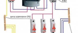
Parts of electrical installations to be grounded are connected to grounding lines with separate branches. Steel grounding conductors are connected to metal structures by welding, and to equipment - possibly by welding. grounding bolt or where the conductors are connected to copper conductors with fastening by wire banding and soldering. A common grounding loop is usually made around the substation, to which the grounding conductors of the interior of the substation are welded. Individual elements of electrical equipment are connected to grounding conductors in parallel, and not in series, otherwise, if the grounding conductor breaks, part of the equipment may become ungrounded.
At substations, all elements of electrical equipment and metal structures are grounded. Power transformers are grounded with a flexible jumper made of steel cable. The jumper is welded to the grounding conductor on one side, and connected to the transformer using a bolted connection on the other. The disconnectors are grounded through the frame, drive plate and support bearing; auxiliary contact housing - by connecting to the grounding bus.
Circuit location
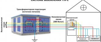
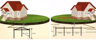
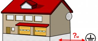
As a rule, grounding conductors are made of a metal strip or rod. The system includes external and internal circuits. Outside the building, the grounding strip is attached to electrodes buried in the ground at a distance of at least 1 m from the foundation and forming a grounding loop. Most often the contour has a triangular shape, but it can be laid in a line or around the perimeter of the building.
The installation depth is determined by the degree of soil freezing and is at least 0.5-0.7 m. A shallower depth is possible at the entrance to the building, where conductor entries are usually enclosed in metal pipes. It is recommended to lay horizontal grounding strips edge-on at the bottom of the trench. Their length is determined by the size of the contour and the distance to the building.
The external circuit is subject to atmospheric and underground corrosion. Destruction of the surface of conductors and fittings gradually reduces the effectiveness of protection. Painting underground parts of the grounding system is not recommended.
They are made from stainless steel and protective copper and zinc coatings. Inside the premises, a metal strip is laid openly along the building structures. In case of high humidity, a bracket for fastening the grounding strip is used.
Rolled steel
The grounding bus must have high electrical conductivity, ductility and good weldability. A steel strip is predominantly used as a flat conductor in systems for grounding and potential equalization. This universal type of rolled metal has a rectangular cross-section without internal voids and a flat shape. The strip is manufactured in accordance with GOST 103-2006 “High-rolled hot-rolled steel strip” and has a number of valuable qualities:
low cost;- long period of use;
- high strength.
This standard specifies general-purpose rolled steel with a thickness of 4 to 80 mm and a width of 10 to 200 mm. Depending on the purpose, strips of measured, multiple and unmeasured lengths are made. The specifics of steel rolling determine the requirements for the length of the rolled product. Strips made from ordinary steels are supplied in lengths of up to 12 m, from alloyed ones – up to 6 m. The minimum length is also regulated; for all types it is 2 m. Rolled steel has the advantage that the number of welded joints when used in a circuit is reduced.
The strip can be of normal or increased precision rolled. But this parameter, like the accuracy of angles or crescent shape, has virtually no effect on the quality of grounding and is not significant when choosing.
Galvanized
To extend the service life and protect from environmental influences, a zinc coating is applied to the steel in accordance with GOST 9.307-89 “Hot zinc coatings”. The steel strip is pre-treated and immersed in a container with molten zinc. The coating thickness is 40-200 microns. The thicker the layer, the more it contributes to increasing the strength of the product. The coating is strengthened by repeated immersion of the strip in molten zinc.
Galvanization is currently the most effective and cheapest method of protection. Coating increases the cost of rental, but its service life increases. The properties of zinc are preserved even with minor surface damage. The galvanized strip is resistant to corrosion, elastic, does not crack and has a neat appearance. It is produced from carbon and low-alloy steel grades by slitting steel sheets and is supplied in the form of coils weighing 50-60 kg or rods 5-6 m long.
According to the PUE, the minimum cross-section of the grounding conductor for installations with voltages less than 1 kV is 75 mm2. 4x20 mm strip is the most economical solution that meets these requirements. More often, a galvanized strip with a cross section of 4x40 mm, 5x40 mm, 5x50 mm is used to make a grounding loop. These products ensure compliance with standards and are convenient for grounding installation. According to the standard, one meter of 4x40 mm strip weighs about 1.3 kg. The weight of a linear meter is also regulated by GOST 103-2006 and is used to calculate the required amount of tape.
Attaching the ground strip to the wall
Fastening and connection of steel strip made of hot-dip galvanized steel with dimensions: 20x3, 20x4, 25x3, 25x4, 30x3, 30x4, 40x4, 40x5, 45x4, 45x5 mm - on conductor holders DP-45GC , (Album of technical solutions A18-01 “Fixing units for galvanized steel strips with a width of 20 to 40 mm, a thickness of 3 to 7 mm for walls, plinths, ceilings, parapets of buildings and structures" in PDF , in DWG )
Fastening and connecting steel strips made of hot-dip galvanized steel with dimensions: 40x4, 40x5, 50x4, 50x5 mm - on conductor holders DP-50GC ( Album of technical solutions A18-02 “Fasting units for galvanized steel strips with a width of 40 to 50 mm, a thickness of 3 to 7 mm to walls, plinths, ceilings, parapets of buildings and structures" in PDF, in DWG)
Fastening and connection of a steel strip made of hot-dip galvanized steel with dimensions: 50x4, 50x5, 50x6, 60x4, 60x5, 60x6 mm mm - on conductor holders DP-60GC , (See fastening units, Album of technical solutions A18-03 “Fixing units of galvanized steel strip width from 50 to 60 mm, thickness from 3 to 7 mm to walls, plinths, ceilings, parapets of buildings and structures" in PDF, in DWG )
Fastening and connection of a steel strip made of hot-dip galvanized steel 20x3, 20x4, 25x3, 25x4, 30x3, 30x4, 40x4, 40x5, 45x4, 45x5 mm and a circle 8-10 mm - on conductor holders DPU-30GC, DPU-4GC (See fastening units DPU-30GC and DPU-4GC)
These conductor holders are designed for installation both outdoors and indoors. A zinc coating with an average thickness of 55 microns using the hot-dip galvanizing method in accordance with GOST 9.307-89 reliably protects products from corrosion, and fasteners are made of A2 or A4 stainless steel (corresponding to AISI 304 or AISI 316 steel grades, respectively, A4 steel grade is installed at the Customer’s request) in accordance GOST ISO 3506-1—2014;
To install the products (see fastening points), it is necessary to mark the wall in 1-meter increments and drill holes with a diameter of 12 mm and a depth of 45 mm, blow them with compressed air, install a drive-in anchor (designation - DP-45ГЦ-01) and secure the support bracket of the conductor holder, then install the bottom plate, strip, top plate and tighten the bolts).
See also: attaching a grounding strip to a sandwich panel
See the catalog for products for connecting grounding strips 20x3, 20x4, 25x3, 25x4, 30x3, 30x4, 40x4, 40x5, 50x4, 50x5, 50x6, 50x7 mm with ZS clamps
Select the required grounding strip from the catalog
Developer, copyright holder and (ELMAST®), 603104, Russia, Nizhny Novgorod, Nartova St., 6
Copper
Along with galvanized strips, grounding strips with copper coating are widely used in practice. Copper is less electrochemically active than steel and zinc. Therefore, it lasts longer and can be used in more difficult conditions.
Copper-bonded grounding conductors have good ductility. They are supplied in unmeasured lengths, which is convenient for laying grounding loops. Copper strip is also used for the internal circuit as a main conductor used to connect equipment to it. The disadvantage of copper-plated grounding strips is their high price.
Inner circuit routing
Electrical equipment that must be grounded is located throughout the entire area of the production premises. It is connected to the grounding system by laying busbars inside the building. The installation of grounding conductors is done openly; there should always be free access to them for control and inspection. The exception is metal pipes for hidden electrical wiring and explosive installations, where openings are sealed with easily knocked out non-combustible materials.
The grounding strips of the internal circuit should be laid horizontally or vertically. Only if the building includes inclined structures, it is allowed to lay conductors parallel to them. The internal grounding loop is mounted using walls and ceilings; if it is necessary to lay it on the floor, the grounding strip is laid in channels. Rectangular conductors are mounted with a wide plane to the wall. The strip is fastened to brick and concrete surfaces by driving nails using a construction gun. Screws are used for fixing to wooden walls.
The grounding conductors are connected to each other by welding. With strong heating, the protective zinc coating evaporates, thereby reducing the resistance of the steel to external influences. Therefore, the connection points are treated with zinc spray or enamel. In places where the resistance of the grounding device is to be measured, the conductor is bolted. It should be removable, but only with a tool. The attachment points of the grounding strips should be at a distance of 650 mm to 1000 mm from each other. The larger the cross-section of the strip, the more frequently they are located.
The structure of a building may include expansion joints that protect it from deformation. The grounding strip crossing such a joint must have a compensating bend. Through walls and ceilings, the grounding strip is freely passed through openings or enclosed in a steel pipe.
Choosing a location for installing a gas shield
On an overhead line pole
If there is an additional input device in the section where the supply line is connected to the main ASU located at the serviced facility (on a pole, for example), then the GZSh can be mounted directly on it.
The requirements of current regulations (the same PUE, for example) require connecting a grounding bus mounted on a pole to the main distribution strip located in the internal input device.
Also, one should not forget about organizing the re-grounding of the PEN conductor on the pole by separating a separate PE grounding bus from it. The latter means that the specified structural element must be electrically connected to another grounding circuit, installed directly under the support.
In the ASU cabinet
The cabinet with the main busbar mounted in it can be placed directly on the facade of the house in a place previously provided for this. At industrial facilities and in buildings of various organizations, the installation of ASU, as a rule, involves the use of a special panel room for these purposes.
If the switchgear is located outdoors, the cabinet body must have an IP index corresponding to its operating conditions.
Installation of structural elements that implement a functional (working) grounding bus involves a whole set of special operations, during which the following points must be taken into account:
- for ease of installation, the main busbar is bolted to the steel cabinet body;
- during installation, the grounding bus must be connected to the “zero” rail using a steel (copper) jumper;
- its dimensions should be comparable to the cross-section of the protective and neutral working conductors;
- their placement relative to each other is not stipulated in any way by current regulations.
The cross-section of the PE grounding plate must be at least 10 mm2 (if it is made of copper). For a steel conductor this value cannot be less than 75 mm2.
Installation outside the cabinet
Outside the cabinet, the main grounding bar must be installed in places protected from unauthorized access and interference.
It is fixed within the boundaries of a hard flat surface on insulators made of a sufficiently strong material. As an example of open placement of a gas shield, let’s consider the installation of a standard 19-inch plate of the “TLK” brand.
The TLK-ERH-CU grounding bars, widely used in electrical engineering, are a certified product from TLK that meets all previously agreed upon requirements. During their manufacture, 14 to 18 mounting bolts are placed on a copper rail with a standard size of 19 inches (19”) for connecting the supply conductors.
According to the requirements for structures of this class, such a 19-inch rail with 14 (18) connectors should be installed in special cabinets manufactured by the same trading company. And only after this the finished structure is connected to the grounding system using a copper wire of the appropriate section.
Additional Information. The cabinet used to accommodate the 19-inch rail is appropriately designated “No. 19.”
Another option for arranging a grounding bus is to use special DIN rails for these purposes, which fall into the category of standard electrical products combined in one cabinet.
According to current standards (GOST, in particular), a set of such DIN rails can be intended for other purposes (they can be used as strips for connecting phase and neutral conductors).
Mounting on brackets
Fastening directly to walls is only permitted in rooms with a dry, non-aggressive atmosphere. If there is a large amount of moisture and caustic vapors in the air, grounding conductors should be welded to the supports. The distance to the wall must be at least 10 cm. Grounding busbar holders are made of steel, they are secured with pistol dowels or welded to bookmarks embedded in the wall. On complex surfaces, dowels with an expansion nut or nylon expansion dowels are used. The distance between supports should be from 600 mm to 1000 mm in a straight line, at corners of 100 mm from the turning point. The recommended height at which the bracket should be placed is 400-600 mm from the floor level.
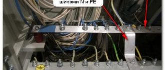
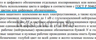
Grounding conductors are painted along their entire length with yellow and green stripes adjacent to each other. The color stripes must have the same width; for tires it is set in the range of 15-100 mm.
Grounding plays an important role in protecting people and property from damage. Thanks to it, sudden events such as lightning or a short circuit will not lead to casualties or damage to material assets.
The use of a steel strip as a grounding conductor has proven itself in practice and is considered effective and profitable.
How to properly install grounding bar holders
Flat grounding conductors are laid over a concrete or brick surface - for this they use a construction gun. And in stable, dry conditions, grounding buses can be laid directly along the foundations (walls). But in rooms where humidity is high or may periodically increase, as well as in the immediate vicinity of chemically active materials, grounding conductors must be laid on special holders for round and flat conductors (grounding bus holders).
These mounting devices must be installed in accordance with certain standards, such as:
- on turns, the distance should be 100 mm from the tops of the corners;
- the distance from the branch points should also be 100 mm;
- from removable channel ceilings (their lower surface) - 50 mm;
- from the floor - 400-600 mm.
Grounding bus holders are attached to special products mounted into the base (wall) by welding. In this case, the holder is fixed around the perimeter of the shank, as well as using dowels. The holders are attached to most substrates, such as concrete or brick, using pistol dowels. Sometimes other types of dowels are used: nylon spacer ones or with a spacer nut.
K-188 holders allow you to attach round (10-12 mm in diameter) and flat (40x4 and 25x3 mm) grounding elements to building structures. These holders are secured with a screw, welding or dowels. Round and flat grounding conductors are placed in the grooves provided for this purpose in the holder: in the upper (prism-shaped) and lower (rectangular), respectively. The conductors are fixed by bending the elements.
The acceptable load on the K-188 holders is 40 N.
The product is intended for long-term use in areas with a temperate climate under a special canopy or in well-ventilated areas (location category U2).
Installation of grounding conductors using K-188 holders should be as follows:
1) detailed markings; 2) drilling a hole to pass the conductor through the ceiling; 3) installation of grounding busbar holders on the surface; 4) laying main conductors for protection; 5) connection of conductors by welding; 6) treatment of joints with oil paint or other coating: zinc spray, nitro enamel.
It is customary to paint grounding conductors in yellow-green stripes 15-100 mm wide.