1.7.109
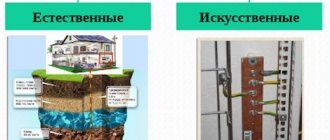
The following can be used as natural ground electrodes:
1) metal and reinforced concrete structures of buildings and structures in contact with the ground, including reinforced concrete foundations of buildings and structures that have protective waterproofing coatings in non-aggressive, slightly aggressive and moderately aggressive environments;
2) metal water pipes laid in the ground;
3) casing pipes of boreholes;
4) metal sheet piles of hydraulic structures, water conduits, embedded parts of valves, etc.;
5) rail tracks of main non-electrified roads and railways and access roads in the presence of a deliberate arrangement of jumpers between the rails;
6) other metal structures of structures located in the ground;
7) metal shells of armored cables laid in the ground. Cable sheaths can serve as the only grounding conductors when there are at least two cables. Aluminum cable sheaths are not allowed to be used as grounding conductors.
2.5.131
When passing overhead lines of 110 kV and higher in areas with clayey, loamy, sandy loam and similar soils with a resistivity of 1000 Ohm m, reinforcement of reinforced concrete foundations, supports and stepsons should be used as natural grounding conductors without additional installation or in combination with laying artificial grounding conductors. In soils with higher resistivity, the natural conductivity of reinforced concrete foundations should not be taken into account, and the required resistance value of the grounding device should be ensured only by the use of artificial ground electrodes.
The required resistance of grounding devices of 35 kV overhead line supports must be ensured by the use of artificial grounding conductors, and the natural conductivity of foundations, underground parts of supports and stepsons (attachments) should not be taken into account in calculations.
Main types
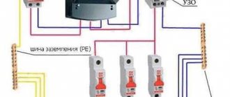
According to the PUE (Electrical Installation Rules), there is a TN grounding system (including groups TN-C, TN-S, TN-CS), TT and IT. The Latin letters in the designation have the following meaning:
- T – power source connected to ground;
- S – opening is carried out by different conductors;
- N – neutral;
- C – open with one conductor;
- I – insulated current-carrying part.
Knowing what each letter of the designation means, you can determine the structure and operating principle of the grounding device to which the electrical equipment is connected.
TN system
The most common protective grounding system. Its main feature is the presence of a “tightly” grounded neutral of the supply network. In other words, the zero output of the supply network is directly connected to the ground loop.
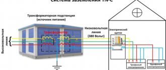
TN-C - this grounding system was widely used in the construction of old residential buildings, but nowadays it is not used in the construction of houses, as it is outdated and does not meet all safety standards. This type of grounding of electrical appliances is used in three-phase networks with a four-core cable and single-phase networks with cables having two cores. The main disadvantage of this type is the absence of a protective grounding conductor in the cables.
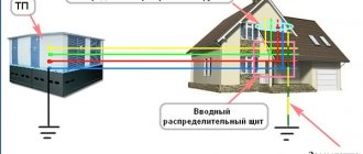
TN-S is a system often used to connect buildings to the electrical network. Has the highest degree of protection among all grounding systems. The neutral and working conductors, in this system, are laid separately from each other, while the protective conductor is connected to all current-carrying parts of the equipment being stripped. The disadvantages of this type of grounding include the need to lay an additional cable.
TN-CS - in this system, the protective conductor core is connected to the neutral working core. According to electrical safety regulations, the TN-CS system requires the installation of additional grounding.
TT system
This system is widely used to ensure electrical safety of supply substations and installations that have a separate grounding device. Often used to protect separate premises (garages, stalls, hangars and other structures).
IT system
The power source in this system is isolated by an air gap or connected by an element with high resistance, which can significantly reduce the leakage current. The IT type grounding system is most often used in medical institutions and laboratories to ensure the correct operation of high-precision, surge-sensitive devices.
2.5.129
The following must be grounded on the overhead line:
1) supports with lightning protection cable or other lightning protection devices;
2) reinforced concrete and metal supports of 3-35 kV overhead lines;
3) supports on which power or instrument transformers, disconnectors, fuses and other devices are installed;
4) metal and reinforced concrete supports of 110-500 kV overhead lines without cables and other lightning protection devices, if this is necessary under the conditions for ensuring the operation of relay protection and automation.
Wooden poles and wooden poles with metal traverses of overhead lines without lightning protection cables or other lightning protection devices are not grounded.
The resistance of the grounding devices of the supports given in clause 1, with their height up to 50 m, should be no more than those given in Table 2.5.19; with a support height of more than 50 m - 2 times lower compared to those given in Table 2.5.19. On double-circuit and multi-circuit overhead line supports, regardless of the line voltage and height of the supports, it is recommended to reduce the resistance of grounding devices by 2 times compared to those given in Table 2.5.19.
Table 2.5.19 The highest resistance of grounding devices of overhead line supports
| Specific equivalent soil resistance, Ohm m | Maximum resistance of the grounding device, Ohm |
| Up to 100 | 10 |
| More than 100 to 500 | 15 |
| More than 500 to 1000 | 20 |
| More than 1000 to 5000 | 30 |
| More than 5000 | 6·10 |
It is allowed to exceed the grounding resistance of some supports compared to the standardized values if there are supports with reduced values of grounding resistance, and the expected number of lightning outages does not exceed the values obtained when the requirements of Table 2.5.19 are met for all overhead line supports.
For mountain overhead line supports located at altitudes of more than 700 m above sea level, the grounding resistance values indicated in Table 2.5.19 can be increased by 2 times. The resistance of the grounding devices of the supports specified in paragraph 2 for 3-20 kV overhead lines passing in populated areas, as well as all 35 kV overhead lines should be no more than those given in Table 2.5.19: for 3-20 kV overhead lines in uninhabited areas in in soils with resistivity up to 100 Ohm m - no more than 30 Ohm, and in soils with resistivity above 100 Ohm m - no more than 0.3 Ohm.
The resistance of the grounding devices of the supports of overhead lines of 110 kV and higher, specified in clause 3, should be no more than those given in Table 2.5.19, and for overhead lines of 3-35 kV should not exceed 30 Ohms.
The resistances of the grounding devices of the supports specified in clause 4 are determined when designing the overhead line.
For overhead lines protected by cables, the resistance of grounding devices made according to lightning protection conditions must be ensured when the cable is disconnected, and under other conditions - when the cable is not disconnected.
The resistance of grounding devices of overhead line supports must be provided and measured at industrial frequency currents during the period of their highest values in the summer. It is allowed to take measurements in other periods with the results adjusted by introducing a seasonal coefficient, however, measurements should not be made during a period when the value of the resistance of grounding devices is significantly affected by soil freezing.
The place where the grounding device is connected to the reinforced concrete support must be accessible for measurements.
Carrying out the calculation of the protective circuit
To perform an accurate calculation of the ground loop, you must consider:
- soil moisture;
- average temperature in winter and summer in the installation area;
- soil resistance and salinity level;
- cross-section and length of grounding conductors and electrodes;
- distance from the house to the contour.
The calculation is made using formulas; this procedure is difficult for a person who does not have an engineering education. However, even if the correct calculations are made, the actual circuit resistance will differ from the calculated one due to the large number of influencing dynamic factors.
In fact, many take into account only the distance of the circuit from the foundation, and then adjust the resistance by measuring this indicator of the already installed structure.
- stripes – width – 40-50 mm, thickness – 4-5 mm, at least 2.5 m long;
- corners - shelf thickness - 4-5 mm, shelf width 40-50 mm, at least 2.5 m long;
- rods (necessarily smooth) – cross-section 16-20 mm, at least 2.5 m long;
- pipe – wall thickness 3.5 mm, diameter no less than 32 mm, length no less than 2.5 m.
Accurate calculations taking into account all parameters must be carried out if large commercial and industrial buildings need to be grounded.
GENERAL REQUIREMENTS
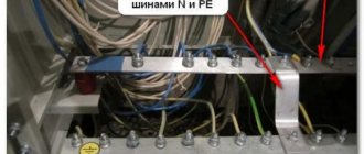
A combined neutral protective and neutral working conductor (PEN) in electrical installations up to 1 kV is a conductor that combines the functions of a neutral protective and neutral working conductor.
Expert opinion
It-Technology, Electrical power and electronics specialist
Ask questions to the “Specialist for modernization of energy generation systems”
Video “Making a contour and marking. Part 1” Voltage relative to ground during a short circuit to a housing is the voltage between this housing and the zero potential zone. Ask, I'm in touch!
Classification of grounding systems
The following grounding systems are distinguished:
- TN system (which in turn is divided into subtypes TN-C, TN-S, TN-CS)
- TT system
- IT system
The letters in the names of the systems are taken from the Latin alphabet and are deciphered as follows: T – (from terre) earth N – (from neuter) neutral C – (from combine) combine S – (from separate) divide I – (from isole) isolated According to the letters in the names grounding systems, you can learn how the power source is designed and grounded, as well as the principle of grounding the consumer.
TN system
This is the most famous and popular grounding system. Its main difference is the presence of a “solidly grounded” neutral of the power source. Those. The neutral wire of the supply substation is directly connected to the ground. TN-C is a subtype of the grounding system, which is characterized by a combined grounding and neutral neutral conductor. Those. they go in one wire from the supply transformer to the consumer. The absence of a separate PE (protective neutral) conductor in this system is clearly a disadvantage. The TN-C system was widely used in Soviet buildings and is unsuitable for modern new buildings because it lacks the ability to equalize potentials in the bathroom. TN-S is a system in which the protective conductor of the potential equalization system and the working neutral conductors run in separate wires from the power source to the electrical installation. This system is only becoming widely used when connecting buildings to power supply. Is the safest. The disadvantages include its high cost, because... installation of an additional conductor is required. TN-CS is a system in which the neutral protective conductor and the neutral working conductor are connected by a combined wire, and are separated at the entrance to the distribution board. According to the requirements of the Electrical Installation Rules, this system requires additional grounding.
TT system
This is a system in which the supply substation and the consumer's electrical installation have different grounding conductors independent of each other. The scope of application of the TT system is mobile objects with electrical installations of consumers. These include mobile containers, stalls, trailers, etc. In most cases, modular-pin grounding is used for the consumer in the TT system.
IT system
A system in which the power supply is separated from the ground through an air space or connected through a large resistance, i.e. isolated. The neutral in this system is connected to ground through a large resistance. The IT system is used in laboratories and medical institutions where high-precision and sensitive equipment operates.
Distance from ground electrode to...?
06.07.15
One of the most popular questions when organizing grounding is the question of the distance to objects that must be observed when installing a ground electrode. Let's look at this issue using the following regulatory documents:
- Rules for the construction of electrical installations (PUE);
- Instructions for organizing protective grounding and potential equalization in electrical installations (I 1.03-08);
- Guidelines for protecting secondary circuits of power plants and substations from impulse noise (RD 34.20.116-93).
1. Distance from the ground electrode to the foundation of the building
The answer to this question can be found in paragraph 1.7.94 of the PUE, which reads:
“...laying in the ground at a depth of 1 m and at a distance of 1 m from the foundation of the building or from the perimeter of the territory occupied by the equipment, a grounding conductor connected to the potential equalization system of this building or this territory, and at the entrances and at the entrances to the building - laying conductors on at a distance of 1 and 2 m from the ground electrode at a depth of 1 and 1.5 m, respectively, and the connection of these conductors with the ground electrode…”
2. Distance from grounding to power cables and pipes
Excerpt from Instruction 1.03-08:
The laying of grounding conductors parallel to cables or pipelines should be carried out at a distance of at least 0.3 meters, and at intersections - at least 0.1 meters. This paragraph normalizes the distance to the grounding device when the distance to the lightning rod/down conductor is more than 10 meters (horizontally).
3. Another document - RD 34.20.116-93 sets its requirements for the distance from various objects to the ground electrode with connected lightning protection:
Cable routes with control, measurement and signaling circuits must be laid at a distance of at least 10 meters clear from the base of foundations (racks) with arresters and lightning rods. In cramped conditions, it is possible to reduce this distance to 5 m, but at the same time, an additional longitudinal grounding conductor with a length of at least 15 meters must be laid between the foundation (rack) and the cables at a distance of 0.5 meters from the cable route. This longitudinal grounding conductor must be located symmetrically relative to the foundation (rack) and connected to the grounding device at the ends and at the points of intersection with other horizontal grounding conductors.
Design and calculate grounding and lightning protection correctly!
For designers:
- Distance from grounding to gas pipeline
- Free webinars for designers
- Grounding - what is it and how to do it?
[News block code for embedding on your website] [RSS feed for subscribing to news]
Do you want to receive selected news about lightning protection and grounding once every 3-4 weeks? Register and automatically receive an email newsletter with a selection.
All news is published in our groups in instant messengers and on social networks. [News channel on Telegram]
See also:
Lightning protection of a social rehabilitation center for minors
Lightning protection of a townhouse in the Leningrad region
Copper plating of ground pins: is 100 microns thick enough?
Lightning protection of the college of culture in the Komi Republic
Wind load on lightning rods
Lightning protection and grounding of a concrete plant in permafrost
Lightning protection of a block gas control point in the Moscow region
Video recording of the webinar “When is isolated lightning protection useful?”
Why do airplanes need grounding?
The partner appreciated the high quality of ZANDZ products
Webinar "Online calculation of lightning protection of an explosives warehouse"
How does lightning protection work for wind generators?
General requirements
2.2.5. In networks of 6-35 kV industrial enterprises, for transmission in one direction of power more than 15-20 MVA at a voltage of 6 kV, more than 25-35 MVA at a voltage of 10 kV and more than 35 MVA at a voltage of 35 kV should be used, As a rule, flexible or rigid conductors are predominantly located in front of lines made of a large number of cables laid in parallel.
Open laying of current conductors should be used in all cases where it is possible according to the conditions of the general plan of the power supply facility and the environment.
2.2.6. In places where the air contains chemically active substances that have a destructive effect on current-carrying parts, supporting structures and insulators, current conductors must have an appropriate design or other measures must be taken to protect them from these effects.
2.2.7. The calculation and selection of conductors, insulators, fittings, structures and devices of current conductors should be made both according to normal operating conditions (correspondence to operating voltage and current) and according to operating conditions during short circuits (see Chapter 1.4).
2.2.8. Live parts must be marked and colored in accordance with the requirements of Chapter. 1.1.
2.2.9. Current-carrying parts of conductors should, as a rule, be made of aluminum, steel-aluminum and steel wires, pipes and profile-section buses.
2.2.10. To ground current-carrying parts of conductors, stationary grounding blades or portable grounding connections must be provided in accordance with the requirements of 4.2.25 (see also 2.2.30, clause 3).
2.2.11. Mechanical loads on conductors, as well as design ambient temperatures should be determined in accordance with the requirements given in 4.2.46-4.2.49.
2.2.12. The layout and design of conductors must provide for the possibility of convenient and safe installation and repair work.
2.2.13. Conductors above 1 kV in the open air must be protected from lightning overvoltages in accordance with the requirements of 4.2.167 and 4.2.168.
2.2.14. In AC busbars with a symmetrical load at a current of 1 kA or more, it is recommended, and at a current of 1.6 kA or more, measures should be taken to reduce electricity losses in busbar supports, fittings and structures from exposure to a magnetic field.
At currents of 2.5 kA or more, measures must also be taken to reduce and equalize the inductive reactance (for example, the arrangement of strips in packages on the sides of a square, the use of paired phases, profile buses, round and square hollow pipes, transposition). For long flexible conductors, it is also recommended to use intra-phase transpositions, the number of which should be determined by calculation depending on the length of the conductor.
With asymmetrical loads, the current value at which it is necessary to provide measures to reduce electricity losses from the influence of a magnetic field must be determined by calculation in each individual case.
2.2.15. In cases where temperature changes, vibration of transformers, uneven settlement of the building, etc. can lead to dangerous mechanical stresses in conductors, insulators or other elements of conductors, measures should be taken to eliminate these stresses (compensators or similar devices). On rigid current conductors, expansion joints should also be installed at intersections with temperature and sedimentation joints of buildings and structures.
2.2.16. Permanent connections of current conductors are recommended to be made by welding. To connect branches with flexible current conductors, the use of pressed clamps is allowed.
Connections of conductors made of different materials must be made in such a way that corrosion of the contact surfaces is prevented.
2.2.17. The selection of the cross-section of conductors above 1 kV for long-term permissible current in normal and post-emergency modes should be made taking into account the expected increase in loads, but no more than 25-30% higher than the calculated ones.
2.2.18. For current conductors made using bare wires, long-term permissible currents should be determined according to Chapter. 1.3 using a coefficient of 0.8 in the absence of intraphase transposition of wires, 0.98 in the presence of intraphase transposition of wires.
Lightning protection PUE 7th edition. Grounding loop: PUE norms and rules
When constructing a new residential building, property owners try to provide it with various means of protection, including from lightning strikes. To do this, it is imperative to make the correct grounding loop according to all standards, since otherwise it does not guarantee reliable protection. In this regard, there is a need for a thorough study of the rules and regulations of the PUE.
In separate sections you can find recommendations on how to make a grounding loop, how to install electrical protective devices, and other rules for the operation of various electrical equipment. More detailed and precise information about the conditions for using such equipment is written in the Rules for the Technical Operation of Consumer Electrical Installations (PTEEP).
Video “Making the outline and markings. Part 1"
Standards regarding ground loopa
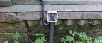
According to the current Rules for Electrical Installations, the secondary circuit must be located at the exit points of any type of building. Natural grounding conductors should be installed in place of the repeated grounding loop. The rules indicate some trimmers of metal structures that fit the contour of the rear
What kind of lighting do you prefer?
Built-in Chandelier
2.4.62. When crossing overhead lines with various structures, as well as with streets and squares of populated areas, the intersection angle is not standardized.
2.4.63. Crossing overhead lines with navigable rivers and canals is not recommended. If it is necessary to perform such an intersection, overhead lines must be constructed in accordance with the requirements of 2.5.268 - 2.5.272. When crossing non-navigable rivers and canals, the shortest distances from the overhead line wires to the highest water level should be at least 2 m, and to the ice level - at least 6 m.
2.4.64. The intersection and convergence of overhead lines with voltages up to 1 kV with overhead lines with voltages above 1 kV, as well as the joint suspension of their wires on common supports must be carried out in compliance with the requirements given in 2.5.220 - 2.5.230.
2.4.65. It is recommended to cross overhead lines (VLI) up to 1 kV with each other on cross supports; their intersection in the span is also allowed. The vertical distance between the wires of intersecting overhead lines (VLI) must be at least: 0.1 m on the support, 1 m in the span.
2.4.66. In places where overhead lines up to 1 kV cross each other, intermediate supports and anchor-type supports can be used.
When crossing overhead lines up to 1 kV in a span, the intersection location should be chosen as close as possible to the support of the upper intersecting overhead line, while the horizontal distance from the supports of the intersecting overhead line to the wires of the crossed overhead line at their greatest deviation should be at least 2 m.
2.4.67. With parallel passage and proximity of overhead lines up to 1 kV and overhead lines above 1 kV, the horizontal distance between them must be no less than those specified in 2.5.230.
2.4.68. Joint suspension of overhead line wires up to 1 kV and bare overhead line wires up to 20 kV on common supports is permitted subject to the following conditions:
1) Overhead lines up to 1 kV must be carried out according to the design climatic conditions of overhead lines up to 20 kV;
2) wires of overhead lines up to 20 kV should be located above wires of overhead lines up to 1 kV;
3) overhead line wires up to 20 kV, fixed to pin insulators, must have double fastening.
2.4.69. When hanging on common supports overhead line wires up to 1 kV and protected overhead line wires 6 - 20 kV, the following requirements must be met:
1) Overhead lines up to 1 kV must be carried out according to the design climatic conditions of overhead lines up to 20 kV;
2) the wires of overhead lines 6 - 20 kV should be located, as a rule, above the wires of overhead lines up to 1 kV;
3) the fastening of 6 - 20 kV overhead line wires on pin insulators must be reinforced.
2.4.70. When crossing an overhead line (VLI) with an overhead line with a voltage higher than 1 kV, the distance from the wires of the crossing overhead line to the crossed overhead line (VLI) must comply with the requirements given in 2.5.221 and 2.5.227.
The cross-section of the wires of the crossed overhead line must be taken in accordance with 2.5.223.
Expert opinion
It-Technology, Electrical power and electronics specialist
Ask questions to the “Specialist for modernization of energy generation systems”
Rules for the construction of electrical installations (PUE). Chapter 1.7. Grounding and protective measures for electrical safety (Sixth Edition) dated April 30, 1980. An isolation transformer is a transformer designed to separate the network supplying an electrical receiver from the primary electrical network, as well as from the grounding or grounding network. Ask, I'm in touch!
Issues covered in the PUE
Regulation of the operating procedure for various types of protective systems can be presented in the form of a certain set of requirements relating to the arrangement of individual structures.
According to them, the functional readiness of grounding loops, which include a whole set of structural elements, must be confirmed by the following technical data:
- Description of the design and composition of protective devices used in existing electrical installations;
- Formulas for calculating their sizes, as well as the resistance standards of grounding devices (GD);
- Tables with correction factors that allow you to introduce corrections for the quality and condition of the soil at the location of the contour (taking into account the material of individual elements);
- The procedure for organizing and conducting control tests available for grounding systems.
On a note. The presence of documented data on the performance characteristics and reliability of the functioning of the grounding loop of a private house, for example, will eliminate the possibility of electric shock to animals and residents.
When installing it, you are required to act in strict accordance with the PUE, as well as comply with all requirements regarding the operation of this protective device.
Types of material (profiles)
According to the requirements of the PUE, which contain instructions on what the resistance of current flow in the ground should be, in most cases this indicator is set at a level of no more than 4 ohms. To obtain this value, you usually have to make a lot of effort to adhere to the same technology requirements.
First of all, this concerns the materials used in assembling the grounding loop, selected based on the following conditions:
- When choosing pins, preference should be given to ferrous metal blanks;
- The most commonly used rod is a standard size of 16-20 mm or a corner with parameters 50x50x5 mm and a metal thickness of about 5 mm;
- It is not allowed to use reinforcement as circuit elements, since it has a hardened surface that affects the normal flow of current;
- For these purposes, it is pure rod that is suitable, and not its reinforcement substitute.
Note! For areas with dry summers, thick-walled metal pipes are best suited, the lower end of which is flattened into a cone, and then several holes are drilled in this part of the pipe. According to the provisions of the PUE, before placing them in the ground, holes of the required length are first drilled, since driving them manually is quite problematic
In the case of a particularly dry summer and a sharp deterioration in the parameters of the ground electrode, a concentrated saline solution is poured into the hollow parts of the pipes, which makes it possible to obtain the resistance that should be in accordance with the requirements of the PUE. The length of pipe blanks is selected within 2.5-3 meters, which is quite enough for most Russian regions
According to the provisions of the PUE, before placing them in the ground, holes of the required length are first drilled, since driving them in manually is quite problematic. In the case of a particularly dry summer and a sharp deterioration in the parameters of the ground electrode, a concentrated saline solution is poured into the hollow parts of the pipes, which makes it possible to obtain the resistance that should be in accordance with the requirements of the PUE. The length of pipe blanks is selected within 2.5-3 meters, which is quite enough for most Russian regions.
This type of profile blanks has special requirements regarding the order of their placement in the soil and consists of the following:
- Firstly, the pipe elements of the protective circuit must be placed at a depth exceeding the soil freezing level by at least 80-100 cm;
- Secondly, in particularly dry areas, approximately a third of the length of the ground electrode should reach wet soil layers;
- Thirdly, when fulfilling the second condition, one should focus on the peculiarities of the location of the so-called “groundwater” in a given region. If they are located at a significant depth, according to the rule formulated in the provisions of the PUE, it will be necessary to prepare longer pipe sections.
The type and profile of the pin blanks used in the construction of the grounding switch can be found in the figure below.
Acceptable pin profiles
In practice, in most regions of Russia, a steel corner and a strip of the same metal are usually used. In order to obtain more accurate parameters of the grounding elements used, geological survey data will be required. If this information is available, it will be possible to involve specialists in calculating the parameters of the ground electrode.
How grounding works and how it works
The main function of grounding is to connect all electrical consumers to the protection circuit using a special grounding wire. In total, there are 3 different grounding systems, but for a private house or cottage, the system version marked TN - 5 is most often used. In such a situation, neutral and ground are carried out with different wires.
As a result, when there is a current leak or an insulation breakdown in electrical appliances, a voltage dangerous to humans is transmitted through the wire to the protective circuit
The standard for installation and arrangement of the grounding loop depends on the resistance indicators. The quantitative indicator of this parameter is influenced by:
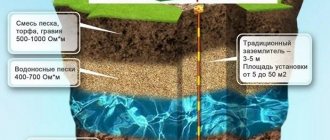
- type of soil;
- soil moisture parameters;
- depth to which grounding conductors are immersed;
- how many ground electrodes are in the circuit;
- What are the electrodes and all components made of?
According to SNiP standards, the contour must be made in the shape of an equilateral triangle. The ground loop is calculated based on the depth of the electrodes and soil parameters.
The type of soil determines the level of resistance to the spreading of fault circuit currents. The best option is peat bog, loamy soil and clay soil with close groundwater. Rocky soil and monolithic rocks have the worst parameters.