Let's delve into the topic
Consumers are powered from the low voltage windings of a step-down transformer, which is the most important component of the operation of a transformer substation. The connection between the substation and subscribers is as follows: a common conductor is supplied to the consumers, extending from the point of connection of the transformer windings, called the neutral, along with three conductors, which are the terminals of the remaining ends of the windings. In simple terms, each of these three conductors is a phase, and the common one is zero.
Between phases in a three-phase power system, a voltage called line voltage occurs. Its nominal value is 380 V. Let's define phase voltage - this is the voltage between zero and one of the phases. The rated phase voltage is 220 V.
An electrical power system in which the neutral is connected to ground is called a “solidly grounded neutral system.” To make it absolutely clear even for a beginner in electrical engineering: “ground” in the electrical power industry means grounding.
The physical meaning of a solidly grounded neutral is as follows: the windings in the transformer are connected in a “star”, and the neutral is grounded. The neutral acts as the combined neutral conductor (PEN). This type of connection to the ground is typical for residential buildings dating back to Soviet construction. Here, in the entrances, the electrical panel on each floor is simply nulled, and a separate connection to the ground is not provided
It is important to know that connecting the protective and neutral conductors to the panel body at the same time is very dangerous, because there is a possibility that the operating current will pass through zero and its potential will deviate from zero, which means the possibility of electric shock
For houses belonging to a later construction, the same three phases, as well as separated neutral and protective conductors, are supplied from the transformer substation. The electric current passes through the working conductor, and the purpose of the protective wire is to connect the conductive parts with the grounding loop existing at the substation. In this case, in the electrical panels on each floor there is a separate bus for separate connection of phase, neutral and grounding. The grounding bus has a metal connection with the body of the shield.
It is known that the load among subscribers must be distributed evenly across all phases. However, it is not possible to predict in advance what power will be consumed by a particular subscriber. Due to the fact that the load current is different in each individual phase, a neutral offset appears. As a result, a potential difference arises between zero and ground. In the case where the cross-section of the neutral conductor is insufficient, the potential difference becomes even greater. If the connection with the neutral conductor is completely lost, then there is a high probability of emergency situations in which in phases loaded to the limit, the voltage approaches zero, and in unloaded phases, on the contrary, tends to a value of 380 V. This circumstance leads to complete breakdown of electrical equipment . At the same time, the housing of electrical equipment becomes energized, dangerous to the health and life of people. The use of separated neutral and protective wires in this case will help avoid such accidents and ensure the required level of safety and reliability.
Finally, we recommend watching useful videos on the topic, which provide definitions of the concepts of phase, zero and grounding:
We hope you now know what phase, neutral, and ground are in electrical engineering and why they are needed. If you have any questions, ask our specialists in the “electrician” section!
We also recommend reading:
What is the difference between a phase conductor and a neutral conductor?
The purpose of the phase cable is to supply electrical energy to the desired location. If we talk about a three-phase electrical network, then there are three current-supply wires per single zero wire (neutral). This is due to the fact that the flow of electrons in a circuit of this type has a phase shift of 120 degrees, and the presence of one neutral cable in it is quite sufficient. The potential difference on the phase wire is 220V, while the zero wire, like the ground wire, is not energized. On a pair of phase conductors the voltage value is 380 V.
Line cables are designed to connect the load phase to the generator phase. The purpose of the neutral wire (working zero) is to connect the zeros of the load and the generator. From the generator, the flow of electrons moves to the load along linear conductors, and its reverse movement occurs through neutral cables.
The neutral wire, as mentioned above, is not energized. This conductor performs a protective function.
The purpose of the neutral wire is to create a chain with a low resistance value, so that in the event of a short circuit, the current is sufficient to immediately trigger the emergency shutdown device.
Thus, damage to the installation will be followed by its rapid disconnection from the general network.
It will be interesting➡ Protective grounding. Main and additional potential equalization systems. Third party conductive parts. Grounding in a private house
In modern wiring, the sheath of the neutral conductor is blue or light blue. In old circuits, the working neutral wire (neutral) is combined with the protective wire. This cable has a yellow-green coating.
Depending on the purpose of the power transmission line, it may have:
- Solidly grounded neutral cable.
- Insulated neutral wire.
- Effectively grounded neutral.
The first type of lines is increasingly used in the design of modern residential buildings.
In order for such a network to function correctly, the energy for it is generated by three-phase generators and is also delivered through three phase conductors under high voltage. The working zero, which is the fourth wire, is supplied from the same generator set.
Visually about the difference between phase and zero in the video:
Multi-color phase in assortment
It is through the phase that the voltage passes
This means that you need to be especially careful when working with this type of cable. This wire is designated by the letter l in electrical engineering, which is an abbreviation of the word Line
In a three-phase network, the following conductor designations are used: l1, l2, l3. Sometimes English letters are used instead of numbers. Then it turns out la, lb, lc.
A lot can be said about the color designation of phases. One thing is clear: the phase conductor can be any color except yellow, green and blue. However, in Russia they found their answer to the question of what color the phase is. According to GOST R 50462-2009, it is recommended to use black or brown. However, this standard is only advisory. Therefore, manufacturers do not limit themselves to certain color boundaries. For example, red and white are much more common than brown. Bright colors - pink, turquoise, orange, purple are also often present in the set
It is believed that bright colors will protect from danger and attract the attention of the master. Still, tension is no joke
Using information about wiring colors during installation
Imagine if all cables were the same color. You open the switchboard - and how to find the required wire? Only with the help of a tester - a special indicator screwdriver. By touching the end of the bare wire, see if the indicator lights up - this means that the wire is phase. If the indicator does not light, it is zero.
Knowing the color codes speeds up the search time for the cable you need, and also ensures safety when working with the electrical network.
Basic definitions on the topic General grounding
Protective grounding is the connection of conductive parts of equipment with the ground of the Earth through a grounding device in order to protect a person from electric shock. Grounding device is a combination of a ground electrode (that is, a conductor in contact with the ground) and grounding conductors. Common wire is a conductor in the system against which potentials are measured , for example, the common wire of the power supply unit and the device. Signal grounding is a connection to the ground of the common wire of the signal transmission circuits. The signal ground is divided into digital ground and analog ground. Signal analog ground is sometimes divided into analog input ground and analog output ground. Power ground is a common wire in the system connected to the protective ground through which a large current flows. Solidly grounded neutral is the neutral of a transformer or generator, connected to the ground electrode directly or through low resistance. Neutral wire is a wire connected to a solidly grounded neutral. An insulated neutral is a neutral of a transformer or generator that is not connected to a grounding device. Grounding is a connection of equipment to a solidly grounded neutral of a transformer or generator in three-phase current networks or to a solidly grounded terminal of a single-phase current source.
Grounding of automated process control systems is usually divided into:
- Protective grounding.
- Working ground, or functional FE.
Ground color
The color of the grounding wire, “ground”, is almost always indicated by yellow-green color
. Windings that are either completely yellow or light green are less common. The wire may be marked “PE”. You can also find green-yellow wires marked “PEN” and with blue braiding at the ends of the wire at the fastening points - this is grounding combined with neutral.
In the distribution panel (DP) it should be connected to the grounding bus, to the housing and the metal door of the panel. As for the distribution box, the connection goes to the grounding wires from the lamps and from the grounding contacts of the sockets. The ground wire does not need to be connected to the RCD (residual current device), therefore RCDs are installed in houses and apartments, since electrical wiring is usually carried out with only two wires
Grounding designation on the diagrams:
Conventional ground(1) Clean ground(2) Safety ground(3) Chassis ground(4) DC ground(5)
What is the difference between grounding
Additional information about finding the ground, phase, neutral wire
Let's add another method - it is prohibited by industry. A light bulb in a socket with two exposed wires. Using the tool, the phase is found, and the wire can be short-circuited to ground. You cannot use water, gas, sewer pipes or other engineering structures. According to the rules, the cable antenna braid is equipped with grounding (grounding). With respect to it, you can use a tester (a light bulb in a socket prohibited by standards) to find the phase.
For determined people, we recommend fire escapes and steel tires for lightning rods. You need to clean the metal until it shines, call the phase phase
Please note that not all fire escapes are grounded (although they must be), lightning rod buses are 100%. If you discover such blatant arbitrariness, you can contact the management organizations; if there is no response, knock (Russians call human rights activists informers) to government agencies
Indicate a violation of the rules for protective grounding of buildings.
How to find zero and phase
At home, even without special instruments and devices, it is possible to determine in a regular outlet which of the two wires is a phase and which is a zero. In this case, an electric lamp or an indicator screwdriver is used.
Checking with an electric lamp
To find zero and phase, just take an ordinary socket with a light bulb and screw two wires into its regular places. Then connect one of these wires to the grounding blades in the socket, and the second to either of the two power connectors.
The phase connector will be the one to which the light bulb will light up when connected. This happens because, according to the Electrical Installation Rules (PUE), in the input electrical panel, the neutral wires of all sockets must be connected to the ground wires of the same sockets. A separate earth bus must be connected to a protective ground loop. This is what ensures the presence of a reliable zero in the entire energy supply chain of the house.
Note! It is permissible to carry out such procedures independently only in cases where there is nowhere to wait for qualified help, as well as in the event of an emergency (fire, short circuit, person under voltage). Do not forget that electric current is very dangerous. Don't risk your health and your life over a light bulb!
Indicator screwdriver
In order to determine the phase in an alternating current network with a voltage of 220V - 230V, you can use a household voltage indicator - an indicator screwdriver. It is sold in almost any hardware store and is (depending on the design) very inexpensive.
As a rule, such tools do not have instructions for use, so in order to avoid electrical injury, you should remember a few simple rules that apply to any tool that comes into contact with live parts:
- Use the tool only for its intended purpose (it is prohibited to use the voltage indicator - indicator screwdriver - as an ordinary screwdriver for tightening/unscrewing screws, self-tapping screws, screws, etc.)
- Before using the tool, you should carefully consider the condition of the insulation on the handle and tip (applicable to any screwdrivers, including indicator ones). Do not use the device under any circumstances if the insulating coating is chipped or missing altogether.
- It is necessary to check the functionality of indicator devices on electrical installations that are known to be energized (for example, in an extension cord into which a working electrical appliance is connected).
If there is any doubt about the functionality of the indicator, it should be considered faulty and the electrical installation functional.
There are also more accurate and safer instruments for determining the presence of voltage in the network - these are multimeters, current clamps, volt-ampere phase meters (VAF) and others.
Find the neutral wire in the apartment
According to the rules, the housing of the access panel is grounded. It is carried out using a solid-sized terminal, tightened with a powerful bolt in old-built houses; it will be easier for residents of modern buildings to navigate by the number of cores. The zero bus has the largest number of connections, the phases are separated into apartments (good electricians hang up stickers A, B, C; evil ones don’t). We can easily follow the layout of circuit breakers and meters.
230 volt UK plug
In each case, the common wire will be zero. Color does not play a decisive role. Although according to standards, modern cables are equipped with colored insulation
Please note - if the house is equipped with grounding, there will be at least 5 cores at the input. The panel body is mounted on a yellow-green
The neutral wire will serve to drain the operating current from the devices (closes the circuit). Merging branches on the consumer side is prohibited. Here are three rules to help you understand the entrance panel (please note, according to the rules, the tenant should not show his nose there at all - we have warned):
- The circuit breaker breaks the phase. There are two-pole models; they are used relatively rarely for rooms with particular danger (bathroom). Therefore, by the position of the wire you can tell: this is a phase. Then you can turn off the machine and ring the wire on the side of the apartment. It will definitely give the phase position.
- The voltage between the neutral wire and any phase is 230 volts. Based on the key characteristic, we will select a vein that gives the specified difference to another. The spread between phases is 400 volts. The percentage values are 10 percent higher; Russian networks are trying to meet European standards.
- We use current clamps to measure the values on the conductors. For each phase there will be a certain value, the sum of which (in three) should flow back to the network via zero (or a suitable phase). Grounding is rarely used; the current here will be close to zero if the branches are evenly loaded. The place where the value is greatest is traditionally the neutral conductor.
- The grounding terminal of the distribution board is visible. The sign will help you find the neutral wire in houses with NT-CS. In other cases, grounding is supplied here.
Plus and minus symbol
The standards used will vary depending on what country the wiring is in, the type of electricity, and other factors.
Exploring the different options that can be used in a given situation is important for workplace safety
Plus and minus
When connecting to a DC source, 2 or 3 wires are usually used. The coloring looks like this:
- Red - “+” plus wire;
- Black - “-” minus wire;
- White or gray - ground wire.
Note! Reliable and legible markings must be provided at the interface where new and old versions of the fixed wiring color code exist. The warning notice must also be prominently displayed on the relevant switchboard controlling the circuit
https://youtube.com/watch?v=sNDMjqB2NYU
Where did zero come from and what does it look like?
If we consider planet Earth from the point of view of electrical engineering, then it is a spherical capacitor. It has three elements:
- The earth's surface has a negative potential.
- The ionosphere is a layer of the atmosphere that receives and partially scatters solar radiation. She has positive potential.
- A gas atmosphere that has dielectric properties and acts as a lining.
The potential difference between the plates of this global capacitor is 300 thousand volts. It decreases as it approaches the surface. So, at an altitude of 100 meters its value is 10 thousand volts.
Why do we consider the Earth's potential to be zero, because in fact it has a completely material value, albeit with a negative sign? This question is worth asking the scientists of the 18th or 19th centuries who laid the foundations of electrical engineering.
For example, the English physicist Michael Faraday. So it was more convenient for them to measure the strength of the electromagnetic field - taking the Earth as the reference point (zero). This technique is used in many branches of science. For example, in thermodynamics. In it, the temperature at which the movement of electrons in the atomic structure of any substance stops is taken as absolute zero.
This is the so-called Kelvin scale, which differs from another temperature measurement system - it was proposed by Anders Celsius - by 273 degrees with a minus sign.
So, electric zero is a conventional concept that is used in relation to any object with a negative potential. It can be obtained in three ways:
- Having joined the earth's firmament, which is why the concept of “grounding” came about.
- The crystal lattice of all metals has a negative charge of varying magnitude, which determines the degree of their electrochemical activity. Therefore, it is enough to attach to a metal object of large mass and volume. The last two conditions are mandatory, since the body must have an electrical capacity comparable to that of the Earth. This is called working ground.
- By connecting conductors with alternating current flowing through them so that at a common point the sum of their vector addition is equal to zero (the so-called star circuit), which is why it was called neutral. This is the basis of a technique called zeroing in electrical engineering.
Zero break, zero burnout - consequences!
Rating: 5 / 510Zero breakage, zero burnout - consequences!
"What doesn't kill us makes us stronger." Controversial statement.
It definitely cannot be classified as electricity, because the effect of current on the human body depends on a huge number of factors, from body temperature to the presence of diseases.
Of course, no one is immune from being caught under voltage. But you can easily reduce the likelihood of such an incident. In this article we will tell you in detail about the break or burnout of the zero, the consequences of this, and protective measures.
As you know, three power supply circuits for electrical receivers are most widespread: triangle, star and star with zero. The first two are used mainly where the load is distributed evenly across three phases.
Advice
For example, the windings of electric motors or transformers are connected using such circuits. In residential and public buildings I use a “star-zero” connection scheme - a regular star with a neutral wire.
What is the reason for its use?
The fact is that in the residential and public sector the load is single-phase: one apartment (floor or private house) is powered from one phase, the next from the second, another from the third, then in the second circle. Since three phases of voltage are suitable for the input panel, the number of apartments in a house or entrance is a multiple of three.
This is an attempt to achieve uniform loading of the three phases. However, it is impossible to ensure that all apartments turn on and off electrical appliances at the same time. To keep the three-pointed voltage star (left) symmetrical, a neutral conductor is used.
The unevenness of electrical loads in the form of electric current literally flows into the ground along the neutral wire (current in the figure).
Photo 1: email charts. loads in the form of electric current
Now apartments and offices are filled with consumer electronics - computers, uninterruptible power supplies, LED lamps. These devices create high frequency currents, which also flow into the ground through the neutral wire.
Currents heat the place of poor contact - and there is the greatest resistance. When heated, the resistance increases even more, this, in turn, leads to greater heating, and as a result, the neutral wire can burn out.
Consider this very real case; The same reasoning will apply if the neutral wire breaks for some other reason.
Photo 2: burnt zero
The wire can burn out in different places, which can be reduced to two cases:
1) general break: in a three-phase floor panel or input panel;
2) an individual break: in the circuit breaker protecting the apartment, or in the distribution box, or in the socket.
In the second case, two options are possible: either the voltage in the apartment/outlet will simply disappear, or the voltage of 220-230 V will be even where it is not expected at all.
An interesting picture may emerge: electrical appliances will not work, and the multimeter will show that there is no voltage in the outlet. In fact, the voltage will be both in phase and at zero.
Voltage from phase to zero can be transmitted through the electrical circuit of some load connecting phase and zero, be it a light bulb or a charger.
note
And if the protective grounding circuit in the apartment is assembled incorrectly, a voltage of 220 V may appear on the body of the microwave or washing machine. Again, a regular circuit breaker will not notice this. Protection of equipment from the consequences of a break is achieved by installing a voltage control relay in the panel.
Photo 3: voltmeters
Let's move from words to numbers. Let us denote the voltage at the point of break (or connection) of the neutral wire as , - the resistance of phase X or the neutral wire N. - the current in phase X or the neutral wire N. All these quantities are complex, i.e.
in calculations it is necessary to take into account a phase shift of 120°.
Calculations of currents and voltages in normal mode (substitute the resistance of the neutral wire instead) and in the event of a break in the zero ( ) are carried out in this order: look for the voltage at the zero point, calculate the “distorted” phase voltage and current in the phase.
In normal mode, the current at “zero” is equal to the sum of the complex phase currents.
Social buttons for Joomla
Why is zero needed in electricity?
Zero completes the electrical circuit. Without this wire, there can be no electric current in the circuit, which provides the power to power household appliances. Essentially, the neutral wire is ground.
Where does zero come from in the electrical network?
The zero originates from the complete 6(10)/0.4 kV transformer substation, where the transformer is connected to the ground loop by its zero bus. Initially, it is the earth that is a conductor with zero potential, and this is why many people confuse zero with earth. The overhead power line (overhead power line), leaving the transformer substation, has 4 wires - 3 phases and a neutral, which at the beginning of the line is connected to the neutral of the transformer. Along the overhead line, re-grounding is carried out through one support, which additionally connects the zero of the line to the ground, which provides a more complete connection of the “phase-zero” circuit so that the end consumer has at least 220V in the outlet.
Phase, neutral and ground in the wire
Why is zero needed?
The main purpose of the neutral wire is to close the circuit to create electric current for the operation of any electrical appliance. After all, in order for current to appear, a potential difference between the two wires is necessary. This is why it is called zero because the potential on it is zero. Hence the voltage level is 220V - 230V.
Let's understand the basic terms
Everyone encounters such terms as “phase” and “zero” in their lives every day. All of them are closely related, because they relate to electricity, and this is something without which the life of a modern person is unthinkable. To understand their nature and more or less learn to understand electrics, you should first understand a number of fundamental concepts.
Let's start with the basics
Electric charge is a characteristic that determines the ability of various bodies to be a source of an electromagnetic field. The carrier of such waves is the electron. By creating an electromagnetic field, you can “force” electrons to move. This is how current is generated.
Current is a clearly directed movement of electrons along a metal conductor under the influence of an existing field.
Types of current
The current can be constant or alternating. A current that does not change in value over a period of time is a current of constant value. A current, the magnitude of which, like the direction, changes over time, is called variable.
Constant current sources - batteries, batteries, and so on. Alternating current is “suitable” for household and industrial sockets in homes and businesses. The main reason for this lies in the fact that this type of current is much easier to obtain physically, convert to different voltage levels, and transmit through electrical wires over vast distances without significant losses.
Basic characteristic of alternating current
Alternating current is usually a sine wave, or sinusoidal current. It can be characterized as follows: first it increases in one direction, reaching its maximum value (amplitude), then it begins to decline. At some point in time it becomes equal to “0” and then begins to increase again, but in a completely opposite direction.
"Phase", "zero" and "ground"
The simplest case of an electrical circuit through which a sinusoidal current moves is a single-phase circuit. It consists, as a rule, of three electrical cables: along one of them, electricity approaches devices and lighting elements, and through the second, it “leaves” in the opposite direction - away from the consumer. The third conductor is the “ground”.
The wire through which electricity reaches electrical consumers is called a phase, and the cable used for return movement is called zero.
The most efficient network for transmitting electric current is a three-phase system. It includes three phase cables and one return cable - zero. This type of current is suitable for all residential areas. Immediately before entering the apartment, the electric current is divided into phases. Each phase is “assigned” one zero. The advantages of such a system are that with a balanced load, the current through zero (and in such a system there is only one - common) is zero.
To avoid mixing up the wires and preventing a short circuit, each wire is painted a different color. However, the color of the wire does not guarantee its purpose!
The “earth” does not carry any electrical load, but serves as a kind of safety element. At that moment, when something in the power supply system gets out of control, the ground wire will prevent electric shock - it will “drain” all excess voltage, that is, it will be discharged to the ground.
Phase and zero: their meaning in the power supply network
Electricity is supplied to consumer sockets from substations, which reduce the incoming voltage to 380 V. The secondary winding of such a transformer has a “star” connection - its three contacts are connected to each other at the “0” point, the remaining three outputs go to the “A” / “B” terminals "/"WITH".
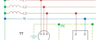
The wires connected at point “0” are connected to “ground”. At the same point, the conductor is divided into “zero” (indicated in blue) and a protective “PE” cable (yellow-green line). This model of wiring is used in all houses currently being built. It is called the “TN-S” system. According to this diagram, three phase cables and two indicated zeros are suitable for the distribution equipment of the house.
In houses, enterprises and buildings of old construction there is often no “PE” conductor and therefore the circuit turns out not to be five-wire, but four (it is designated as “TN-C”).
All electrical wires from the substations are connected to the panel, forming a three-phase system. Then there is a division into separate entrances. Each of the entrance apartments is supplied with only one phase voltage - 220 V (wires “O” / “A”) and a protective “PE” cable.
With this scheme, the entire load on the power supply system is distributed evenly, since on each floor of the house specific panels are wired and connected to a specific 220 V power line.
The supply voltage circuit is a “star”, which exactly repeats all the vector characteristics of the supply substation. When there are no consumers in the sockets, no current flows in this circuit.
This connection scheme has been worked out for years. It confirmed its right to use by being recognized as the optimal of all existing ones. However, in it, as in any device, mechanism or device, all kinds of breakdowns and malfunctions may periodically appear. As a rule, they are associated with poor quality electrical connections or complete cable breaks in some places in the circuit.
Cases of breaks in the conductive circuit
If a zero/phase break occurs inside a single apartment, then the connected device, as a result, will not function.
A similar situation will arise if the contacts of the wires of any of the phases supplying the access panel are broken. In this case, all apartments receiving power from this power line will not receive electricity. At the same time, in the two remaining circuits the devices will function as before.
From these diagrams it is clear that a complete power outage in apartments is associated with a break in one of the wires. This does not lead to damage or failure of the devices. The most serious situation is a break between the grounding loop and the central connection point of all consumers.
In this case, the entire electric current stops flowing along the working zero to the “ground” (AO, VO, CO) and begins to move along the path AB/BC/CA to which 380 V is supplied.
A “phase imbalance” occurs. In phases with a higher load, the voltage will be less, and with a lower load, more and can reach significant values, close to 380 V. This will cause damage to the insulating materials, heating and failure of the equipment. A system of protection against overloads and high voltages mounted in apartment panels allows you to prevent such cases and protect expensive equipment.
Basic concepts.
Current strength is a scalar physical quantity equal to the ratio of the charge passing through the conductor to the time during which this charge passed.
where
I is the current strength, q is the amount of charge (amount of electricity), t is the charge transit time.
Current density is a vector physical quantity equal to the ratio of the current strength to the cross-sectional area of the conductor.
where
j
is
the current density
,
S
is
the cross-sectional area of the conductor.
The direction of the current density vector coincides with the direction of motion of positively charged particles.
Voltage
-
a scalar physical quantity equal to the ratio of the total work of Coulomb and external forces when moving a positive charge in an area to the value of this charge.
where A is the total work of external and Coulomb forces, q is the electric charge.
Electrical resistance is a physical quantity that characterizes the electrical properties of a section of a circuit.
where ρ is the resistivity of the conductor, l is the length of the conductor section, S is the cross-sectional area of the conductor.
Conductivity is the reciprocal of resistance
where G is conductivity.
Operating principle of AC network
The AC network is divided into two components: the operating phase and the empty phase. The working phase is sometimes simply called the phase. The empty phase is called the zero phase or simply zero. It serves to create a continuous electrical network when connecting devices, as well as to ground the network. And the operating voltage is supplied to the phase.
When turning on an electrical appliance, it does not matter which phase is working and which is empty. But when installing electrical wiring and connecting it to the general house network, this needs to be known and taken into account. The fact is that the installation of electrical wiring is done using either a two-core cable or a three-core cable. In a two-core one, one core is the working phase, the second is zero. In a three-wire system, the operating voltage is divided into two cores. This results in two working phases. The third core is empty, zero. The general house network is made of a three-core cable. The general electrical wiring diagram in a private house or apartment is also mainly made from a three-core wire. Therefore, before connecting apartment wiring, you need to determine the working and zero phases.
Sources of interference on the ground bus
All interference affecting cables, sensors, actuators, controllers and metal automation cabinets, in most cases, also flows through the grounding conductors, creating a parasitic electromagnetic field around them and a drop in the interference voltage on the conductors.
Sources and causes of interference can be lightning, static electricity, electromagnetic radiation, “noisy” equipment, a 220 V power supply with a frequency of 50 Hz, switched network loads, triboelectricity, galvanic couples, the thermoelectric effect, electrolytic processes, conductor movement in a magnetic field, etc. In industry, there is a lot of interference associated with malfunctions or the use of uncertified equipment. In Russia, the level of interference is regulated by standards - GOST R 51318.14.1, GOST R 51318.14.2, GOST R 51317.3.2, GOST R 51317.3.3, GOST R 51317.4.2, GOST 51317.4.4, GOST R 51317.4.11, GOST R 51522, GOST R 50648. At the design stage of industrial equipment, in order to reduce the level of interference, they use a low-power element base with minimal speed and try to reduce the length of conductors and shielding.
Conclusion
The main distinguishing feature of “zero” and “ground” is their purpose. “Zero” together with the phase is intended to power electrical appliances, and “ground” is to protect people and animals from electric shock if a breakdown occurs. The working “zero” can be used as a “ground” if the conditions of PUE 1.7.83 are not violated. We recommend laying the wiring immediately with a grounding conductor, which eliminates the need to use the “zero” for other purposes.
Test your electrical knowledge:
- Why is there 220 V between phase and zero, and 380 V between phases?
- Why is the voltage in the networks 110 V in the USA, and 220 V in Russia?
Phase and zero concepts and differences
There is such a thing as tension. This word means the degree of electric field strength at a given point or circuit. Otherwise it is called potential. In very simple words, this is a kind of piston that gives an impetus to electrons so that they pass through the wires and light a light bulb in a chandelier.
In the common circuit (phase zero), the one that comes to the chandelier or socket, there are two wires. One of them is a phase. It is this wire that is live. A phase in electrical engineering is comparable to a positive in a car - it is the main power supply for the network.
Phase, neutral, ground in the socket
Zero is a wire that is not energized (this is exactly what distinguishes zero from phase). It is not overloaded during the power take-off process, but, nevertheless, electric current also flows through it, only in the direction opposite to the phase one. In the absence of voltage, it is safe in terms of electric shock to a person.
What happens if you confuse zero with ground?
If the grounding is working properly and is carried out in accordance with all requirements, the error may not be suspected for many years. I have come across incorrectly connected electric stoves many times since Soviet times. However, you should not turn a blind eye to these mistakes:
1. Electricity metering devices will not work correctly, because of this you can get a hefty fine from the power industry when everything becomes clear.
2. When installing differential switches (RCDs) or differential circuit breakers, their correct operation is impossible. These devices will be turned off all the time.
3. Grounding will cease to fulfill its main function - to protect a person from electric shock. In addition, this can become the very cause of lesions.
4. If the grounding in a private house is “weak,” it will quickly fail and, in any case, repairs will have to be made.
Grounding conductors
The most common color designation for grounding insulation is a combination of yellow and green. The yellow-green coloring of the insulation has the form of contrasting longitudinal stripes. An example of a ground electrode is shown in the image below.
Yellow-green coloring of the ground electrode
However, occasionally you can find either completely yellow or light green color of grounding insulation. In this case, the letters PE may be marked on the insulation. In some brands of wires, their yellow and green color along the entire length near the ends with the terminals is combined with a blue braid. This means that the neutral and grounding in this conductor are combined.
In order to clearly distinguish between grounding and grounding during installation and also after it, different colors are used to insulate the conductors. Grounding is performed with light blue wires and conductors connected to a bus marked with the letter N. All other conductors with insulation of the same blue color must also be connected to this zero bus. They should not be connected to switch contacts. If sockets with a terminal marked with the letter N are used, and at the same time there is a zero bus, there must be a light blue wire between them, respectively, connected to both of them.
The nuances of manual color marking
Color marking of wires using cambric
Manual marking is used when using wires of the same color in old buildings. Before starting work, a diagram with the color values of the conductors is drawn up. During the installation process, you can mark current-carrying conductors:
- standard cambrics;
- cambrics with heat shrinkage;
- insulating tape.
The rules allow the use of special marking kits. The installation points for markers to indicate zero and phase are indicated in the PUE and GOST. These are the ends of the wire and where it connects to the bus.
Specifics of marking a two-core wire
Heat shrink tube for wires
If the cable connection to the network has already been made, you can use an indicator screwdriver. The difficulty in using the tool lies in the inability to determine multiple phases. You will need to test them with a multimeter. To prevent confusion, you can color-code the electrical conductor:
- choose heat-shrinkable tubes or electrical tape to indicate zero and phase;
- work with conductors not along their entire length, but only at the junctions and joints.
The number of colors is determined by the scheme. The main thing when creating it is not to get confused, not to use yellow, green or blue markers for the phase. It can be marked in red or orange.
Three-wire wire marking
Using a multimeter, you can determine the location of the phase, zero, and grounding.
To find the phase, grounding, and zero in a three-wire wire, it is advisable to use a multimeter. It is set to alternating voltage mode and carefully touches the phase with probes, then touches the remaining cores. The tester's performance should be recorded and compared. In the phase-ground combination, the voltage will be lower than in the phase-zero combination.
After clarifying the lines, you can make markings. The corresponding colors will help you understand whether the phase is L or N. For zero it will be blue or blue, for plus it will be any other.
The procedure for marking a five-wire system
Electrical wiring from a three-phase network is carried out only with a five-core cable. Three conductors will be phase, one will be neutral, one will be protective ground. Color coding is applied in accordance with regulatory requirements. For protection, a yellow-green braid is used, for zero - blue or cyan, for phase - from the list of permitted shades.
How to mark combined wires
To simplify the wiring process, cables with two or four cores are used. The defensive line here connects to the neutral. The letter index of the wire is PEN, where PE denotes the grounding conductor, and N is the neutral conductor.
According to GOST, special color markings are used. The length of the combined cable will be yellow-green, and the tips and connection points will be blue.
Highlight the main points of problem areas with cambrics or electrical tape.
How to distinguish phase, zero, ground
The easiest way to determine the purpose of the conductors is by color marking. In accordance with the standards, the phase conductor can have any color, the neutral can be blue, and the ground can be yellow-green. Unfortunately, when installing electrics, color coding is not always observed. We must not forget the likelihood that an unscrupulous or inexperienced electrician can easily confuse phase and zero or connect two phases. For these reasons, it is always better to use more precise methods than color coding.
You can determine the phase and neutral conductors using an indicator screwdriver. When the screwdriver comes into contact with the phase, the indicator will light up, as electric current passes through the conductor. Zero has no voltage, so the indicator cannot light up.
You can distinguish zero from ground using a dial tone. First, the phase is determined and marked, then with a continuity probe you need to touch one of the conductors and the ground terminal in the electrical panel. Zero will not ring. When you touch the ground, a characteristic sound signal will be heard.
If you find an error, please select a piece of text and press Ctrl+Enter.
How to determine ground, zero and phase on wires if there are no markings
It is more difficult to determine in practice than in theory. Not all manufacturers comply with the standards. Therefore, when laying a two-phase 220 V network with grounding, you have to use a VVG cable with blue, brown and red colors. Combinations may be different, but without complying with regulatory requirements.
For your information. In old wiring from “Soviet times” there is no color marking. Identical white (gray) shells do not allow the purpose and correspondence of the lines to be known by simple visual inspection.
To avoid problems, it is recommended to carry out installation work using the same type of cable products. When color coding is not available, it should be created at the joints using insulating tape or heat shrink tubing. The latter option is preferable, as it is designed to maintain integrity for a long time.
Below are methods for determining phase and neutral wires with the advantages and disadvantages of each option. In any case, first clarify the network parameters. In old houses, for example, a two-wire connection scheme with a single working and grounding conductor is often used.
The figure shows a modern network with separate grounding and working zero connections. It is possible to connect three- and single-phase loads.
Determining the phase using an indicator screwdriver
Touching the tip of such a device to the phase wire closes the current circuit. This is accompanied by the warning lamp or LED lighting up. A built-in resistor limits the current to a safe level.
Advantages of the indicator:
- minimum cost;
- compactness;
- reliability;
- durability;
- autonomy;
- good protection from adverse external influences.
The disadvantage is the limited measurement accuracy. Under certain conditions, false positives cannot be ruled out.
Determination of ground, zero and phase using a test lamp
To reproduce this technology, you need to prepare a simple design. An incandescent lamp designed for the appropriate mains voltage is screwed into a standard socket. Connect wires of sufficient length to perform work operations in a specific location.
Next, connect one of the wires to the known zero line. Others sequentially check other cable cores. Lighting of the lamp indicates the presence of a phase.
Using a measuring device
When checking a 220 V household network, you do not need to know how to determine the polarity. The power supply is organized using alternating current, so set the multimeter switch to the appropriate position. Touching the phase-zero (phase-ground) wires with the probes is accompanied by an indication of the corresponding voltage (≈220 V). The potential difference between the neutral conductor and ground is minimal.
For your information. When checking an old two-wire circuit, one of the probes touches the reinforcement in a concrete slab, a radiator of a heating system, or another grounded element of a building structure.
When switching to constant voltage, the multimeter will show where the plus and minus are. In the absence of reliable information about the electrical parameters in the circuit, they begin with the maximum measurement range with a sequential transition to smaller values with insufficient accuracy.
Such a “device” is useful for testing DC circuits in the absence of specialized measuring instruments. Bubbles near the negative wire are the release of hydrogen during the electrolysis reaction. The area near the plus will take on a greenish tint after a few minutes.
Using LED
You can create a control device with your own hands by analogy with an indicator screwdriver. Instead of a light bulb, install AL 307 or another LED with similar characteristics. A 100-120 kOhm resistor with a power of 1-2 W is added in series to the circuit.
Neutral conductor
The neutral conductor or, as it is also called, neutral performs a simple but important function. It equalizes the loads in the network, providing a voltage of 220 Volts at the output. Eliminates phase jumps and distortions, neutralizing them. Not surprisingly, its symbol is the letter n - derived from the English word Neutral. And the combination of designations n, l in electrics always go side by side.
In the distribution panel, all cables of a given color are grouped on one, zero bus with the corresponding letter abbreviation. The sockets also have the necessary markings.
Therefore, the master will never confuse where to attach the special zero contact.
This marking and operating principle are applicable to both single-phase and three-phase networks.
Resistor and voltage 110 kV and above: how is the zero point made?
Effective grounding is a special type of neutral conductor connected to specialized equipment, which is used in electrical installations above 1 kV. For distribution networks, an option is used with grounding through low-resistance resistors, which ensure that the line is disconnected in the event of a single-phase ground fault without a time delay.
High voltage lines of 110 kV and above also use the presented type of neutral, which ensures fast response of the protection. To increase the sensitivity of the “relay” operation, each power transformer has special ZON equipment. The single-column neutral grounding switch also provides overload protection.
Phase and zero in electrics
Electricity appears as a result of the ordered movement of charged particles in wires - electrons. These electrons are born in huge power plants - such as, for example, the Volgograd State District Power Plant (hydroelectric power plant), Novovoronezh Nuclear Power Plant (nuclear power plant) and many others in our country. Then, through very thick wires, this energy is transmitted to intermediate substations (as a rule, these are located on the periphery of cities), and from them to the local transformer substation (complete transformer substation), which is located in almost every yard.
Power line
Voltage levels in such networks vary from 750,000 volts to 380 volts at the final transformer substation. And it is the latter who make it so that 220V appears in the socket of an ordinary house. It would seem that everything is simple, but! There are two wires in the socket. And from physics lessons, everyone knows that in electrics there is a “phase” and a “zero”. These two words give us light, heat, water, gas and much more that we use every day. Now, in order.
KTP
Alternating voltage - three phases and zero
It’s worth starting with the basics - with alternating voltage and current, its nature and the principle of transmission to end consumers. The topic of alternating current deserves separate consideration, but to understand phase, zero and ground at the household level, we will highlight the main points.
The power plant's powerful generators produce voltages of tens of kilovolts. Then, through step-up and step-down transformers, electricity comes to homes with the usual parameters of 220 Volts 50 Hertz. The last intermediate element between the power plant and the house is a step-down distribution transformer. We won’t go into the specifics of its work now. But for understanding, let’s replace it, all intermediate transformations and the generator at the power plant with a conventional three-phase 220 Volt generator.
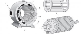
A three-phase generator simply consists of a rotor (rotating magnet) and three stator windings, offset from each other by 120° (three phases - hence the name phase, indicating the terminal of the beginning of the winding). The beginnings and ends of the windings of a three-phase generator are usually designated by the letters A, B, C and X, Y, Z. The first letters of the Latin alphabet indicate the beginnings of the windings, and the last letters indicate the ends. The ends of the windings are connected in a star into one node, called the neutral or zero point. The same principle applies to a step-down distribution transformer - the ends of the windings are connected at the zero point, and the beginnings of the windings are three phases with a linear voltage of 380 Volts.
The generator rotor, rotating, creates an electromotive force, which, provided that the circuit is closed, causes free electrons in the wires to move directionally from a zone with a high potential (an excess of electrons) to a zone with a lower potential (a lack of electrons). Let's conditionally stop time and consider what happens to the voltages in each phase. We know that the voltage in the socket between phase and zero is 220 Volts. This is the effective voltage value, and after converting to amplitude, we get 312 Volts. Let's assume that this is the voltage at terminal A of the generator (or transformer). To determine the voltage on the two remaining terminals, we also conventionally assume that the consumption in the three phases is symmetrical. Then the neutral wire is actually not needed, so we disconnect it from the generator (transformer) - in life this situation is called a break (burnout) of the common zero. But we still have zero. It is important to understand that zero is not just the fourth wire from the transformer. Zero is primarily the common connection point of three phase loads. And current ideally does not flow from phase to zero of the transformer and back. Current flows between three phases if the loads are symmetrical. And only when the loads are asymmetrical (and in real life this is always the case) only part of the current through the fourth wire returns to the transformer.
Assuming that our load is symmetrical, and zero is the connection point of the transformer windings after the loads, we can now find the voltages at the remaining phase terminals and understand the essence of alternating voltage. Since current flows, more precisely, the movement of free electrons occurs between three phases, then if the voltage at terminal A is 312 Volts (take it with a “+” sign, the voltage at the terminal is the potential difference between the beginning and end of the winding (zero point)), then the remaining two terminals B and C should be (it is) -156 Volts. That is, electrons in the circuit begin to move from an area with a potential of +312 Volts to areas with a potential of -156 Volts. If you remember, we stopped time and looked at a specific moment. Let's turn off the time stop. Now the rotor is spinning and the voltage values at the terminals change in a sinusoidal manner. The electrons still move between the phases, but periodically change directions. Concluding a brief excursion into alternating current, I would like to note that when talking about the movement of electrons, we need to understand not the passage of huge distances at the speed of light, but rather millimeters (centimeters). Electrons are slow and do not travel at the speed of light in wires. Propagation at the speed of light occurs only in the electric field, which interacts with all free electrons on any section of the wire.
It will be interesting➡ Chip NE555: Connection circuit and characteristics
The voltage to ground is greater than the phase voltage. That's how it should be
A private house. I made grounding - 15m 10ka reinforcement + 2m strip in the ground, the rest is on the surface. Zero-phase voltage 216 Ground-phase voltage 222 V, i.e. more. Is this normal? If the value is ground-zero, the tester shows 3 V.
The quality of grounding is determined by resistance.
Well, in general, at zero the potential is usually different from zero)) But this is not normal. Re-ground the zero on the input support - and then the zero will be zero
It’s as if we have a network with a grounded neutral by default. So feel free to land before entering the house
——————Long live temporary difficulties!
If the author is very concerned about distortions and really wants symmetry, you can put an isolation transformer at the input (I can’t imagine the price) and make your own power supply system, preferably with a zero, separate from grounding.
Actually there are problems with the RCD
Did I understand correctly that if I connect zero to ground after the meter, then these 3 V will drive the meter around the clock? Or slow down?
------Guys let's be friends! (With)
The old counter most likely will not react to this. But the new electronic one will most likely count.
I also opened a similar topic. I decided not to do the ground. I limited myself to the RCD. Everything works.
Yes, I’m not going to do this, if only because of the 3 V on the body of any device. Another question: the RCD doesn’t care which side goes into the network, which side goes to the meter? Zero is marked there as zero and the phase is marked as 1 and 2.
------Guys let's be friends! (With)
By the way, if one wire from an electrical device is to a grounded pin, and the second is to a phase, it will work due to Chubais.
------temporary difficulties
The phase will still flow through the meter. At least to zero or into the ground. And such unfortunate economists need to be grounded alive! How many times, while working in apartment buildings, did I receive heating and plumbing problems?
------Guys let's be friends! (With)
not in the case of a detached house.
------temporary difficulties
I won’t say about today, but two years ago it worked with a new meter. Province, sir..
------temporary difficulties
even 2 years ago - you surprised me very much - well, you have to look at what province...
So as not to create more topics, can an RCD be installed on an unstabilized line? There are differences from 180 to 230.
In theory, it’s possible. It doesn’t monitor the voltage, but monitors its differences. those. if an equal amount of energy passes through zero and phase, it does not operate. In the event of a leak, a breakdown to the ground, and the like, the balance is disrupted and the circuit breaker is triggered.
Won't it knock out all the time?
Your situation regarding voltage drops is purely rural, maybe one of your comrades can tell you. Uzo is a capricious thing - it leaks a little and gets knocked out - the wiring must be of good quality. For me it works spontaneously 2-3 times a year, I don’t know the reasons, I just turn it on and that’s it.
I'm asking about the dacha)
In my village, differences of 180-230 ouzo works normally, it clearly triggers only for leaks, there haven’t been any false ones in a year.
I spoke with two electricians - both said that it would knock out, but with my head I understand that this should not happen, because it was absolutely rightly noted:
Yes, it’s clear which is better! Nobody argues. Will there be constant alarms on the dacha line? Otherwise, it will simply torture you and you will have to throw it away - money down the drain!
If I may. My machine guns are all Legrandovsky ones. Line 3-phase.
We started from the “dirty” zero, reached the RCD... What is the connection? Three volts at zero relative to the ground is simply nothing for rural areas. My neutral wire is re-grounded to the reinforcement of the reinforced concrete support from which the entry into the house is made. The three-phase RCD tripped only once in four years, during a thunderstorm. Personally, for me, it is better to allow false alarms than one accident.
The stepsons are reinforced concrete, the poles are already rotten, the transformer is dying.
How is the amperage of ouzo selected? Is 25 not enough?
I have a dedicated 5 kW, respectively, the input circuit breaker is 25 A, the ouzo must switch the same current.
And I have a 40 A automatic machine...
It's better to change the IEC to something more decent, IMHO.
Chinese crap.
Grounding through low resistance resistors
The use of low-resistance resistors is considered an ideal solution in terms of the safety of people in distribution networks, as well as in maintaining the insulation of cable lines. The implementation of protection involves connecting the zero point to specialized equipment, which has lower ohmic resistance and gives a signal to disconnect the line. The feeder turns off with a minimum time delay, which is one of the advantages. Others include:
- The first is the neutral, which, when “ground” appears, accurately determines the damaged direction and turns off the required line.
- Second: there is no need for additional calculations and compilation of regime maps with limited possibilities for looping distribution networks.
Important disadvantages of this type of grounding:
- It is not effective for high ground fault currents, as problems arise at substations where low-resistance resistors are installed.
- Low efficiency on overhead lines, as well as on long lines. In the first case, the slightest approach of tree branches will cause the feeder to turn off. This is especially true with consumers of 1 special, 1 and 2 categories.
- Unnecessary shutdowns that occur due to incorrect operation of protections (lack of automatic reclosure) involve downtime in consumption and material losses for the energy supply organization.
Phase in electricity
Do you know, at power plants? Everywhere the principle of its occurrence is the same: the rotation of the magnet inside the coil leads to the appearance of this effect, which is called EMF, or electromotive force of induction. The rotating magnet is called the rotor, and the coils attached around it are called the stator.
Alternating voltage is obtained from constant voltage when the latter is bent along a sine line, as a result of which either a positive or a negative value is achieved.
So, the magnet comes into motion, for example, due to the flow of water. As the rotor rotates, it changes all the time. Therefore, alternating voltage is created. With three coils installed, each of them has a separate electrical circuit, and inside it the same variable value appears, where the voltage phase is shifted around the circumference by one hundred and twenty degrees, that is, by a third relative to the one located nearby.
What are the dangers of a broken phase or neutral wire?
Over time, wire breaks can be observed in sockets, adapter boxes, and switches. This can happen due to a poor-quality connection when the load was greater than permissible. When zero or a phase in an apartment disappears, electrical devices and instruments stop working.
Determining the phase on the apartment site
The same situation will inform the consumer if a wire breaks in one of the power sections to the input or distribution board, then not only one, but all apartments powered by the broken phase will be left without electricity, but other consumers powered by others phases, will receive it. When zero breaks, all apartments in the house are de-energized.
Determination of phase and zero in a room
A home tool for determining the phase is an indicator screwdriver, which in its device has:
- a conductive tip shaped like a screwdriver, which is inserted into one of the holes in the socket to find the phase;
- current limiting resistor;
- LED or neon light bulb, the purpose of which is to show that when they are lit this is a phase;
- on the other side of the probe there is a metal contact for the finger of the hand, which creates a circuit for the flow of safe current.
Current phase determination
When there is a glow of the LED in the contact being tested, then this is a phase. This means the second contact is zero. You can also use a tester or other voltage measuring device to determine when the protective conductor is connected. In this case, 220 V will be displayed between the phase and the working zero, and the arrow will not deviate between the protection and zero.
troubleshooting
The functionality of the apartment's power supply circuit is illustrated by a simple definition. The presence of a phase or working zero is not entirely the correct approach, since in addition to this, a number of other measures must be taken - take into account the position of the switching devices, the presence in the sockets of consumers with heating elements, but turned off by a button on the device.
Finding electricity
For this reason, the search for a network break should be carried out with empty sockets and switched off switching devices (switches), except in cases where the break may be on the line from the switch to the lamp. A typical power distribution scheme in an apartment is when a phase and a working zero are supplied to the sockets, and a phase is supplied to the lighting fixture through a switch. Zero to the lamp is usually supplied directly from the distribution box, which is shown in the photo below:
Why is zeroing necessary?
Humanity actively uses electricity; phase and zero are the most important concepts that need to be known and distinguished. As we have already found out, in phase electricity is supplied to the consumer, zero removes the current in the opposite direction. It is necessary to distinguish between neutral working (N) and neutral protective (PE) conductors. The first is necessary to equalize the phase voltage, the second is used for protective grounding.
Electrical networks with an isolated neutral do not have a neutral working conductor. They use a neutral ground wire. In TN electrical systems, the working and protective neutral conductors are combined throughout the entire circuit and are marked PEN. Combining the working and protective zero is possible only up to the switchgear. From it to the end consumer there are already two zeros - PE and N. The combination of neutral conductors is prohibited for safety reasons, since in the event of a short circuit the phase will be closed to neutral, and all electrical appliances will be under phase voltage.
Marking of wires in a single-phase 220 V network
Considering this type of network, two variations can be distinguished. The first consists of two cores, the second - of three. As you can understand, the main difference between them is the presence or absence of a grounding conductor (PE).
Two-wire wiring is an outdated type and is becoming less common. This design is permitted by GOST and is suitable for premises with low safety requirements. The two-wire TN-C wiring used in older homes had a combined neutral and ground (PEN). Taking into account modern requirements, such a scheme is considered unsafe.
How and with what colors are the wires marked in two-wire single-phase wiring? Let's consider several options:
| (L) | (N) | If you use a solid wire with a brown and blue core, then the first should go to the phase, and the second to the neutral working conductor. This order should not be changed. The only exception is that black, red, gray, purple, pink, white, orange, and turquoise can be used to mark the phase conductor. To be on the safe side, it is recommended to mark the corresponding cores at both ends with tags labeled L (phase) and N (zero). |
| (L) | (PEN) | This circuit has a traditional brown conductor as a phase conductor (L). As in the previous case, the brown coating can be replaced with one of the acceptable colors. The three-color (yellow, green, blue) conductor (PEN) is used simultaneously as a zero working (N) and a zero protective (PE). Despite the combination of N and PE, in fact, the end user does not have grounding. |
Starting from the seventh edition of the PUE (electrical installation rules), electrical wiring in an apartment or house must be carried out with a three-core cable with copper conductors (three-wire circuit).
Let's look at which conductors are included in a three-wire circuit and how they are marked:
| Phase L (from English Live - live) is a working wire under high voltage. | The main color of the core is brown (possibly a brown stripe on a white background) |
| Acceptable core color: black, red, gray, purple, pink, white, orange, turquoise. | |
| Neutral (working zero) N (from English Neutral) is a voltage-free auxiliary conductor through which load current flows in operating condition. | The main color of the core is blue, light blue (possibly a blue stripe on a white background) |
| Earth (protective zero) PE (from English Protective Earth - protective earth) is a separate unloaded conductor for grounding. Under normal conditions, no current flows through the protective zero. | The main color of the core is yellow and green stripes (possibly a green stripe on a yellow background). |
Conclusions Grounding rules
Radical methods for solving grounding problems:
- Only use I/O modules with galvanic isolation
- Do not use long wires from analog sensors
- Place input modules in close proximity to the sensor and transmit the signal digitally
- Use sensors with digital interface
- In open areas and over long distances, use optical cable instead of copper
- Use only differential (not single) inputs on analog input modules
More tips:
- Use a separate copper busbar ground within your automation system, connecting it to the building's protective earth busbar at only one point
- Connect the analog, digital and power ground of the system at only one point. If this is not possible, use a copper busbar with a large cross-sectional area to reduce the resistance between different ground connection points
- Make sure that when installing the grounding system, a closed loop is not accidentally formed.
- If possible, avoid using ground as a voltage reference level when transmitting a signal.
- If the ground wire cannot be short, or if for design reasons it is necessary to ground two parts of a galvanically coupled system at different points, then these systems must be separated using galvanic isolation
- Galvanically isolated circuits must be grounded to avoid the accumulation of static charges.
- Experiment and use instruments to assess the quality of grounding. Mistakes made are not immediately visible
- Try to identify the source and receiver of the interference, then draw the equivalent circuit diagram of the interference transmission circuit, taking into account parasitic capacitances and inductances
- Try to identify the most powerful interference and protect yourself from it first
- Circuits with significantly different power should be grounded in groups, in each group - blocks with approximately equal power
- Grounding conductors with high current must be routed separately from sensitive conductors with low measuring signal
- The ground wire should be as straight and short as possible
- Do not make the signal receiver bandwidth wider than necessary for reasons of measurement accuracy
- Use shielded cables, ground the shield at one point on the signal source side at frequencies below 1 MHz and at several points at higher frequencies
- For particularly sensitive measurements, use a floating battery power supply
- The dirtiest ground comes from the AC power supply. Do not connect it to analog ground.
- Screens must be insulated to prevent the appearance of random closed circuits, as well as electrical contact between the screen and ground
How phase wires are painted
When working with wiring, phase wires pose the greatest danger.
Touching the phase, under certain circumstances, can become lethal, which is probably why bright colors were chosen for them. In general, the colors of electrical wires allow you to quickly determine which of a bunch of wires are the most dangerous and work with them very carefully. Coloring of phase wires
Most often, phase conductors are red or black, but other colors are also found: brown, lilac, orange, pink, purple, white, gray. Phases can be painted in all these colors. It will be easier to deal with them if you exclude the neutral wire and ground.
In the diagrams, phase wires are designated by the Latin (English) letter L. If there are several phases, a numerical designation is added to the letter: L1, L2, L3 for a three-phase 380 V network. In another version, the first phase is designated by the letter A, the second by B, and the third by C .
Ground wire color
By modern standards, the ground conductor is yellow-green. It usually looks like yellow insulation with one or two longitudinal bright green stripes. But there are also transverse yellow-green stripes in color.
Grounding may be this color
In some cases, the cable may only have yellow or bright green conductors. In this case, the “earth” has exactly this color. It is displayed in the same colors on diagrams - most often bright green, but it can also be yellow. Signed on circuit diagrams or on ground equipment in Latin (English) letters PE. The contacts to which the “ground” wire must be connected are also marked.
Sometimes professionals call the grounding wire “neutral protective”, but do not be confused. This is an earthen one, and it is protective because it reduces the risk of electric shock.
What color is the neutral wire?
Zero or neutral is blue or light blue, sometimes blue with a white stripe. Other colors are not used in electrical engineering to indicate zero. It will be like this in any cable: three-core, five-core or with a large number of conductors.
What color is the neutral wire? Blue or cyan
“Zero” is usually drawn in blue on diagrams and signed with the Latin letter N. Experts call it a working zero, since, unlike grounding, it participates in the formation of the power supply circuit. When reading a diagram, it is often defined as "minus", while the phase is considered "plus".
How to check the correctness of marking and wiring
Wire colors in electrical engineering are designed to speed up the identification of conductors, but relying only on colors is dangerous - they could be connected incorrectly. Therefore, before starting work, you should make sure that you have correctly identified their affiliation.
Take a multimeter and/or an indicator screwdriver. It’s easy to work with a screwdriver: when you touch a phase, the LED built into the housing lights up. So it will be easy to identify phase conductors. If the cable is two-wire, there are no problems - the second conductor is zero. But if the wire is three-wire, you will need a multimeter or tester - with their help we will determine which of the remaining two is phase and which is zero.
Determining the phase wire using an indicator screwdriver
We set the switch on the device so that the selected jackal is more than 220 V. Then we take two probes, hold them by the plastic handles, carefully touch the metal rod of one probe to the found phase wire, the second to the supposed zero. The screen should display 220 V or the current voltage. In fact, it may be significantly lower - this is our reality.
If 220 V or a little more is displayed, this is zero, and the other wire is presumably “ground”. If the value is less, we continue checking. With one probe we again touch the phase, with the second - to the intended grounding. If the instrument readings are lower than during the first measurement, there is “ground” in front of you and it should be green. If the readings turn out to be higher, it means that somewhere there was a mistake with “zero” in front of you. In such a situation, there are two options: look for exactly where the wires were connected incorrectly (preferable) or simply move on, remembering or noting the existing position.
And, in conclusion, let me give you some advice: when laying wiring and connecting wires, always connect conductors of the same color, do not confuse them. This can lead to disastrous results - at best, equipment failure, but there may also be injuries and fires.
Methods for determining phase and neutral wires
It is not difficult to find out which core is receiving voltage and which is not. There are several ways to determine phase and zero.
First way. The phases are determined by the color of the core shell . Typically, the working phases are black, brown or gray, and the zero is light blue. If additional grounding is installed, then its core is green.
In this case, no additional devices are used to determine the phases. Consequently, this method is not very reliable, because when installing the wiring, electricians may not comply with the color coding of the cores.
The main difference between phase and linear voltage in AC networks is the voltage value, which for linear is 3 times higher than for phase.
To organize street lighting, photo relays are used. You can find out how to properly connect such a device here.
It is more reliable to determine phases using an electric indicator screwdriver . It is a non-conducting housing in which an indicator and a resistor are built-in. A neon light bulb is used as an indicator. When the tip of a screwdriver touches a bare, live wire, the indicator, if the wire is working, lights up. If it's zero, it doesn't work. Using such a screwdriver, you can determine the health of the network. If, when the tip touches one wire at a time, the light does not light up, then the network is faulty.
It happens that the indicator lights up when you touch both conductors of the wire, that is, both the phase and the neutral. This means that there is a break somewhere in the empty phase. It needs to be found and eliminated.
You can determine the phase with a multimeter . First we set the measurement mode – alternating voltage. Then we hold the end of one probe in our hand. We touch the core with the second probe. If the phase is working, the voltage value will be shown on the device screen.
You can determine the working phase using an ordinary light bulb . We take a light bulb. screwed into the socket, with two pieces of wire. We ground one end. You can ground it by screwing it to the heating battery. The ends of the wires, of course, should be bare. We touch the core with the other end. If the light comes on, then the phase is working.
Construction of household electrical networks
Before embarking on such a responsible operation as identifying a phase wire, it is necessary to understand very well the structure of the household electrical network.
Unlike the networks through which electrical energy is transferred from power plants to the transformer, the voltage in a residential building or apartment is only 220 volts, but even this voltage can be dangerous to life and health, and can also cause a fire due to a short circuit.
Therefore, you can work with electricity only if you follow safety regulations.
A household electrical network, as a rule, consists of a three-wire wire:
Let's now look at each in more detail.
What is a "phase"?
A “phase” or phase wire is the conductor that carries electricity into the house from the electricity supplier. It differs from other cable cores in the presence of a voltage of 220 V. But to operate an electrical device or equipment, a phase wire alone is not enough.
Just as a finger-type battery cannot provide electricity to any device connected with only one pole, so a phase wire needs another conductor whose name is “zero”.
What is zero and how to define it?
“Zero” is a conductor that stretches from the power plant generator to consumers, and although there is practically no electric current in it, it is a full participant in the relationship of transmitting electric current through metal wires.
Determining zero is not at all difficult. You can use a multimeter or tester for this purpose. If measurements are carried out using a multimeter, then it is necessary to connect one of the probes to some grounded object, and the other one in turn to the wires, when the device shows a voltage of 2 - 3 V. then the wire to which the probe was connected at the moment is zero .
A metal radiator of a heating system can act as a grounded conductor during the period when it contains liquid under pressure.
What is grounding?
Unlike “phase” and “zero,” grounding, so to speak, is local. Grounding is a conductor that is connected to the ground directly at the location of the house, and serves to prevent electric shock to a person in the event of a breakdown of the insulation of a phase wire on the device body.