Receiving alternating current
Alternating current can be obtained in the simplest generator with a winding of one turn and one two-pole magnet.
In real generators, the winding, of course, has not one, but many turns. A magnetic field is created, as a rule, not by a magnet, but by an electromagnet. The number of its poles can be more than two. In addition, in some versions of generators, magnet 1 is stationary, and winding 2 rotates (Figure 1, a), in others, winding 2 is stationary, magnet 1 rotates (Figure 1, b), which is very important for design and maintenance, but fundamentally completely indifferent. Why? Because to generate an alternating electromotive force (emf), it is only important that the turns of the winding intersect the magnetic lines of force, and this is equally achieved in both cases.
Figure 1. The principle of obtaining alternating current in generators
When the winding (magnet) rotates, it (he) sequentially in time occupies different positions relative to the magnetic field (winding). First, the winding, the plane of which is perpendicular to the magnetic field, is located in the neutral, that is, between the poles, as shown in Figure 2, a. In this case, the conductors seem to slide along the lines of force and e. d.s. does not arise in them. Then one conductor (its red end) approaches the north pole N, and the other (blackened) approaches the south S (Figure 2, b) and, finally, they pass under the poles (Figure 2, c). In this position, the conductors move perpendicular to the lines of force: e. d.s. reaches its greatest value. In conductors located at different poles, e. d.s. are directed differently: in one of them - beyond the plane of the drawing, in the other - towards us. But the conductors forming the turn are connected to each other in such a way that their e.g. d.s. fold up.
Figure 2. Change in e. d.s. within one period
Next, the conductors move away from the poles (Figure 2, d) and again reach the neutral (Figure 2, e): e. d.s. equal to zero.
Continuing its movement, the conductor, which previously passed under the north pole, approaches the south (Figure 2, f); the conductor, which was under the south pole, is approaching the north: direction e. d.s. reverses. Under the poles (Figure 2, g) e. d.s. again reaches its greatest value, but it is negative.
Finally, the conductors move away from the poles (Figure 2, h) and again go to neutral (Figure 2, i): e. d.s. equal to zero. Then, with each revolution, everything is periodically repeated in the same sequence.
Video 1. Producing alternating electric current
Generation and transformation
The principle of generating electricity is simple. If a magnetic field rotates along a stationary set of coils of turns of a conductor or, conversely, a coil rotates around a stationary magnetic field, then due to the phenomenon of electromagnetic induction, a potential difference arises at the ends of the windings. With each change in the angle of rotation resulting from the described circular motion, the output voltage will also change in both magnitude and direction.
The described conditional generator at a constant angular speed of rotation of the shaft produces a sinusoidal AC with a waveform that is no different from that supplied in a household network. Real generators are much more complex, but operate on the same principles of electromagnetic induction.
These same laws help not only in the production of AC, but also in its transmission and distribution. Voltage conversion by power companies cannot be accomplished without electrical machines called transformers.
This is why Tesla's invention was so important to the revolution in electricity transportation.
Any transformer consists of the following elements:
- primary and secondary windings;
- core.
The word “primary” is used for the winding to which the electrical voltage that needs transformation is applied. The induced voltage on the secondary coil is always equal to that applied on the primary, multiplied by the ratio of turns of the secondary to the primary. The transformer allows you to change the voltage step by step.
Sine wave
The curve in Figure 2 - a sinusoid shows that e. d.s. changes continuously, and the number of its instantaneous values during the period is unlimited: there are as many of them as points that can fit on a sinusoid. During the period, instantaneous identical values of e. d.s. There are two signs of the same sign. Over the period e. d.s. 2 times it reaches the largest (maximum, amplitude) values, but once it is a positive value, the other time it is a negative value. In a word, from a sinusoid you can get the most complete picture of changes in sinusoidal e. d.s. (current) over time.
Video 2. Sine wave
How are sinusoids constructed?
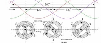
Figure 3 shows how sinusoids are constructed. On the horizontal axis, either time is plotted, increasing from left to right, or the angles of rotation of the winding (magnet), which are counted from a certain position taken as the initial one. The values of e are plotted along the vertical axis. d.s., current or other periodic quantity, proportional to the sines of the rotation angles. Angles can be measured in degrees or radians. In Figure 3, time is given in fractions of a period: T/4, T/2, ¾ T, T; rotation angles are also shown: 0, 30, 60, 90, ..., 360°. It must be borne in mind that in bipolar generators the period corresponds to a full revolution, that is, it is completed through 360°, or 2π radians, that is, in order for one of the winding conductors, leaving under the north (south) pole, to return to it, it must rotate 360°. Therefore, in Figure 3, which is built for a two-pole generator, the period T corresponds to 360°, the half period T/2 to 180°, the quarter period T/4 to 90°, and so on.
Figure 3. Technique for constructing a sine wave
In multi-pole generators, the electrical and geometric degrees do not coincide, because the poles of the same name, for example the north ones, are located closer to each other: in a four-pole generator at a distance of 180°, in a six-pole generator - at a distance of 120°, and so on. And since, regardless of the number of poles, all generators produce current of the same industrial frequency, that is, they have the same periods, the generator rotors must make different paths in the same time: a revolution, half a revolution, a third of a revolution, and so on. Therefore, generator rotors have different rotation speeds, that is, they rotate at different rotation frequencies (speeds): the fastest are two-pole (3000 rpm), four-pole ones make 1500 rpm, six-pole ones 1000 rpm, and so on.
Let us note one extremely important circumstance: the sinusoid is a periodic curve, that is, it has neither end nor beginning, and therefore it is not at all necessary to draw it starting from 0°. With equal success, you can start with 30, 47, 122 (-60°) and so on. But since in these cases the countdown will start later or earlier, it needs to end the same amount later or earlier.
Zeroing in the apartment
This is the connection of the neutral cable with the neutral conductor of the electrical network and the device body. It is assumed that the procedure ensures faster disconnection of the device from the network when touching a dangerous place, if the voltage is above a certain threshold. But it is associated with an additional danger: if there is a zero break, all devices connected at that moment to the apartment’s network will have a phase (and not zero) on the surface, which creates a significant threat to the health of residents. Therefore, such installation work is strictly regulated.
Knowing what exactly is called a phase in an electrical network and how to detect it is extremely important when carrying out electrical installation work. Otherwise, there is a high risk of harming the health of the tenants or the condition of electrical appliances.
Obtaining multiphase currents
If the generator has one or several windings and if they are identical in design, number of turns, wire cross-section, then sinusoids representing the change in e.g. d.s. in each of them are the same. However, they must be placed on the drawing in accordance with both the relative position of the windings and the direction of rotation. Let's explain with examples.
Figure 4. Location of sinusoids in the drawings depending on the direction of rotation of the generator rotor
Figure 4 shows a generator with two windings ax and by, which are placed in the same slots and therefore move equally relative to the magnet. Therefore, sinusoids depicting changes in e. d.s. in both windings are the same. But if the rotation occurs counterclockwise, observing changes in e. d.s. begins at the moment when the windings occupy the position shown in the drawing, and the sinusoids are drawn as in Figure 4, a, then when rotating clockwise, the sinusoids are drawn differently (Figure 4, b). Why? Because in the first case, the conductors pass under the north pole earlier, in the second - earlier under the south.
Figure 5. Shift e. d.s. two windings per quarter period
The generator in Figure 5a also has two windings, but located at right angles. Therefore, they do not pass under the poles simultaneously . This means that the maximum values of e. d.s. they occur at different times and, therefore, the sinusoids must be shifted. It remains to be seen for which part of the period and in which direction. These issues are resolved as follows.
1. Sinusoid e. d.s. one winding, for example ax, is placed arbitrarily in the drawing and through point 0, from which time will be counted in the future, a vertical 1–1 is drawn (Figure 5, b). 2. Determine from Figure 5, a, what position of the conductor corresponds to point 0 and where conductor b is located at this time: is it ahead of conductor a in the direction of rotation or is it behind it. In our case, conductor b is ahead of conductor a. Indeed, the latter is still in neutral, eh. d.s. in it is equal to zero, and the conductor b is already under the pole and its e. d.s. reached its maximum. 3. Determine what sign e has. d.s. in the by winding at point 0, in order to know how to start constructing a sinusoid e. d.s. winding by at point 0 - under the horizontal axis or on it. If the by winding is located in the region of the same pole to which the ax winding approaches during rotation, then the signs of e. d.s. are the same. In our example, e. d.s. winding ax is positive and both windings are in the region of the same pole. Therefore, the sinusoid e. d.s. winding by at point 0 must also be positive. 4. Determine by what part of the period the winding by is shifted relative to the winding ax. This can be seen from Figure 5, a and d, which show two-pole and four-pole generators, respectively. The duration of the period T in any case is determined by the distance between the poles of the same name and the frequency (speed) of rotation. It is easy to see that the distance between the beginnings of the windings, that is, between conductors a and b, is equal to a quarter of the period. 5. It remains to combine the sinusoids e. d.s. Windings ax and by, which is done in Figure 5, d, where the shift between them by a quarter of the period T/4, or 90 electrical degrees, is clearly visible.
A generator with three windings ax, by and cz is shown in Figure 6. The windings are evenly distributed around the circumference, that is, shifted relative to each other by a third of the period T/3 or by 120 el. degrees. With a given arrangement of windings and counterclockwise rotation, e. d.s. winding ax is ahead by T/3 e. d.s. winding by, which in turn is ahead by T/3 e. d.s. windings cz.
Figure 6. Electromotive forces of three windings shifted by a third of a period
Each winding of a generator (transformer, AC motor) is usually called a phase .
Generators with one winding are single-phase, those with two windings are two-phase, those with three are three-phase, and so on. If e. d.s. in different windings reach zero (or maximum) values at different times, then they say that there is a shift , which is determined in fractions of a period or electrical degrees.
How to calculate the cross-section of a stranded wire
How is stranded wire different from solid wire? In principle, nothing, several single-core wires twisted together, and therefore calculate the cross-section of a single-core wire and multiply by the number of wires to obtain the cross-section of a multi-core wire. Let's look at an example: We have at our disposal a stranded wire woven from 12 cores, the diameter of the single-core wire is 0.4 mm. We calculate the cross-section of the core: 0.4 mm x 0.4 mm x 0.785 = 0.1256, round it up and get 0.126 mm 2. Cross-section of a stranded wire 0.126 mm 2 x 12 = 1.5 mm 2. We go into the table and determine that such a wire is capable will withstand a current of 8 Amps.
If desired, you can determine the cross-section of a stranded wire by measuring the total diameter of the cable, since there is space between the conductors, then using a coefficient of 0.91 we will approximately calculate the total cross-section, which will be enough for us with this accuracy. For example, having measured the diameter of a stranded wire, we got 5 mm, we calculate: 5.0 mm x 5.0 mm x 0.785 = 19.625 mm 2, then multiply 19.625 mm 2 by 0.91, we get 17.85 2. From the table we see, that the current for which the wire is designed is more than 63 A.
| Online calculator for determining the cross-section of a stranded wire |
| Enter the diameter of one core, mm: |
| Number of cores in the wire: |
Here is another simple calculation calculator. To calculate the current consumption, we use the well-known formula; to do this, we divide the power of the device (W) by the voltage (volts), after dividing the result is obtained in amperes. The kettle consumes 1200 W from a 220 volt network, calculating 1200 divided by 220 we get a current of 5.45 A.
| Online calculator for determining the current value based on power consumption |
| Power consumption, W: |
| Supply voltage, V: |
To calculate, you must enter both values, otherwise the program will not understand and will display a corresponding message.
Calculation of resistance for connecting LEDs
Sometimes it is necessary to include an LED indicator in the circuit, but the voltage in this area is higher than required. Let us recall that for the lighting of a conventional LED, a voltage of a direct current source of 1.5 - 2 volts is required and the current consumed by it is 10 - 20 mA (for lighting and less within 5 mA), the voltage and current consumption depend on various characteristics, including including the color emitted by the LED and its distinctive characteristics - there is a class of bright LEDs with low current consumption.
The calculation is made using the formula:
ΔU=Uquenching=Upower–ULED, i.e. ΔU is the voltage difference between the power source and the operating voltage value of a given LED. You need to imagine that if you want to turn on the voltage indication, for example 220 volts, then you will need to turn off 218 volts at the resistor, i.e. 220-2=218, this will require a resistor with a nominal value of 15 kOhm and a dissipation power of 3.5 W, in this case it is better to make up three resistors of 5.1 kOhm, or four resistors of 3.9 kOhm (Series E24). Where U is in volts, I is in amperes, R is in ohms.
Phase
It was already indicated above that the windings of generators, transformers and electric motors are called phases. But the word “phase” in electrical engineering is used in several other meanings.
Phases are also called wires of three-phase lines, in contrast to the neutral wire. The phases are designated by the letters A, B, C (a, b, c) or Ж, З, К, since in power plants and substations buses belonging to different phases are painted with yellow, green and red paints. Zero is denoted by the number 0, and sometimes by the letter N (neutral).
A phase in the broad sense of the word is a separate moment in the development of a phenomenon. In periodic processes (which include changes in emf and current), the phase is the value of a quantity that characterizes the state of the oscillatory process at each moment of time.
Thus, the phase can be called both the angle of rotation of the winding (since each angle corresponds to a certain emf value) and the time elapsed from the beginning of the period. The beginning of the period when e. d.s. equal to zero, often called zero phase.
Phase angles that determine the values of e. d.s. or current at the initial moment (from which the consideration of the process of changing emf or current begins), are called initial phases .
It is important to understand that when determining the phase shift between two e. d.s. or currents, it must always be determined between identical phases of the quantities under consideration. For example, the shift α between zero phases (Figure 7, a) and between phases in T/5 (Figure 7, b) is the same.
Figure 7. Determination of the phase shift value
If you need to determine whether one sinusoid is ahead of another or behind it, proceed as follows.
Through the zero phase 01 of one sinusoid (ax), a vertical 1–1 is drawn until it intersects with the second sinusoid (by) (Figure 8, a). If the vertical intersects the sinusoid above the horizontal axis, then the second sinusoid is ahead of the first; if lower, it lags behind . Indeed, the vertical 1–1, drawn through the zero phase of the sinusoid ax, intersects by above the horizontal axis and, therefore, by is ahead of ax. But if by is ahead of ax, then ax is behind by. This can be easily verified by drawing vertical 2–2 (Figure 8, b) through the zero phase by, which intersects the lagging sinusoid ax below the horizontal axis.
Figure 8. Determining the direction of phase shift
Methods for determining phase and neutral wires
Knowing that in electrical engineering, a phase is a wire through which electricity flows to a device, the user may be interested in whether it is possible to find the phase and zero without using devices. There is a way to do this, although it is not particularly reliable, since network installers do not always comply with the standards for color marking of different types of wires. According to standards, the insulation of the neutral cable should be blue or dark blue, and the ground cable should be painted with yellow and green stripes. For phase wires, the color is not regulated; it can be different, but only different from other cables.
You can find the phase by voltage, which is measured with a multimeter. In the settings, indicate an alternating voltage of more than 220 V. Make contact between two probes with the V and COM sockets. The probe located in V touches the wires - when you touch zero, the device will not show anything, but in phase it will detect a voltage of 7-15 V.
You can also use an automatic machine and an indicator screwdriver. 1-2 cm of insulation is removed from the wires. Turn on the machine and bring the screwdriver with the working side to the wire, while keeping your finger on the metal piece next to the handle. When brought to the phase, the light comes on.
Important! With this method, do not touch the working side of the screwdriver with your finger. Before the procedure, the wires must be separated far from each other so that a short circuit does not occur.
The multimeter allows you to detect phase wires
Vectors
In alternating current technology, periodic changes in e. d.s. (currents) are often depicted as vectors, that is, straight segments of a certain length and a certain direction.
To determine instantaneous values, the vector must have a length corresponding to the maximum value of e. d.s. Its initial phase coincides with the direction of the horizontal axis. Then the vector is rotated counterclockwise and projected onto a fixed vertical axis. The lengths of the projections determine the instantaneous values of e. d.s. for each rotation angle, as illustrated in Figure 9. In Figure 9, changes in e. d.s. presented as a sinusoid on which instantaneous e values are marked. d.s. through every eighth of the period, and by projections of the vector onto the axis for the same fractions of the period.
Figure 9. Determination of instantaneous values of e. d.s. when rotating the vector
Vector construction technique
Technique for constructing vectors for two e. d.s. illustrated in Figure 10, a. On the left it shows sinusoids and it is clearly visible that e. d.s. e2 advances e1 by angle α. Right e. d.s. e1 is depicted by the vector E1M, which is located horizontally (that is, so that its projection onto the axis 1–1 is equal to the instantaneous value of e1 at point 0) and the arrow shows the direction of rotation 1. Then the angle α is plotted along this direction and the vector e is constructed. d.s. E2M.
Figure 10. Determining phase shift using a vector
The construction can be done differently. After constructing the vector E1M (which is located horizontally), a horizontal dashed line is drawn through the point of intersection of the sinusoid e2 with the vertical 2–2 (it cuts off the instantaneous emf e2 value corresponding to point 0). Then, with a radius of length E2M, a notch is made from point 0′ as from the center, after which the vector E2M is constructed. With this construction, the angle α is obtained automatically.
Examples of vector diagrams (that is, a set of vectors depicting sinusoidal quantities of the same frequency for different phase angles between e1 and e2) are given in Figure 10, b–f.
Pay special attention to Figure 10, e, which corresponds to Figure 10, d and shows that no matter how the vector diagram is located in the drawing, the phase shift does not change on it and this is very important.
Is it possible to represent the effective (effective) values of e. by vectors? d.s. and currents?
This important question usually causes confusion. You can answer it as follows.
If you need to determine the instantaneous values of a sinusoidal quantity, then it is more convenient to take the vector representing its maximum value, because it is its projection onto the axis that gives the instantaneous values. But in practical activities, they usually deal not with instantaneous values, but with 2 effective values, for example, they say 220 V, meaning by this the effective value and without thinking about the maximum values, which are 41% greater, or about other instantaneous values. Therefore, vector diagrams are usually constructed for effective values. In this case, the phase shift angles between the current, e. d.s., voltage and the like are visible quite clearly, and the results of addition and subtraction of vectors are directly obtained in effective values, which is convenient.
What happens in zero and phase when a wire breaks
What is power factor
If the electrical wire is broken, the corresponding outlet or the device connected to it ceases to function. It does not matter whether the phase or neutral wire is damaged. If the cable between the switchboards of an apartment building and one of its entrances breaks, all apartments connected to the entrance switchboard will lose electricity. If one of the phase wires breaks in a three-phase connection, the current that was in it before appears in the neutral wire, while nothing changes in the two remaining phases.
Method for detecting zero burnout
Adding and subtracting sinusoids
In electrical installations in which several electrical currents operate. d.s., depending on the method of connection, they can either be added or subtracted. The same applies to currents at branching points.
In DC , addition and subtraction are performed algebraically. This means that if one e. d.s. is 5 V, and the other is 18 V, then their sum is 5 + 18 = 23 V, and the difference is 5 – 18 = –13 V. The minus sign indicates a change in the direction of the current in the opposite direction compared to that which would be from only one e. d.s. 5 V.
In AC , addition and subtraction are more complex.
To add two sinusoids e1 and e2 you need to: a) intersect them in several places with verticals 0, 1, 2, 3, 4, 5 ... and so on, at which the sinusoids will cut off the instantaneous values of e. d.s. (Figure 11, a); b) pairwise algebraically add the instantaneous values and the resulting sums, which are the instantaneous values of the total e. d.s., set aside on the same verticals (Figure 11,b); c) connect the vertices of the total instantaneous values with a smooth curve, thus obtaining a total sinusoid from another, for example e1 + e2.
Figure 11. Addition and subtraction of sinusoids
To subtract one sinusoid from another, for example e1 from e2 (Figure 11, a), you need to give the subtracted sinusoid the opposite sign, that is, simply draw its mirror image –e1 (Figure 11, c). Then sinusoids e2 and –e1 are added (Figure 11, d), as described above. In a word, subtraction of sinusoids is based on the well-known rule, which states that subtracting is the same as adding the same thing with the opposite sign.
Period and frequency
If we carefully examine the graph of the flow of periodic alternating current, we can establish the following rule: at the same time intervals of equal duration, oscillatory movements are displayed on the graph with 100% accuracy.
Such time intervals are called periods and are displayed on paper with the symbol “T”.
The frequency of an electric current, which has a variable value, represents a certain number of oscillatory movements repeated within a given unit of time.
To form a unified approach to the designation of electric current parameters, frequency is considered a mathematical quantity equal to the number of periods per second. The unit of measurement is hertz (Hz). AC frequency is one of the most important parameters to characterize the technological process. It is important to understand that numerous electrical machines, devices and alternating current installations can operate effectively only if, when power is supplied to the device, the frequency that corresponds to the technical characteristics and parameters of the device is provided.
The current standard frequency used in AC power is 50 Hz. This means that the electric current will be directed in one direction 50 times within one second and exactly the same amount in the other. The speed of industrial electric generators is synchronized with the economic indicators of the machines, including their weight and overall dimensions.
Addition and subtraction of vectors
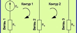
Figure 12, a shows three vectors A, B and C. Figure 12, b shows their addition according to the parallelogram rule, namely: first, the sum of two vectors A and B (B and C, A and C) is found, and then to vector C (A, B) is added to it. Figure 12c shows another way of adding these same vectors in four options. Pay attention to the direction of the sum vector. Comparing Figures 12, b and c, it is easy to see that in any case the same results were obtained.
Figure 12. Addition and subtraction of vectors
To subtract one vector from another, the subtracted vector is rotated 180° (that is, it is given the opposite sign), after which addition is performed according to the parallelogram rule (Figure 12, d). Another way to subtract the same vectors is illustrated in Figure 12, d. Note: the difference vector is directed towards the end of the vector from which the subtraction was made. So, in Figure 12, d, on the left, the difference vector is directed towards the end of vector B.