Varistor (literal translation from English - resistor with variable resistance) is a semiconductor with a nonlinear current-voltage characteristic (volt-ampere).
All electrical appliances are designed for their operating voltage (in houses 220 V or 380 V). If there is a power surge (380V is supplied instead of 220V), the devices may burn out. Then a varistor will come to the rescue.
General information
A varistor is a semiconductor resistor that decreases its resistance as the voltage increases. The conventional graphic symbol (UGO) is presented in Figure 1, which shows the dependence of the resistance of the radio component on the voltage value. In the diagrams it is denoted znr. If there is more than one, then it is designated in the following form: znr1, znr2, etc.
Figure 1 - UGO varistor.
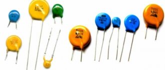
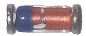
Many beginning radio amateurs confuse a variable resistor and a varistor. The operating principle, main characteristics and parameters of this element differ from a variable resistor. In addition, a common mistake in drawing up electrical circuit diagrams is the incorrect UGO. A varistor looks like a capacitor and is recognized only by its markings.
How to check S14 K275 using this method?
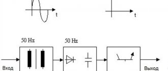
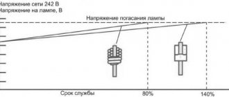
We know that the trigger voltage is 275 volts. When a voltage of 220 volts is supplied, the circuit operates in operating mode: the varistor has infinite resistance, current flows through the main circuit, and the lamp lights up.
We apply increased voltage to the input (for example, 400 volts). The varistor goes into protection mode (the resistance drops sharply, current flows through it), the fuse blows, and the lamp goes out. Conclusion: the varistor is working.
Types and principle of operation
Semiconductor resistors are classified by voltage, since their scope of application depends on this. There are only 2 types:
- High voltage with operating voltage up to 20 kV.
- Low voltage, the voltage of which is in the range from 3 to 200 V.
All of them are used to protect circuits from overloads: the first - to protect electrical networks, electrical machines and installations; the latter serve to protect radio components in low-voltage circuits. The operating principle of varistors is the same and does not depend on its type.
In the initial state it has high resistance, but when the rated voltage value is exceeded, it drops. As a result of this, according to Ohm's law for a section of a circuit, the current value increases as the resistance value decreases. The varistor operates in zener diode mode. When designing a device and for its correct operation, one should take into account the capacitance of the varistor, the value of which is directly proportional to the area and inversely proportional to its thickness.
In order to correctly select an element for protection against overloads in the power supply circuits of a device, you should know the value of the source resistance at the input, as well as the power of the pulses generated during switching. The maximum value of current passed by the varistor determines the duration and repetition period of surges of amplitude voltage values.
Operating principle of varistors
In its normal state, a varistor has a very high resistance (according to various sources, from hundreds of millions of Ohms to billions of Ohms). It passes almost no current through itself. As soon as the voltage exceeds the permissible value, the device loses its resistance thousands, or even millions, of times. After the voltage normalizes, its resistance is restored.
If a varistor is connected in parallel with an electrical appliance, then during a voltage surge the entire load will fall on it, and the devices will remain safe.
The principle of operation of a varistor , if explained in simple terms, boils down to the following. When there is a surge in the electrical network, it acts as a valve, passing through itself an electric current in such a volume as to reduce the potential to the required level. After the voltage has stabilized, this “valve” closes and our electrical circuit continues to operate as normal. This is the purpose of a varistor.
Marking and main parameters
The marking of varistors is different, since each manufacturer of these radio components has the right to install it independently. This is primarily due to its technical characteristics. For example, differences in voltages and required current levels for its operation.
You may be interested in: Selecting and connecting features of an energy meter
Among domestic ones, the most common is K275, and among imported ones - 7n471k, 14d471k, kl472m and ac472m. The most popular is a varistor, the marking of which is CNR (there are also hel, vdr, jvr). In addition, the alphanumeric index 14d471k is attached to it, and this type of designation is deciphered as follows:
- CNR - metal oxide type.
- 14 - device diameter equal to 14 mm.
- D is a disc-shaped radio component.
- 471 is the maximum voltage value for which it is designed.
- K is the permissible deviation of the classification voltage equal to 10%.
There are technical specifications required for application in the circuit. This is because different types of semiconductor resistance must be used to protect different circuit elements.
Their main characteristics:
- Classification voltage is the value of the potential difference, taken into account that a current of 1 mA flows through the varistor.
- The maximum value of the alternating voltage is the rms value at which it opens and, therefore, the value of its resistance decreases.
- The constant maximum voltage value at which the varistor opens in a DC circuit. As a rule, it is greater than the previous parameter for a current of variable amplitude.
- The permissible voltage (limitation voltage) is the value above which the element fails. Indicated for a specific current value.
- The maximum energy absorbed is measured in J (joules). This characteristic shows the amount of pulse energy that a varistor can dissipate and not fail.
- Response time (unit - nanoseconds, ns) - the value required to transition from one state to another, that is, a change in resistance value from a high value to a low value.
- Classification voltage error is a deviation from its nominal value in both directions, which is indicated in % (for imported models: K = 10%, L = 15%, M = 20% and P = 25%).
After describing the operating principle, marking features and main characteristics, the scope of application of varistors should be considered.
What is this element and how does it work?
Varistors are a type of resistors made of semiconductor.
Designation on the diagram
The peculiarity of this element is an abrupt change in resistance at certain voltage values. That is, up to a given value, the resistance of the varistor is kept in a stable state. After exceeding the voltage, the resistance rapidly decreases and tends to zero.
As can be seen in the volt-ampere characteristic graph, the current flowing through the varistor is stable over a given voltage range. As it increases, the current increases sharply. This happens precisely because of the avalanche-like decrease in resistance.
To know how to check a varistor for serviceability with a multimeter, consider its design.
The ceramic layer contains zinc oxide crystals. Depending on their concentration, when a certain voltage is reached at the connecting terminals, the resistance of the ceramic layer and the current flowing through it change.
How a viristor works, a clear example - video
Of course, there is a so-called survivability threshold: the magnitude of the current multiplied by the transit time. When a critical value is reached, the part is thermally destroyed and the circuit will be open . The performance of the varistor depends on this value: that is, the ability to withstand voltage surges.
For example, varistor K275: It can operate in circuits up to 450 volts, and is triggered when the voltage reaches 275 volts. The ability to absorb energy of 151 J allows it to take on a current of 8000 amperes within a few milliseconds. Then the part fails.
Application of devices
Varistors are used to protect electronic devices from surge voltages whose amplitude exceeds the rated power supply. Thanks to the use of a semiconductor resistor in power supplies, it becomes possible to avoid many breakdowns that can damage the electronics. Varistors are also widely used in ballast circuits, which are used in lighting elements.
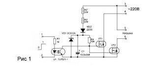
Some voltage and current stabilizers also use specialized semiconductor resistors, and varistor-dischargers with voltages of more than 20 kV are used to stabilize power in power lines. It can also be connected to the wiring diagram (diagram 1), protecting it from overloads and unacceptable amplitude values of current and voltage. When the wiring is overloaded, it heats up, which can lead to a fire.
You might be interested in this: Digital multimeter and multitester measurement
Scheme 1 - Connecting a varistor for a 220V network.
Low-voltage varistors operate in a voltage range from 3 V to 200 V with a current from 0.1 to 1 A. They are used in various equipment and are installed mainly at the input or output of the power source. Their response time is less than 25 ns, however, this value is not enough for some devices and in this case additional protection circuits are used.
However, the technology for their manufacture does not stand still, since it has created a radio element with a response time of less than 0.5 ns. This semiconductor resistor is made using SMD technology. Disc-type designs have a higher response time. Multilayer varistors (CN) are reliable protection against static electricity, which can damage various electronics. An example use is the production of mobile phones that are susceptible to static discharge. This type of varistors are also widely used in the field of computer technology, as well as in highly sensitive equipment.
How to check the performance of a varistor?
We already know that a varistor is essentially a resistance. Therefore, it can be checked with a tester. The simplest way is to measure resistance. It is necessary to remove the part from the circuit and check the resistance in different measurement ranges.
The resistance should be infinitely high - this indicates the serviceability of the varistor. If the circuit does not have additional resistance in the connection circuit, you can check the varistor with a multimeter without desoldering.
For example, in the same extension cord. Just remember to unplug the plug from the socket and turn off all consumers connected to the extension cord.
If it is necessary to accurately measure parameters, it is necessary to assemble a circuit from a not too demanding consumer (for example, a powerful incandescent lamp) and a fuse.
By load we mean the same lamp.
Advantages and disadvantages
To use a varistor, you should become familiar with its positive and negative sides, since the protection of electronics depends on this. The positive qualities include the following:
- High response time.
- Tracking differences using the inertia-free method.
- Wide voltage range: from 12 V to 1.8 kV.
- Long service life.
- Low cost.
A varistor, in addition to its advantages, has serious disadvantages that should be taken into account when developing any device . These include:
- Large capacity.
- Do not dissipate power at maximum voltage.
The capacitance of a semiconductor device ranges from 70 to 3200 pF and therefore significantly affects the performance of the circuit. This value depends on the design and type of device, as well as on the voltage. However, in some cases this disadvantage is an advantage when using it in filters. The value of the larger capacitance limits the voltage value.
At maximum voltage values, varistors-dischargers should be used to dissipate power, since an ordinary semiconductor device will overheat and fail. Every radio amateur should know the algorithm for checking a varistor, since when contacting service centers there is a possibility of paying more for repairs than it actually costs.
How to find a varistor on the board?
According to the diagram above, it is clear that this element is located next to the fuse at the point where the power wires enter the board. This is usually a yellow or dark green disc.
In the photo the varistor is indicated by a red arrow. One might think that the varistor is a blue part covered with black soot, but on magnification you can see cracks on the varistor body, from which the parts located nearby are covered with soot. This can be clearly seen from the reverse side, where the symbols are written. Even if they are not there, you can recognize a varistor, knowing that it is connected in parallel to the load or by the markings on its body.
VA1 is a varistor , and the blue part next to it is capacitor C70.
Do not confuse them, they are the same in shape, so be guided by the markings and symbols on the board.
After you have found a varistor, you need to unsolder it so that a new one can be installed in its place. To solder varistors, I usually use a gas soldering iron, because there is not always power supply at the repair site - at a facility under construction, on a roof, for example. It is also very convenient use a desoldering pump - warm up the soldering area and remove the melted solder with a desoldering pump.
But for these purposes, tweezers or ordinary pliers are quite suitable - you need to grab the leg of the part and pull it out when the solder melts. If your solder does not melt well, then most likely it is high-temperature on the board - the so-called lead-free (you may have noticed on my board the inscription PbF - plumbum free ). In this case, you need to either increase the temperature of the soldering iron tip or drop another lower temperature one on top, the soldering area will melt and the part can be removed. After this, we insert a new varistor and solder it.
For soldering, it is very convenient to use solder in the form of a wire that already has flux inside.
Also note that most boards are double-sided, so you need to solder the legs of the part on both sides of the board, since it often happens that the leg of the part acts as a jumper between tracks on different sides of the board.
After replacing the varistor, all that remains is to install a new fuse and install the board in place.
Typically, air conditioner circuit boards contain varistors for a voltage of 470 V, and fuses rated from 0.5 A to 5 A. Therefore, I recommend that you always have a small supply of these parts with you.
For those who want to see the process more clearly, I am posting a video tutorial:
For those who need to repair the board by replacing the varistor, our service specialists will help, see prices here.