MAGNETOHYDRODYNAMIC GENERATOR DC or AC energy. The movement of such media is described by the equations of magnetic hydrodynamics, which gives the device its name. Direct energy conversion - Ch. a feature of M. g., distinguishing it from electric machine generators that convert mechanical. rotational energy received from the prime mover (usually steam, gas turbines or hydraulic turbines, internal combustion engines, etc.) into electrical energy. The process of generating electricity. current in a magnetic field is based on the phenomenon of electromagnetic induction, that is, on the occurrence of a current in a conductor crossing the magnetic field lines; The difference between a magnetic field is that the conductor in it is the working fluid itself, in which, when moving across the magnetic field strength vector, oppositely directed flows of charge carriers of opposite signs arise.
The working fluid of a gas can be electrically conductive liquids (electrolytes), liquid metals, and plasma. The composition and properties of working fluids have a decisive influence on the type and characteristics of magnetic gases. In the first magnetic fluids, electrolytes and liquid metals were used as the working fluid. Most molecular gases use plasma, in which the charge carriers are mainly free electrons and positive ions deviated by the Lorentz force in a magnetic field from the trajectory along which the gas would move in the absence of a field. In strong magnetic fields, charged particles have time to shift relative to each other between collisions (in a plane perpendicular to the magnetic field); Such a directed displacement of charged particles in the magnetoresistance leads to the appearance of a complement. electric field, so-called Hall field (see Hall effect), directed parallel to the gas flow, and, consequently, the drift of charged particles in crossed electric waves. and magnetic fields.
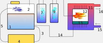
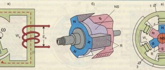
Rice. 1. Scheme of an MHD generator with a linear channel: 1 – source of the working fluid; 2 – nozzle; 3 – MHD channel; 4 – electromagnet; 5 – electrodes; 6 – diffuser; 7 – naked...
M. g. (Fig. 1) consists of a source of thermal energy and a working fluid (can be combined), which is fed at a speed v through an accelerating device (nozzle) into the MHD channel, a magnetic system (electromagnet) to create a magnetic field with induction B, electrodes designed to remove generated electricity. energy into the load, and a diffuser (exhaust section). In the flow of the working fluid (with specific electrical conductivity σ) moving in the MHD channel in the direction perpendicular to the magnetic field lines with induction B, a local emf vB is induced (see Electromotive force), an electric current arises. current in a conductive body and load (electrical network). Power density of M. g. P ≈ 0.25σv2B2 (W/m3).
The MHD channel is the main and technically most complex element and determines the characteristics of the MHD as a whole. Channel designs depend on the type, purpose and operating mode; they must provide, above all, max. work resource and minimum. thermal, hydraulic, electrical losses, etc. The magnetic system is designed to create the maximum possible value of induction and its distribution in the working volume of the channel; it determines the energy, mass and dimensional characteristics of magnetohydrodynamic. generator
For a mechanical generator, in which liquid metal is used as a working fluid, a significant problem in obtaining sufficient efficiency (efficiency) is accelerating the working fluid to high speeds. Large kinetic losses. energy, heat losses and a number of other factors limit the efficiency of such energy. installations up to several percent. Plasma gases have significantly higher performance. To create a plasma of a homogeneous gas, it must be heated to a thermal temperature. ionization (approx. 10000 K); to operate at lower temperatures, vapors of alkali metals (additive) are added (injected) into the gases, which makes it possible to reduce the temperature of the mixture to 2200–3000 K and accelerate the plasma to high speeds (2000–3000 m/s). In contrast to the M.G. with a liquid working fluid, where the generation of electricity occurs only due to the conversion of part of the kinetic or potential energy of the flow at a constant temperature, in M.G. with a gas working fluid three modes are fundamentally possible: with maintaining the temperature ry and a decrease in kinetic. energy; with preservation of kinetic energy and a decrease in temperature; with a decrease in both temperature and kinetic. energy.
Basic M. characteristics are divided into integral, local and specific. These quantities characterize the heterogeneous parameters (energy, electrical, mass-dimensional, etc.) of a particular M. city, both as a whole (integral), and the parameters of the processes in it related to a specific place (local), and its universal indicators (specific), not related to the scale and type of magnetohydrodynamic. generator
Ch. the advantages of a power generator as a powerful device for generating electricity: the absence of moving components or parts directly involved in the conversion of thermal energy into electrical energy (this allows one to significantly increase the initial temperature of the working fluid and, consequently, the efficiency of the power plant); simplicity of the MHD energy conversion cycle, which does not require a complex “steam boiler – steam turbine” unit. M.G. is distinguished from steam or gas turbine plants by quick access to operating mode (low inertia), the ability to be in constant readiness for work for a long time, which is important for peak and emergency power plants, and better environmental friendliness.
Intended effect and origin of the name
The first works in this field are attributed to Faraday, who worked in laboratory conditions back in 1832. He investigated the so-called magnetohydrodynamic effect, or rather, he searched for an electromagnetic driving force and tried to successfully apply it. The current of the River Thames was used as a source of energy. Along with the name of the effect, the installation also received its name - magnetohydrodynamic generator.
You may be interested in:Sandblasting glass: description of glass processing, equipment, application, photo
In this MHD device, there is a direct conversion of one type of energy into another, namely mechanical into electrical. The features of such a process and a description of the principle of its operation as a whole are described in detail in magnetic hydrodynamics. The generator itself was named in honor of this discipline.
You may be interested in: Tram structure: design and main components. Tram control
Conclusions and additional information
Using a gearbox and careful calculation of the blades, you can create a low-speed, low-noise, low-speed generator using neodymium magnets. Modern electronic components and corresponding circuitry will help create an inverter with high efficiency. New battery models perform their functions flawlessly, without routine maintenance, and retain their useful functions after hundreds of recharge cycles.
Wind generators with a vertical axis of rotor rotation
To get acquainted with existing installations, you can see the implemented projects of Sergei Savchenko, Alexander Sedov, Valery Yalovenko, Victor Burlak. Their ideas can be transformed taking into account personal capabilities and preferences. It’s easy to simplify calculations using specialized calculator programs that can be quickly found on the Internet. In any case, the magnetic generator should be considered in conjunction with other parts of the off-grid power supply system to ensure good coordination.
Description of the effect
First of all, you need to understand what happens during the operation of the device. This is the only way to understand the principle of operation of a magnetohydrodynamic generator in action. The effect is based on the appearance of an electric field and, of course, an electric current in the electrolyte. The latter is represented by various media, for example, liquid metal, plasma (gas) or water. From this we can conclude that the operating principle is based on electromagnetic induction, which uses a magnetic field to generate electricity.
It turns out that the conductor must intersect with the field lines. This, in turn, is a prerequisite for flows of ions with charges opposite to the moving particles to begin to appear inside the device. It is also important to note the behavior of the field lines. The magnetic field constructed from them moves inside the conductor itself in the opposite direction from where the ion charges are located.
You may be interested in: The harm of polyvinyl chloride to human health: myth or reality
Advantages and disadvantages
So, what are the advantages of MHD generators:
- This is enormous power with a small installation size (up to several megawatts).
- There is a complete absence of rotating parts, which means there are no friction losses.
- MHD generator – volumetric installation. Why? Firstly, the volumetric processes that occur in the generator reduce the presence of undesirable surface-type processes, for example, reduced pollution, minimum leakage currents, and so on. Secondly, more volume means more power of the machine.
- From the previous it follows that the larger the MHD generator, the higher the efficiency, the less harmful emissions from the installation.
- At one time, a fairly serious indicator of economy and efficiency was achieved when the magnetohydrodynamic unit was connected to the boiler room. The effect was threefold. After burning gas or other energy carrier in the boiler furnace, the exhaust gases (they are ionized) entered the generator, which generated electric current, then the gases entered the steam generator of the thermal power plant, additionally heating water or steam for heating. It should be noted that in those days the efficiency of such a combination was 65%, and this is compared to the traditional efficiency of old boiler houses of 50%.
- And, of course, magnetohydrodynamic generators are mobile installations. And this, as life shows, is sometimes very important.
Definition and history of MHD generator
The installation is a device for converting thermal energy into electrical energy. It fully applies the above effect. At the same time, magnetohydrodynamic generators were at one time considered a rather innovative and breakthrough idea, the construction of the first samples of which occupied the minds of leading scientists of the twentieth century. Soon, funding for such projects dried up for reasons that are not entirely clear. The first experimental installations had already been erected, but their use was abandoned.
The very first designs of magnetodynamic generators were described back in 1907-910, however, they could not be created due to a number of contradictory physical and architectural features. As an example, materials have not yet been created that could function normally at operating temperatures of 2500-3000 degrees Celsius in a gas environment. The Russian model was supposed to appear in a specially built MGDPP in the city of Novomichurinsk, which is located in the Ryazan region in close proximity to the state district power station. The project was discontinued in the early 1990s.
| ARTICLES AND PUBLICATIONS Login or Registration | HELP IN PATENTING | SCIENTIFIC AND TECHNICAL FORUM | Scientific and technical library |
Technology Database Energy converter and storage devices LIQUID MHD - GENERATOR
LIQUID MHD - GENERATOR
(machineless method of direct conversion of thermal energy into electricity)
© Khamzya Umyarov
Contact the author
Modern methods of obtaining electrical energy from fossil fuels are quite complex, since thermal engines require intermediate energy conversion, and such installations are expensive and bulky. Piston internal combustion engines, gas turbines and jet engines are fundamentally simpler than steam power plants, since they do not have an intermediate working fluid - steam, the production of which requires additional equipment (boiler, condenser, pumping equipment, etc.), which is associated with energy costs. However, in these engines, thermal energy is converted into mechanical, and then into electrical. Installations of other types are also complex (hydraulic turbines, nuclear power plants, etc.), so the question of developing new methods for generating electrical energy without intermediate transformations has long been raised. Currently, methods of direct generation of electricity such as thermionic (thermic electron) are of great interest; thermoelectric; magnetohydrodynamic (magnetogasdynamic); electrochemical (fuel cells).
Let us dwell on the magnetohydrodynamic method of direct conversion of thermal energy into electricity. Existing magnetohydrodynamic generators (MHD generators), the basis of which is the working fluid is gas heated to a temperature of several thousand degrees, becoming ionized plasma and a good conductor of electricity (including when adding additives in the form of potassium carbonate or cesium salts), - should be called magnetogasdynamic. But it is possible to develop and create magnetohydrodynamic generators, the basis of which the working fluid is specially prepared liquid solutions. Including gas-liquid dispersions, and based on them - dispersion suspensions. The advantage of the latter is that there is no need to have high-temperature gaseous media, the difficulty of keeping them in closed volumes leads to large heat losses and, as a rule, to a sharp decrease in efficiency up to 40%, while it is theoretically accepted that the method of direct conversion of thermal energy in electrical power it can have an efficiency of 65...70%.
The idea of liquid MHD generators is far from new. Back in 1974, in the book “Technical Thermodynamics” the authors were academicians of the USSR Academy of Sciences Kirillin V.A., Sychev V.V. and Sheindlin A.E. O.
Another important feature that prevents the achievement of theoretically permissible efficiency values is that the MHD generator channel must be in a magnetic field. As is known from electrodynamics, when a conductor crosses the magnetic field lines in this conductor, an electromotive force arises (in particular, in a conventional electric generator, emf in the rotor winding occurs when the conductors of the rotor winding cross the magnetic field lines generated by the stator electromagnet).
The Einstein-de Haas effect is well known, which is widely used in modern high electronic technologies, the essence of which is that when magnetized, a ferromagnet acquires a rotational moment relative to the direction of magnetization (A. Einstein and the Dutch physicist W. de Haas, 1915). Much less known and less widespread is the Barnett effect (1909), the inverse of the Einstein-de Haas effect, the essence of which is that rotation of a ferromagnetic sample increases its magnetization along the axis of rotation.
The Barnett effect in combination with the Merkulov effect (see the material at the link:) can mark the beginning of the development of a new method for directly converting thermal energy into electricity, that is, liquid MHD generators. It is based on low-grade heat (gases with a temperature of no more than 200ªC) and solutions (gas-liquid suspensions) based on compounds, for example, iron. This technology will make it possible to obtain gas-liquid dispersion suspensions, the jets of which, when interacting with the magnetic field of the installation, generate an emf inside the flow, under the influence of which, in turn, an electric current will flow in the closed external circuit of the installation. The advantage of this method of direct conversion of thermal energy into electricity will be the absence of high-temperature media, the difficulty of keeping them in closed volumes does not allow bringing the efficiency of MHD generation to values close to theoretical. In addition, such liquid MHD generators will be cheaper, simpler and more compact compared to magnetogasdynamic ones.
Here it is necessary to refer to the works of Professor of Samara State University, Doctor of Technical Sciences, Head of the ONIL-9 laboratory A.P. Merkulov, who was the first to try to use liquid (water) as a working fluid in the well-known design of the Ranke-Hilsch vortex tube. The results he obtained are interesting in that the water passed through the device was actively saturated with vapor-gas bubbles of various diameters (I repeated this experiment and is completely confirmed). On the stability of the resulting gas-liquid solution A.P. Merkulov says nothing. But at the same time he suggested the mechanism of bubble formation.
Fig.1. Streamlines of swirling fluid flow
In his opinion, in the boundary (near-wall) layer of a swirling fluid flow, shear forces act on the elementary volume of the fluid in such a way that a microvortex formation occurs along an axis parallel to the wall. Under the action of centrifugal forces along the axis, a void appears, which is instantly filled with vapors of the liquid itself and gases contained in the liquid.
Fig.2. Illustration of the Merkulov effect: yellow arrows - flow movement along the wall
In the installation design proposed for consideration, the idea of A.P. Merkulov is supplemented by the fact that elastic mechanical vibrations of low frequency are superimposed on the cylindrical wall washed by the untwisted flow of liquid. That is, the wall performs oscillatory movements, the speeds of which periodically - either coincide with the linear speed of the swirling fluid flow, or are directed in the opposite direction.
Fig.3. The Merkulov effect is supplemented by the imposition of elastic vibrations on the wall
If A.P. Merkulov is right in his assumptions, then in this case almost ideal conditions are created for the generation of a huge number of spinning up elementary volumes of liquid. Approximate calculations show that, for example, an elementary volume of liquid, having a square cross-section with sides of 10 microns, with a calculated amplitude of wall vibrations of 0.3 mm, unwinds and acquires a rotation speed of millions (!) of revolutions per minute. The resulting centrifugal forces acting on the liquid are so great that a spindle-shaped void is certainly formed along the axis of rotation, instantly filled with vapors of the liquid itself and gases contained in the liquid.
Fig.4. The first quarter of the wall oscillation period, when its speed increases from 0 to maximum
Since a sphere has the best optimal ratio between volume and its surface, then, in the end, the spindle-shaped formation takes on a spherical shape, that is, the shape of a bubble. In fact, in the volume of liquid there are inclusions, the characteristic feature of which is that they have their own angular momentum. In quantum mechanics this is called spin. Even if we imagine that it takes several seconds for the torque to completely decay, then even then this time is quite enough for the combination of the Barnett and Merkulov effects to manifest themselves when passing liquid through the magnetic field lines generated by the stator electromagnet. That is, the stator winding will have its own emf.
The source of low-grade thermal energy can be the exhaust gases of internal combustion engines, gas turbines and boilers of numerous heating boiler houses. Indeed, the temperature of their exhaust gases, as a rule, does not exceed 200°C. Meanwhile, when receiving 1 MW of thermal payload from burned natural gas, approximately 1,500 cubic meters of gases are released into the atmosphere. This “waste” heat can be used to generate electricity using liquid MHD generators. If we imagine that the efficiency of such machineless direct conversion of thermal energy into electricity is, for example, 50%, then from the use of 1500 cubic meters. meters of exhaust gases, you can obtain an electrical power of 40...50 kW. But in our time, the capacity of urban heating boiler houses is already measured in hundreds of MW. For example, in Moscow there are a number of district thermal stations (RTS), the capacity of which has exceeded 500 MW.
The Moscow government, in addressing issues of increasing the efficiency of the city's fuel and energy complex, is following the path of accelerated development of so-called cogeneration. That is, gas turbine units (GTUs) are installed on the territory of existing RTS, generating electricity, the heat of the exhaust gases of which is used with the help of waste heat boilers for heating and hot water supply. This provides significant savings in fuel resources.
The author of these lines worked a little at RTS in Moscow Penyagino. The thermal power of the RTS is about 600 MW. In addition to the boilers, two cogeneration gas turbine units are installed there. They are based on two Siemens turbines of 25 MW each. But the direct conversion of heat from almost 850 thousand cubic meters of exhaust gases (per hour) into electricity can provide at least another 30 MW of electrical power.
If the cost of each turbine is $7,000,000, then liquid MHD generators will cost much less.
But the most important thing here is that emissions into the atmosphere can be reduced to zero, which will significantly affect the environmental situation of the metropolis. And the efficiency of using fuel resources will significantly increase. From the “waste” gas-liquid dispersion, a considerable amount of low-potential thermal energy can be selected (see the material at the link: https://moiidei.com/tehnika-tehnologii/utilizator-brosovogo-tepla.html) for heating, for example, feed water. Date of publication:
March 22, 2009
Source:
SciTecLibrary.ru
Back
| about the project | Contacts | Archive of the old site |
| Copyright © SciTecLibrary © 2000-2017 Agency for Scientific and Technical Information Scientific and Technical Library SciTecLibrary. Svid. FS77-20137 dated November 23, 2004. | ||
How the device works
The design and principle of operation of magnetohydrodynamic generators for the most part repeat those of ordinary machine versions. It is based on the effect of electromagnetic induction, which means that a current arises in the conductor. This occurs due to the fact that the latter crosses the magnetic field lines inside the device. However, there is one difference between machine and MHD generators. It lies in the fact that for magnetohydrodynamic options the working fluid itself is used directly as a conductor.
The action is also based on charged particles, which are acted upon by the Lorentz force. The movement of the working fluid occurs across the magnetic field. Due to this, flows of charge carriers appear in exactly opposite directions. At the early stage, MHD generators used predominantly electrically conductive liquids or electrolytes. They were the very working fluid. Modern variations have switched to plasma. Positive ions and free electrons became charge carriers for new machines.
You may be interested in:ATR 72-500 aircraft for short-haul routes
Rotor creation process
The author of the development decided to make the basis of the generator a car hub with brake discs, since it is powerful, reliable and perfectly balanced.
When you start making a windmill with your own hands, you should first prepare the base for the rotor - the hub - and clean it of dirt, paint and grease. Then start gluing the permanent magnets. To create this wind generator, twenty of them were used on a disk. The size of the neodymium magnets was 25x8 millimeters. However, both their number and their size can vary depending on the goals and objectives of the person creating the wind generator with his own hands. However, to obtain one phase it will always be correct to equalize the number of poles to the number of neodymium magnets, and for three phases to maintain the ratio of poles and coils - two to three or three to four. The magnets should be positioned taking into account the alternation of poles, and as accurately as possible, but before you start sticking them, you need to either create a paper template or draw lines dividing the disk into sectors. To avoid mixing up the poles, we make marks on the magnets. The main thing is to fulfill the following requirement: those magnets that stand opposite each other must be turned with different poles, that is, attract each other.
The magnets are glued to the disks using super glue and filled in. You also need to make borders along the edges of the disks and in their center, either by wrapping tape or molding them from plasticine to prevent spreading.
Modification of a car generator
Creating a permanent magnet rotor requires quite a serious intervention in the design. It is necessary to reduce the diameter by the thickness of the magnets plus the thickness of the steel sleeve, which is placed on the rotor to form a continuous magnetic flux and at the same time serves as a landing pad for the magnets. Some experts do without a sleeve, installing magnets directly on the rotor with a reduced diameter and fixing them with epoxy.
The manufacturing process requires the participation of production equipment. The rotor is clamped into the lathe and the layer is carefully removed so that the installed magnets rotate with minimal clearance, but quite freely. The magnets are installed on the rotor plates with alternating polarity.
The greatest effect can be achieved when installing relatively small-sized magnets arranged in rows in the longitudinal direction. A smooth and powerful magnetic flux is achieved, acting on the stator power windings with uniform density at all points.
Making a rotor from a hub and brake disc
The considered method applies to ready-made generators that require minor design changes. Such devices include car generators, which are often used by amateur designers as a basic device. Often, generators are assembled completely independently, without having a ready-made device.
In such cases, they act somewhat differently. The basis is a car hub with a brake disc. It is well-balanced, durable and adapted to certain types of loads. In addition, the size of the hub allows a large number of magnets to be placed around the circumference, allowing three-phase voltage to be obtained.
Magnets with alternating polarity are placed at a distance equidistant from the center. Obviously, the highest number can be set by gluing them as close to the outer edge as possible. The most accurate indicator will be the size of the magnets, which will determine the possibility of placement at a certain distance. The number of magnets must be even so that the rhythm of alternating poles during rotation does not break down.
Gluing magnets to the hub is done using any glue; the best option is epoxy resin, which is used to completely fill the magnets. This protects them from moisture or mechanical stress. Before pouring, it is recommended to make a plasticine rim along the edge of the hub to prevent the epoxy from flowing down from the hub.
The design of the generator on a car hub is most convenient when making a vertical windmill. It is noteworthy that a similar scheme can be used without a hub, on a disk cut from ordinary plywood. This design is much lighter, allows you to choose a convenient size, which makes it possible to create a sensitive and productive device.
Design of MHD generators
The first node of the device is called the channel along which the working fluid moves. Currently, magnetohydrodynamic generators mostly use plasma as the main medium. The next node is a system of magnets that are responsible for creating a magnetic field and electrodes to remove the energy that will be received during the work process. However, the sources may be different. The system can use both electromagnets and permanent magnets.
The gas then conducts an electric current and is heated to a thermal ionization temperature, which is approximately 10 thousand Kelvin. After this, this indicator must certainly be reduced. The temperature level drops to 2.2-2.7 thousand Kelvin due to the fact that special additives with alkali metals are added to the working environment. Otherwise, the plasma is not sufficiently effective, because its electrical conductivity becomes significantly less than that of the same water.
Manufacturing a rotor for a three-phase alternating current generator
The rotor plates are made of organic glass 5 mm thick. Circles with a diameter of 95 mm were cut out of organic glass; according to the markings, 12 holes were drilled in them for neodymium magnets (D – 15 mm). Magnets with opposite poles were glued into the holes intended for them (Appendix sheet V, Fig. 12 - 13). Three such plates were made for the generator. The central plate, which is located between the stator plates, is made only of organic glass. Metal plates made of steel 1.5 mm thick are glued to the upper and lower rotor plates. Each plate contains 12 magnets, oriented along the poles.
Typical device operating cycle
It is best to list other components that make up the design of a magnetohydrodynamic generator along with a description of the functional processes in the sequence in which they occur.
- The combustion chamber receives the fuel loaded into it. Oxidizing agents and various additives are also added.
- The fuel begins to burn, allowing gas to be produced as a combustion product.
- Next, the generator nozzle is activated. Gases pass through it, after which they expand, and their speed increases to the speed of sound.
- The action reaches a chamber that passes a magnetic field through it. There are special electrodes on its walls. This is where the gases enter at this stage of the cycle.
- Then the working fluid, under the influence of charged particles, deviates from its primary trajectory. The new direction is exactly where the electrodes are located.
- The final stage. An electric current is generated between the electrodes. This ends the cycle.
Conclusions and additional information
Using a gearbox and careful calculation of the blades, you can create a low-speed, low-noise, low-speed generator using neodymium magnets. Modern electronic components and corresponding circuitry will help create an inverter with high efficiency. New battery models perform their functions flawlessly, without routine maintenance, and retain their useful functions after hundreds of recharge cycles.
To get acquainted with existing installations, you can see the implemented projects of Sergei Savchenko, Alexander Sedov, Valery Yalovenko, Victor Burlak. Their ideas can be transformed taking into account personal capabilities and preferences. It’s easy to simplify calculations using specialized calculator programs that can be quickly found on the Internet. In any case, the magnetic generator should be considered in conjunction with other parts of the off-grid power supply system to ensure good coordination.
Basic classifications
There are many options for the finished device, but the principle of operation will be virtually the same in any of them. For example, it is possible to run a magnetohydrodynamic generator using solid fuels such as fossil combustion products. Also, vapors of alkali metals and their two-phase mixtures with liquid metals are used as an energy source. Based on the duration of operation, MHD generators are divided into long-term and short-term, and the latter into pulsed and explosive. Heat sources include nuclear reactors, heat exchangers and jet engines.
In addition, there is also a classification based on the type of duty cycle. Here the division occurs into only two main types. Open cycle generators have a working fluid mixed with additives. Combustion products pass through the working chamber, where they are cleaned of impurities in the process and released into the atmosphere. In a closed cycle, the working fluid enters the heat exchanger and only after that enters the generator chamber. Next, the combustion products wait for the compressor, which completes the cycle. After this, the working fluid returns to the first stage in the heat exchanger.
How to make a perpetual motion machine
Homemade generators with neodymium magnets are basically the same type in terms of their operating principle. The standard option is the axial type.
It is based on a car hub with brake discs. Such a base will become reliable and powerful.
When deciding to use it, the hub should be completely disassembled and checked to see if there is enough lubrication, and if necessary, clean off the rust. Then the finished device will be pleasant to paint, and it will take on a “homey”, well-groomed appearance.
Magnets are glued to the rotor discs. The author of the design presented in the photo in the article took twenty pieces measuring 25*8 millimeters. A different number of poles can be used.
In a single-phase device, the number of poles must be equal to the number of magnets. In three-phase, the ratio of two to three or four to three must be observed. Magnets are placed with alternating poles. They must be precisely located. To do this, you can draw a template on paper, cut it out and accurately transfer it to the disk.
To avoid mixing up the poles, make notes with a marker. To do this, magnets are brought on one side: the one that attracts is designated with a “+” sign, and the one that repels is marked with a “-”. Magnets must attract, that is, those located opposite each other must have different poles.
Usually superglue or something similar is used, and after sticking it is filled with more epoxy resin to increase strength, after making “borders” so that it does not leak out.
Main characteristics
If the question of what a magnetohydrodynamic generator produces can be considered fully illuminated, then the main technical parameters of such devices should be presented. The first of these in importance is probably power. It is proportional to the conductivity of the working fluid, as well as the squares of the magnetic field strength and its speed. If the working fluid is a plasma with a temperature of about 2-3 thousand Kelvin, then the conductivity is proportional to it to the 11-13th power and inversely proportional to the square root of the pressure.
Data on flow speed and magnetic field induction should also be provided. The first of these characteristics varies over a fairly wide range, from subsonic speeds to hypersonic speeds up to 1900 meters per second. As for the magnetic field induction, it depends on the design of the magnets. If they are made of steel, then the upper bar will be set at 2 Tesla. For a system that consists of superconducting magnets, this value increases to 6-8 Tesla.
Historical reference
The idea of possibly replacing a solid conductor with a liquid one to generate electricity. energy, was put forward by M. Faraday. However, his attempt to experimentally confirm this idea in 1832 ended in failure, and only in 1851 the English. scientist W. Wollaston practically confirmed Faraday's assumption by measuring the emf induced by tidal currents in the English Channel. Later, various types were proposed and patented. types of MHD energy converters. The first experiments on generating electricity using magnetic gas on nonequilibrium plasma (1938, 1956) and on combustion products (1942) were carried out in the USA. In 1959, the Mark-I electric motor was created in the USA. power 11.5 kW, initial 1960s – supersonic M. G. “Mark-II” using the combustion products of toluene in oxygen with a potassium additive (power up to 200 kW). In 1965, the Faraday M. G. "Mark-V" (power 32 MW) was built, in 1966 - the Hall M. G. "Lorho" (18 MW) of short-term action (minutes). Since that time, work began in many countries on the creation of open-cycle MHD using fuel combustion products for MHD power plants, first in the USSR and the USA, and then in Japan, China, Italy and other countries.
In the USSR, at the High Temperature Institute, since 1961, research has been carried out on the creation of magnetic gas using combustion products of natural fuels for industrial purposes. thermal MHD power plants. In 1965, a model MHD installation U-02 with a linear Faraday channel with a power of up to 0.2 MW was created, which generated electricity. energy 1 month In 1971, an experimental industrial plant was created. installation U-25 with magnets diversified. type; in 1975 electric. The installation power was increased to 20.4 MW, continuous operation time was 250 hours.
In the USA national the program was aimed at creating coal-fired MHD power plants. Basics have been developed and experimentally studied. components of an MHD installation using coal combustion products in oxygen-enriched air. A model installation CFFF (1972) and a demonstration installation CDIF (1980) were created, on which they were mainly tested. technological operating modes and resource characteristics. In 1981, a power plant was created using coal combustion products with a thermal power of 250 MW.
Since 1961, research has begun on the creation of molecular gases using nonequilibrium plasmas for the purpose of their use in stationary energy applications. closed cycle installations. The greatest successes in the creation of stationary molecular gases using nonequilibrium plasma have been achieved in Japan. FUJI-I electrical installations were built. with a capacity of up to 0.7 MW, the FUJI-II project with a capacity of up to 10 MW has been developed.
Since 1965, work began in the USSR on the creation of pulsed (pulse duration 3–10 s) M.G. working bodies. In 1970, a prototype of the self-exciting Pamir-1 MG was created using solid (powder) fuel with a capacity of approx. 10 MW. Subsequently, pilot production was established and, using the block principle, a series of such M.G. with a power of 10 to 600 MW was manufactured, which were used as autonomous powerful current sources. In the USA, similar work, but on a smaller scale, has been carried out since 1968: pulsed MGs using powder fuel with decomp. types of channels with a capacity of several. MW. In 1984, a mobile pulsed (pulse duration up to 30 s) M.G. with a power of up to 5 MW was built in the USA.
Since 1963, in the USSR and the USA, magnetic generators operating on explosive detonation products with decomposition channels have been studied. shapes and powers, including with superconducting magnets. In the beginning. 21st century the following parameters of such (explosive) magnetic glands were obtained: pulse duration 0.1–1 ms, pulse power – up to 300 MW, current – hundreds of kA, energy – tens of MJ, magnetic field induction – up to 6.5 Tesla; the basics have been studied experimentally and theoretically. processes, the patterns of their occurrence have been determined, the capabilities and characteristics of M. g. decomposition have been calculated and/or assessed. types and purposes.
Application of MHD generators
We do not see widespread use of such devices today. Nevertheless, it is theoretically possible to build power plants with magnetohydrodynamic generators. There are three valid variations:
Manufacturing the stator of a three-phase alternating current generator
The generator stator is also made of 8 mm thick organic glass plates. In the plates, according to the markings, cavities are milled to accommodate 9 stator winding coils. The coils are wound with insulated copper wire D – 0.35 mm. Each coil holds the number of turns, according to the calculation data given above. The winding coils are glued into the grooves of the stator plates using sealant (Appendix, Fig. 13-15). Winding of all phase coils must be done in the same direction, marking the beginning and end of the winding. The connection of the coils of each phase is made according to the scheme: end - beginning. In total, three phase coils are placed on the stator plates, connected in series (Appendix, Fig. 16). The connection of all phase windings can be made in two ways: star and triangle (Appendix, Fig. 17 - 18). In our case, the connection is made by a star, including all stator plates. Current rectification is carried out by a three-phase rectifier made of semiconductor diodes (N4107) (Appendix, Fig. 18). The entire “sandwich” of the generator is assembled on a base made of organic glass. The stator plates are rigidly attached to the base with metal stands. The rotor plates are movably mounted on a bearing assembly from the disk drive motor. The axis of the bearing assembly passes through the entire generator and fastens the movable rotor plates (Appendix, Fig. 17).
Prospects of devices
The relevance of magnetohydrodynamic generators depends on a number of factors and still unresolved problems. As an example, we can cite the ability of such devices to generate only direct current, which means that to service them it is necessary to design sufficiently powerful and, moreover, economical inverters.
Another visible problem is the lack of necessary materials that could work for a sufficiently long time when the fuel is heated to extreme temperatures. The same applies to the electrodes used in such generators.
Wind generator on neodymium magnets with a power of 5.0 kW
Currently, domestic and foreign companies are increasingly using neodymium magnets in the manufacture of low-speed electric current generators. Thus, Salmabash LLC, Gatchina, Leningrad Region, produces similar permanent magnet generators with a power of 3.0-5.0 kW. The appearance of this device is shown below:
The generator housing and covers are made of steel, later coated with paint and varnish materials. The housing is equipped with special fastenings that allow you to secure the electrical device to the supporting mast. The inner surface is treated with a protective coating that prevents metal corrosion.
The generator stator is made of electrical steel plates.
The stator winding is made of enamel wire, allowing the device to operate for a long time at maximum load.
The generator rotor has 18 poles and is mounted in bearing supports. Neodymium magnets are placed on the rotor rim.
The generator does not require forced cooling, which is carried out naturally.
Technical characteristics of the 5.0 kW generator:
- Rated power – 5.0 kW;
- Rated frequency – 140.0 rpm;
- Operating rotation range – 50.0 – 200.0 rpm;
- Maximum frequency – 300.0 rpm;
- Efficiency – not less than 94.0%;
- Cooling – air;
- Weight – 240.0 kg.
The generator is equipped with a terminal box through which it is connected to the electrical network. The protection class corresponds to GOST 14254 and has a degree of IP 65 (dust-proof design with protection from jets of water).
The design of this generator is shown in the figure below:
where: 1-body, 2-bottom cover, 3-top cover, 4-rotor, 5-neodymium magnets, 6-stator, 7-winding, 8-coupling half, 9-seals, 10,11,12-bearings, 13 - terminal box.
Winding method for windmill stator coil
In order for a do-it-yourself wind generator on neodymium magnets to work with maximum efficiency, the stator coils should be calculated.
However, most craftsmen prefer to do them by eye. For example, a low-speed generator capable of charging a 12 V battery starting from 100 - 150 rpm should have from 1000 to 1200 turns in all coils, equally divided between all coils. An increase in the number of poles leads to an increase in the frequency of the current in the coils, due to which the generator, even at low speeds, produces more power. The coils should be wound with thicker wires if possible in order to reduce the resistance in them. This can be done on a mandrel or on a homemade machine.
In order to figure out what power potential the generator has, spin it with one coil, since, depending on how many neodymium magnets are installed and what their thickness is, this indicator may differ significantly. The measurements are carried out without load at the required number of revolutions. For example, if a generator at 200 rpm provides a voltage of 30 V, having a resistance of 3 ohms, then subtract 12 V (battery supply voltage) from 30 V and the resulting result is 18 divided by 3 (resistance in ohms) we get 6 ( current in amperes), which will go from the wind generator to charge the battery. However, as practice shows, due to losses in the wires and diode bridge, the actual indicator that the magnetic axial generator will produce will be less.
It is better to take magnets for creating a wind generator in the shape of a rectangle, since their field extends along the length, unlike round ones, the field of which is concentrated in the center. Coils are usually wound round, although it is better to make them somewhat elongated, which provides a larger volume of copper in the sector, as well as straighter turns. The hole inside the coils must be equal to or greater than the width of the magnets.
The thickness of the stator should be the same as the magnets. The form for it is usually plywood; for strength, fiberglass is placed under the coils and on top of them, and the whole thing is filled with epoxy resin. In order to prevent the resin from sticking to the mold, the latter is lubricated with any fat or adhesive tape is used. The wires are first brought out and fastened together, the ends of each phase are then connected with a triangle or an asterisk.