Copper ground bus
The copper-based grounding bus refers to conductors with low resistance values.
The standard element is fixed to the body of the electrical panel, and also easily withstands thermal loads and high voltage during a short circuit. One of the most popular options is a grounding copper strip, made using high-quality electrical copper of the “M-1” grade.
Copper grounding bar
The protective element is manufactured in accordance with GOST 434-78, and is characterized by a high level of alloy purity with a solid metal content of 99% or more.
Due to the high quality of the source material, the copper busbar is designed for operation in operating temperatures ranging from minus 55°C to plus 280°C, with a maximum operating voltage of 1000 W.
Established standards regulate the marking of copper grounding bars with mandatory indication of thickness, width and length.
Tire installation option
Copper grounding bars can be used not only indoors, but also outdoors, due to the following performance characteristics:
- high level of thermal conductivity;
- high level of electrical conductivity;
- low resistivity values;
- resistance to corrosive changes.
When installed externally, copper grounding bars provide effective lightning protection, so they are often mounted on lightning rods.
It is very important to install copper ground bars in regions where there is extremely frequent and high lightning activity.
Main types and types of electrical buses
This article will discuss the main types and types of electrical busbars and the documents regulating their production.
An electrical bus is a conductor with low resistance (active and reactive), to which individual electrical circuits (in low-voltage installations and networks) or high-voltage devices (electrical substations, high-voltage switchgear, etc.) can be connected. The use of tires saves installation space, material and labor costs.
Aluminum and copper are usually used as the main material for the manufacture of electrical busbars.
Tire production is regulated by a number of GOSTs and technical conditions:
GOST 15176-89 Pressed tires for electrical purposes made of aluminum and aluminum alloys. Technical conditions. GOST regulates the parameters in accordance with which aluminum tires must be manufactured - thickness, width, length, cross-sectional area, circumference and the corresponding weight per 1 meter for finished tires. The permissible maximum deviations from the specified values, grades of aluminum, requirements for quality, appearance, mechanical and electrical parameters are indicated. Rules for labeling, packaging and acceptance of tires of this type are provided.
GOST 434-78 Rectangular wire and copper bars for electrical purposes. Technical conditions. The standard specifies the nominal dimensions and design cross-sections of copper busbars, grades of copper, electrical resistivity and maximum dimensional deviations. The permissible tire lengths and coil masses are given, as well as possible deviations from these values. There are requirements for the material used to make tires and the appearance of finished products (permissible defects, colors). The rules for packaging, transportation and storage, acceptance and testing are outlined.
GOST 10434-82 Electrical contact connections. Classification. General technical requirements. A classification of contact connections is given according to such parameters as: scope of application, climatic version and categories of placement of electrical devices, design. Requirements for design, electrical and mechanical parameters, reliability and safety are specified depending on the classification. Links are given to a number of related GOSTs.
GOST 8617-81 Pressed profiles from aluminum and aluminum alloys. Technical conditions. A classification of profiles of this type is given (by type, by material condition and type of strength). References are given to GOST standards with nominal dimensions, and the values of maximum deviations are indicated. The technical requirements for grades of aluminum alloys for the manufacture of profiles, mechanical properties, permissible defects, surface quality and appearance of finished products are described. The conditions of transportation and storage, acceptance rules, and test methods are described.
TU 1-5-009-80 Electrical buses made of aluminum alloys.
TU 16.705.002-77. Aluminum rectangular tires. The technical conditions for the manufacture of aluminum busbars with a rectangular cross-section are described. Nominal and permissible dimensions, alloy grades, and electrical characteristics are indicated.
According to the classification, there are several types of tires.
A busbar is a busbar to which distribution busbars and I/O units can be connected.
Power bus (power bus) is a bus that serves to transfer energy inside power units and between elements of powerful converting devices and is characterized by high currents and voltages. The power bus may be a solid non-insulated bus, a solid insulated bus, or a structure consisting of a series of alternating conductive and insulating layers. Solid bare copper busbar is supplied by manufacturers with various types of insulating busbar supports and insulating screens that prevent direct access to the power busbar terminals. These buses are characterized by a high permissible current density and high insulation voltage. Copper and copper alloys, as well as aluminum, are often used as tire materials. According to the method of fastening, power busbars can be vertical, horizontal, isolated, rear/stepped and universal (multi-standard).
The grounding bus is the main part of the grounding system of electrical installations and electrical networks. It is also called the main grounding bus GZSh. The working zero, protective neutral conductors and external grounding wires are connected to the grounding bus. Typically, the GZSh is a copper plate with perforated holes. Although sometimes steel GZSh are also found.
Perforated copper ground bar
Before connecting to the GZSh, the grounding wires must be crimped with a cable lug or connecting sleeve, and then connected to a bolt with a nut (for example M5). The tire is also equipped with support insulators and fasteners.
Grounding bus on support insulators with grounding wires
Busbars for DIN rail mounting - busbars used for mounting on mounting rails in electrical panels or control cabinets. This type of busbar is often made of brass or tinned copper, and the dielectric base, which is used to attach it to mounting rails, is made of polyamide. Busbars on a din rail are neutral busbars that switch neutral wires and grounding wires in switchboards, or distribution busbars. There are also tires for DIN rails in the housing. Such busbars are called distribution busbars in a block or distribution blocks.
Zero bus in an insulator on a DIN rail
Distribution bus in the block
A distribution bus is a bus connected to a busbar and supplies power to an output device. This bus is part of one section of the NKU (low-voltage distribution and control device). One type of distribution busbars are connecting or comb busbars. They are designed for parallel connection of modular circuit breakers, RCDs, differential circuit breakers, contactors, etc. Comb busbars are made of rectangular copper plate and placed in a plastic case.
Comb tire
A special case of distribution busbars are stepped distribution blocks. The blocks consist of stepped insulating supports, with the help of which fastening is carried out, and, as a rule, 4 copper busbars. There are holes on the bars: threaded (M6) for outgoing circuits and without threads for powering the distribution block. The unit can be installed both horizontally (in the area of switching equipment) and vertically (in the cable channel of the cabinet). An insulating screen is attached to the front of the block.
Step distribution block
Scheme of horizontal and vertical installation of the distribution block
The nominal values of tire parameters are indicated in the GOST standards given at the beginning of the article. Therefore, further in the article only the key characteristics of various types of tires will be given.
The production of aluminum tires of the SHAT brand is regulated by TU 16-705 002-77. These tires are made with a rectangular cross-section. The range of changes in the width of the SHAT bus is from 10 to 120 mm, thickness - from 3 to 12 mm, cross-section - from 30 to 1440 mm 2. The resistivity value is not more than 0.0282 μOhm*m. Tires of brands AD0 and AD31 (GOST 11069-79 and GOST 15176-89) are manufactured with a rectangular cross-section with an area from 30 to 25800 mm2. The range of thickness of these tires is from 3 mm to 110 mm, width - from 6 mm to 500 mm. DC resistivity value: AD0 buses - up to 0.029 μOhm*m; AD31 buses - from 0.0325 to 0.0350 μOhm*m (depending on type). The range of continuous permissible currents (determined by the cross-section of the bus) is from 165 A to 2300 A. For the production of tires, aluminum A5, A5E, A6, A7, AD00, AD0 and aluminum alloys AD31 and AD31E are used. To change the properties of the material, the following technologies are used: hardening and natural aging, hardening and artificial aging, incomplete hardening and artificial aging, as well as hot pressing (without heat treatment). The length of aluminum tires depends on the cross-sectional area and should be equal to or a multiple of: from 3 to 6 m for tires with a cross-section of up to 0.8 cm2; from 3 to 8 m - for tires with a cross-section from 0.8 to 1.5 cm2; from 3 to 10 m - for tires with a cross-section of more than 1.5 cm2. Fluctuations in length - no more than 20mm. Aluminum tires are lightweight and low cost.
Copper busbars in accordance with GOST 434-78 are produced in the following grades: ShMM - soft copper busbar, ShMT - hard copper busbar, ShMTV - hard copper busbar made of oxygen-free copper. The minimum and maximum width of copper busbars is 16 mm and 120 mm, thickness is 4 mm and 30 mm, cross-section is 159 mm2 and 1498 mm2. The value of specific electrical resistance is no more than 0.01724 μOhm*m. The range of continuous permissible currents is from 210 to 2950 A (120×10 busbar) and higher with greater thickness, for a flexible copper busbar - from 280 to 2330 A. The mass of the busbars in the coil should be in the range from 35 kg to 150 kg. The length of the busbars according to GOST is from 2 to 6 m. Hard copper busbars, in comparison with soft ones, have lower conductivity and are used where a durable and stationary busbar is required. For the manufacture of soft tires, copper grades M1, M1M, M2 are used. Flexible tires are more common and offer greater strength, durability and better performance. To make tires from oxygen-free copper, special copper alloys that do not contain oxides are used. Copper busbars have the following advantages compared to aluminum busbars: high specific conductivity (1.6 higher than that of aluminum busbars), mechanical strength, thermal conductivity and flexibility, corrosion resistance, butt contacts with other busbars do not oxidize. Due to high oxidation in open air and brittleness, the use of aluminum tires has a number of limitations. They are not used in machines and mechanisms with moving parts or vibrating bodies. Therefore, in cases where increased demands are placed on live parts, copper busbars are used.
Busbars are current-carrying parts of electrical installations, connecting equipment of various types: generators, transformers, synchronous compensators, switches, disconnectors, contactors, etc. The load current determines the cross-section of the busbars, and resistance to short-circuit current is also taken into account.
A bus bridge made of rigid non-insulated busbars is used: at the outputs of generators, at the inputs of main switchgears, in connections of a transformer with a switchgear and switchgear for 6 - 10 kV, a main switchgear and a communication transformer.
Bus bridge from power transformer
Connections from rigid non-insulated busbars with a rectangular or box-shaped cross-section are made in closed switchgear 6 - 10 kV (including busbars), as connections between the main switchgear and the auxiliary transformer, between switchboard cabinets. Box-section busbars are recommended for use at high currents; they provide lower losses and better cooling. Rigid busbars are secured using support insulators. Flexible busbars are used in switchgear systems of 35 kV and above, in connections of block transformers with outdoor switchgear.
Main switchboard with copper busbar
In all types of connections in low-voltage installations and industrial networks, insulated copper busbars (both rigid and flexible) are used for transmission, distribution of electricity and connection of control devices. Structurally, these buses are one or more thin copper plates, sometimes tinned at the ends, covered with an insulating sheath, usually made of PVC or other dielectric with high resistance. These busbars are an alternative to both cables and fixed busbars and can serve as a connection between: main power machine and distribution equipment (contactors, circuit breakers, switches, etc.), transformer terminal and busbar, busbar and electrical cabinet.
Switching by flexible insulated bus of outgoing machines
The use of insulated busbars saves space, since the busbars can be located much closer to each other than in the case of non-insulated busbars. The advantages of insulated busbars are corrosion resistance and ease of installation. Pad mounting holes are punched directly into the contact material, eliminating the need for cable lugs and eliminating the problem of poor contact connections. Flexible insulated copper busbars are in great demand. Their main advantage over rigid ones is easier installation, since there is no need for special tools or cutting the tire if rotation in the plane is needed. The flexible tire easily changes shape depending on installation needs. However, a number of manufacturers produce solid insulated tires, also on request. Fastening of insulated busbars is carried out using a bolt and contact washers. Tightening must be done with a wrench that has a tightening torque limit. The fasteners should not be covered in grease.
Fastening copper insulated busbar
Another type of flexible busbars are copper braided busbars. This bus is woven from copper strips and is very flexible. It is used in places subject to extreme vibration, such as transformer busbar bridges. These buses are also used to connect various equipment to busbars and bus lines. The contact pads of braided tires are available both with and without drilling. Braided tires are also produced, made by a special method - diffusion welding under pressure. Thin-layer materials are welded by passing direct current through them under pressure. Such busbars are also called lamellar expansion joints or flexible lamellar busbars. They have greater current conductivity and less heat generation.
Tire compensators
They are used where compensation for thermal expansion, vibration or seismic resistance is necessary, and also where regular bending occurs in one axis. For example, this could be: flexible current conductors for welding machines, circuit breakers, power buses for induction and resistance furnaces, etc.
Rigid copper busbar is most suitable for cable replacement, used in switchgear, as well as for the manufacture of busbar assemblies and busbars. Manufacturers produce both perforated and smooth tires of various sizes, in accordance with GOST. Busbar manufacturers currently produce a variety of clamps, connectors and busbar holders that facilitate installation and ensure reliable contact. Clamps are designed for connecting rigid and flexible busbars of various types, bimetallic plates - for aluminum and copper busbars.
Tire holders are available in flat, adjustable flat, compact and reinforced, stepped, and universal.
Universal bus holder
Manufacturers offer a wide selection of insulators: support insulators, bushing insulators, ladder type insulators. All of them are used to fix busbars inside cabinets and enclosures. The insulators are fastened with bolts to the mounting housing on one side, and a busbar is attached to them on the other.
Busbar insulator of “ladder” type
Copper and aluminum producers on the Russian market can be counted on one hand, or rather the holdings that unite them. There are a huge number of brands of electrical tires; we counted more than a hundred brands alone (for all types of tires), so we decided to develop this topic and create a separate website entirely dedicated to electrical tires.
In this regard, we invite all participants in the electrical bus market to post information about their products on the new website.
Source: Shinoprovod.RU
Design features
First, let's look at the design of the comb. The product consists of a copper plate placed in plastic insulation that does not support combustion. Special leads extend from this plate, thanks to which the machines in the panel are connected. The number of plates corresponds to the number of poles.
Please note that there are combs with pitches of 18 and 27 mm. The first ones are intended for switching AVs with a width equal to one module. Accordingly, 27 mm is a width of 1.5 modules
Pay attention to this point when choosing a distribution bus for your own conditions!
Based on the number of poles, connecting busbars are divided into single-pole, two-pole, three-pole and four-pole. Each design option has its own purpose. For example, a single-pole comb is used to connect a single-phase circuit breaker, and a four-pole comb, respectively, is used to install three-phase RCDs with 4 poles (three phases and zero).
The number of taps can be from 12 to 60, so the use of combs to connect two electrical machines is not a rational solution. It is advisable to use a distribution bus when assembling large panels.
The taps themselves can be pin (marked pin) or fork (fork). The former are used much more often, because Fork outlets are not suitable for all machines; they require a special clamp.
The last design feature that I would like to talk about is the cross-section of the bends. As a rule, taps are made with a cross-section of 16 mm2, which is quite enough to withstand a current load of 63 A.
Trolley and lighting busbar trunking: scope of application
The lighting type of busbar trunking is often used today in the planning of retail facilities. This line allows you to quickly and economically install lighting around the entire perimeter of the selected object. The busbar looks aesthetically pleasing, which is why such lines are often chosen for lighting shop windows.
The peculiarity of the lighting busbar is that it allows you to quickly install a line to power low-power lighting fixtures.
By the way, another interesting type of busbar is trolley; this closed busbar is used for the transmission and distribution of electricity in mobile systems.
Metals used in tire production
Depending on the purpose and required operating parameters, the following can be used for the manufacture of conductors:
- copper;
- aluminum;
- steel;
- steel-aluminum - a steel core covered with a layer of aluminum wires.
The advantages of aluminum tires include anti-corrosion resistance, excellent electrical conductivity, low weight and reasonable cost. For their manufacture, low-alloy aluminum alloys with a low content of silicon and magnesium are used to improve the ductility and strength of the metal.
Copper buses with a copper content of up to 99% are in no way inferior to aluminum ones, but are less widespread due to their relatively high cost.
Busbar production standards
- GOST 434-78. This is the standard for copper busbars and rectangular wire. It indicates all the regulatory parameters of these products, sets out the requirements for their shape, production materials and much more.
- TU 1-5-009-80. This standard was developed for tires made of aluminum alloys.
- GOST 15176-89. Extruded aluminum tires and aluminum alloy products. Manufacturing methods, product dimensions, their weight, and requirements for component materials are described in detail. GOST also concerns the final tire parameters that must be achieved during production.
- GOST 8617-81. Standard for pressed tires made of aluminum and its alloys. The document contains a classification of products and the magnitude of their deviations. There are requirements for defects, alloy markings, transportation and storage.
- GOST 10434-82. These are contact connections. The document provides their classification. There are also requirements for design features. For completeness, references to additional GOSTs are included.
- TU 16.705.002-77. These are the technical conditions for the production of rectangular aluminum tires. The document indicates the characteristics of finished products and their permissible dimensions.
Zero bus
Zero tire on DIN rail
The connection of grounding and neutral working conductors is carried out using a zero bus. Its design consists of a conductive core and a plastic base, which is mounted on a DIN rail. The core is made of special electrical copper or brass. The design of the conductive element has holes and clamping bolts. Their presence allows for accurate and safe cabling in switchgear units. Models of zero busbars are made in different lengths, which allows you to make the required number of mounting holes in the core. Their main area of application is AC or DC networks designed for operating voltages up to 400V.
Thanks to the use of a zero bus it will be possible to:
- increase the efficiency of the automatic protective devices used;
- create simultaneously several points for connecting loads to the neutral conductor;
- carefully and safely separate neutral and working conductors;
- perform visible grounding using a plastic device with a cover to protect the terminals;
- install a single circuit from the grounding point to each load.
Installation of the zero bus is carried out directly inside the electrical panel or on a metal rail using a bolted connection. There are open and closed installation methods. The first option is provided for electrical cabinets with a closed structure, which prevents unauthorized persons from accessing the internal contents. Closed installation is optimal for networks to which expensive, energy-intensive equipment is connected - machines and mechanisms, power tools, etc.
GZSH. Main Grounding Bus
Introduction
Hello, dear reader of the site Elesant.ru. The topic of today's article is the main grounding bus (GSB) in the electrics of a private house. Purpose of the GZSh, installation, connection features and material for manufacture.
Purpose of the main ground bus (GZSh)
The main grounding bus (GGB) is the most important electrical element of a private home. With a TN-CS power supply system, which is the main one for power supply to the private sector, the necessary separation of the PEN conductor is necessary. And also re-grounding must be done precisely on the main ground bus (GZSh)
In general, on the main ground bus (GZB) with the TN-CS system, all conductors from the protective systems of the house converge. This is a grounding conductor, and conductors from the potential equalization system and a conductor from the arrester (voltage limiter).
Installation of the main grounding bus (GZSh)
The main grounding bus (GZSh) is installed inside the input distribution device (IDU) or separately. When installed separately, the main ground bus (GGB) is installed in a special housing that resembles a small box.
Important! According to the PUE (clause 1.7.119), open installation of a gas shield is possible only in a special room. But even in this case, the installation site of the open gas shield must be protected from accidental contact.
If there are several power supply inputs in the house, then a separate main grounding bus (GZSh) is installed at each input. Also, cables from the potential equalization system are routed separately to each bus.
Connections on the main ground bus (GZSh)
The main purpose, so to speak, of the main grounding bus (GZB) is to separate the PEN conductor of the power cable. The PEN conductor, after cutting, is connected to a pre-installed GZB.
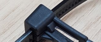
Connection is made using bolts, washers, and nuts. It is advisable to use a locking washer to fix the bolted connection of the main frame (see photo). All connections on the GZSh must be made with bolted fastenings. Each cable connected to the GZSh must have a separate connection.
Note: Bolted connections are needed so that at any time you can disconnect any protective cable separately and make the necessary control measurements (insulation resistance, current flow resistance, etc.)
When installed inside an input distribution device (IDU), the main grounding bus (GGB) is installed directly on the IDU body and has electrically conductive contact with it. (Read in detail about the configuration of the ASU).
A working zero bus (N) is installed next to the main ground bus. The N bus is connected to the main ground bus (GZSh) on which the PEN conductor is separated.
Material for making GZSh
The preferred material for GZSh is copper. It is possible to manufacture the GZSh from steel. It is prohibited to use aluminum tires for main guns. The ban on aluminum for busbars logically leads to a ban on the use of aluminum lugs for electrical cables connected to the main bus.
Design features
Upon closer examination of the design, you will notice that it consists of a conductive core and a base made of plastic, which is designed for installation on a DIN rail.
The photo shows the appearance of the NS:
The current-carrying core contains holes and clamping bolts for fixing the conductors in it, as well as for neat and safe wiring of conductors N inside the switchgear. NS differ from each other in both the installation method (housing) and the number of mounting holes, respectively, in length.
To ensure a high-quality connection, as well as simplify further maintenance, the bus is made of a single conductive element of sufficient size made of electrical copper or brass. With a different number of bolt terminals to which neutral (N) conductors are connected.
A distinction is made between ground buses in a housing and grounding buses without a housing; the externally conductive elements are identical. The neutral bus is made in a housing or an insulator is installed. For the correct functioning of differential protection devices, it is necessary to connect them correctly, and to separate the conductors N from PE in the distribution board. In the case of a metal shield, this can only be done by isolating the neutral conductor from the housing.
PUE safety requirements
The power supply system is ideally compiled according to the circuits recommended by the electrical installation rules (PUE). A power cable is connected to a residential premises or to a separate facility, and its subsequent wiring inside the building is provided using a distribution panel.
For the convenience of such wiring, a zero bus is used. Simply put, such a device is a reinforced open-type conductor in the contact zone. Neutral conductors are connected to it using screw connectors.
A common bus design is a rectangular bar made of durable metal with characteristic conductivity: brass, copper alloys.
Using a common zero bus to connect zero and ground will result in a short circuit. It is worth understanding the difference between splitting and joining by type PE and N.
Installation Rules
Installation of the simplest terminal to the panel is carried out in a closed or open way. The first option prevents malicious damage to the bus of powerful or important devices, the second method is applicable if there is no risk of damage to the device. Zero blocks with screw connections are fixed to the distribution panel on a DIN rail; additional insulation for grounding is not provided.
The cross-section of neutral and phase conductors is the same. A similar requirement applies to tire parameters: the actual cross-section is considered to be the size of the thinnest sections. When combining a group of ground and neutral conductors, end consumers, after dividing the “PEN” input, are connected to different buses: PE and N.
Rationale for use
There is an opinion according to which, when assembling an electrical panel, it is better not to use cable cross-connection modules, since they reduce the useful space in the distribution panel, that is, they clutter it. In addition, the cost of equipment increases.
There is some justice in this statement, especially considering that the overall price of the system will increase, albeit slightly. On the other hand, the use of cross modules provides undoubted advantages; let’s consider them:
- accuracy of installation, to make it clearer, below is a photo showing distribution boards with and without cross-modules. There is no need to designate each of them; the difference is clearly visible.
A clear example: what the use of cross-modules gives.
From the photograph it immediately becomes clear where it will be easier to understand the distribution board diagram or, if necessary, reconnect the lines. So in this case, the aesthetics are quite justified;
- low probability of short circuit; in multi-pole blocks, contact groups are separated by partitions. Please note that despite this, all electrical installation work must be carried out only with the equipment de-energized;
- fastening the wire to the bus ensures reliable contact, which eliminates heating at the connection point;
- a variety of models that allow you to implement connection diagrams of any complexity.
Zero bus: types, what it is needed for
As is known, the power supply system for the end consumer is built according to the schemes recommended by the Electrical Installation Rules (PUE). A power cable is supplied to the facility, and further wiring occurs in the distribution panel.
For ease of installation and organization of power supply lines, inputs with different values are combined into contact groups.
A bus with a phase, a zero bus is a contact block in which there is the ability to reliably connect several conductors to power electrical installations.
Requirements for the zero bus
For a group network, the bus must be a single conductor, without the possibility of switching between its parts. The resistance should be the same along the entire length. Within one group line, it is allowed to combine conductors PE (protective grounding) and N (working zero). Moreover, after dividing the PEN input into PE and N buses, end consumers are connected to different buses. Important! Using one bus to connect the working zero and grounding is prohibited! This is a fundamental issue, it is necessary to understand the difference between separation and combination of PE and N. From the moment of separation, the ground and neutral lines can be laid in the same power cable, but the conductors must be insulated. Regardless of the connection method (three-phase or single-phase), the cross-section of the neutral conductor must correspond to the cross-section of any of the phase conductors. The same requirement applies to the cross-section of the tire itself. The cross-section of the connecting wires from the bus to the final electrical installation cannot be higher than the cross-section of the input power wire. If the bus is a structure with holes for connecting conductors, the actual cross-section is considered to be the geometric parameters in the thinnest part. There are no requirements for the mandatory production of a zero working tire from a specific metal
However, in practice, copper or brass is used. When calculating the cross-section of aluminum busbars in relation to copper busbars, a coefficient of 1.52 is applied.
For convenience, we will consider a single-phase circuit, which is used in most apartments in multi-storey buildings. Two main lines: phase and zero, are always present. They are inserted into the meter (electricity meter), and at the output they become available for further wiring. Depending on the system used, either only a zero bus or a zero and ground bus can be installed.
Purpose
In addition to the GZSh, the grounding system includes a set of copper connecting conductors, as well as a special structure made of metal profiles or fittings, called a grounding loop. The latter is dug into the ground not far from the building to a depth that ensures reliable contact of the metal with the ground.
The main purpose of the grounding bus is to create a special zone at the entrance to the structure that has zero potential with respect to the ground. In addition, the GZSh is intended for connecting parts of electrical equipment operated within the boundaries of a given facility and requiring grounding.
In most cases, the grounding bus collects conductors coming from the following structural elements:
- main ground loop;
- metal casing(s) of various equipment and pipelines;
- lightning strike protection system (lightning rod).
In addition, the so-called “PEN conductor” is connected to the main grounding bus, which is part of the supply voltage cable supply and combines the “working zero” and the protective wire.
On the GZSh strip, the grounding bus is artificially divided into the so-called “zero working” (N) and “zero protective” (PE), each of which has its own fastening and is used for its intended purpose.
Thanks to this separation, it is possible to organize “re-grounding” on the consumer side, eliminating the risk of electric shock if the PEN conductor accidentally breaks.
We also note that grounding according to this scheme is only possible for transformer supply lines with a solidly grounded neutral.
Benefits of using busbar trunking
An electrical bus is more convenient to use than a group of wires
The use of busbars in electrics instead of cable products provides significant savings in material, energy and labor resources:
- Installation takes 2 times less time than cable laying.
- Service life – up to 30 years without the need for complex maintenance.
- The flexible configuration allows for high-quality and safe installation of the network, depending on the route it runs.
- The busbar has a more aesthetic appearance than group wiring.
- Shielding the conductor eliminates the impact of the electromagnetic field on nearby office equipment.
- The design is fireproof and meets safety requirements for IP55 protection level.
Classification of tires by section shape
Depending on the cross-sectional shape of the busbar, there are:
- tubular structures;
- rectangular models;
- box conductors;
- two- or three-way models.
The advantages of rectangular conductors are efficient heat dissipation and low current resistance, which reduces active energy and limits reactive energy. In this way, it is possible to ensure significant savings in expensive energy resources, which is important for large commercial and industrial facilities.
The area of application of rectangular busbars is the installation of networks and distribution devices with current strength in the range of 2000-4000A. It is possible to connect several flat busbars to obtain two- or three-way configurations.
Flat and box modifications of the busbar are used in networks operating under voltage up to 35 kV.
The optimal modification is considered to be a tubular electrical busbar. Its main advantages include effective heat removal, high strength and uniform distribution of the resulting electric field.
More details about the appointment
Using a grounding zero bus in the wiring system allows you to solve many important issues:
- Creation of several points to share the total load from the main input to the neutral conductor.
- “Opening” the grounding mechanism through the use of a transparent cover in the design that protects the terminals.
- Increasing the efficiency and performance of automatic protection devices.
- Ensuring line continuity from direct grounding to the output point.
- Saving space in the panel, since there will be no need to place several single tires.
- Separation of neutral and phase wires.
In general, the zero bus allows you to raise the security of the network to a qualitatively new level, however, its use and connection must be as competent as possible, therefore special requirements are imposed on the installation of this element of the electrical network.
Purpose: what is it for?
The main purpose of using such a device is the convenience of further wiring throughout the room, as well as guaranteeing safety during operation of power conductors.
Area of application: networks with a maximum voltage of 400 volts (DC and AC).
Advantage of using:
- Organization of several areas for connecting loads from the common input to the zero conductor.
- Arrangement of a visible type grounding (device with a transparent cover), which will help cover the terminal block.
- Improvement and rapid connection of several networks (one node allows the input of up to 40 conductors with a 3 mm cross-section).
- An unbroken electrical circuit in place with grounding (also before the load).
- Separation of conductors into protective and working grounding.
Competent and professional separation of electrical wiring in a home or office with many electrical points cannot be ensured without the use of such a simple device.
Characteristics
When choosing the necessary zero buses, it is worth presenting clear requirements for the design. The main thing is the cross-section of the wire. Guided by the clear rule “the cross-section of the wire does not exceed the cross-section of the main grounding bus,” you can provide high-quality power supply and save money on maintenance in the future.
The characteristics of the zero bus vary depending on the type of installation. There are two types of devices according to the distribution scheme that meets the requirements of the PUE:
In the first case, a grounded bus, which is a tightly grounded neutral, in which connection to the protective ground is provided exclusively at this point. Further, only two busbars are inserted into the shield along the insulated conductors. This scheme is considered the safest, since the neutral and grounding buses are separated directly at the entrance of the device into the room.
The second option presents an outdated but popular TN-C type circuit. In this case, the grounding is not represented by a separate conductor, but in the panel itself there is only a zero bus. Here, too, you cannot connect ground and zero. Therefore, here the concept of “earth” in its usual representation is not present.
What is grounding
Grounding
– a method of protecting the user from electric shock when voltage is applied to the device body as a result of an accident. The essence of grounding is to connect the housing of an electrical installation or device to the ground.
Grounding is performed using a grounding device. It consists of a grounding conductor and a grounding electrode. The ground electrode is located directly in the ground. The grounding electrode connects it to any point in the electrical installation or network.
Grounding diagram
In the illustration, the grounding conductor (PE) is connected to the ground and the working zero (N).
There are several grounding systems:
- TN system with the TN-C, TN-S and TN-CS circuits described above. In these systems, the neutral conductor is solidly grounded.
- TT system. Current-conducting parts of electrical installations and the neutral conductor are grounded independently of each other.
- IT system. Conductive parts of electrical installations are grounded, the neutral conductor is not grounded.
In the event of an accident and the supply of electricity to the body, the circuit breakers are triggered due to grounding. If the fuses fail, most of the electricity goes into the ground. This protects a person from electric shock that is dangerous to life and health.
Grounding is used in industry and at home.
Briefly about the design and operating principle
If you look closely at the photo of the zero bus, you can see a conductor made of electrical copper or brass on a plastic base. Each mini busbar is separated from its neighbor by a transparent plate, ensuring safety and insulation.
The holes and clamping bolts in the structure are designed to secure conductors and route them safely, and the device is fixed to a DIN rail using a plastic housing.
The length of the product depends on the number of mounting holes available, however, despite the difference in the clamping bolts, the tire is always monolithic, which simplifies maintenance and increases the safety and reliability of fastenings.
Also, grounding buses differ in the presence of the housing:
Zero tires with a body inside do not differ from their “bare” counterparts, but are externally enclosed in a special plastic block, which in most cases is made of opaque white plastic on three sides, and with a transparent bluish cover on the front side.
It is easy to identify this grounding device in the shield not only by its oblong shape, but also by the obligatory presence on the body or base of a blue or light blue color - a clear indicator of the zero type of the electrical network element.
Secrets and standards of installation
When installing the zero bus, one of several possible types of installation can be used (the appropriate one is prescribed in the instructions):
- On an insulator, screwed in the center or along the edges;
- Screw;
- On DIN rail;
- On G-rail.
In turn, zero bus insulators can be absent or can be case-type, “rack” type, combined, single or double corner (“leg” type).
Installation can also be closed (for example, for powerful or important equipment, to exclude the possibility of malicious damage to the tire) and open (when there is no risk of hacking or damage to the unit).
Below are detailed instructions on how to connect the zero bus, accompanied by step-by-step photographs:
- SIP wires: types, differences from cable, features and advantages
What is a Power Cable?
- How to conveniently unwind a cable coil on site during electrical installation
- Familiarize yourself with the appropriate panel connection diagram, find the zero bus in the image (the icon repeats the general appearance of the device marked “N”).
- De-energize the electrical panel by unscrewing all existing plugs or placing the circuit breakers in the inoperative position.
- Check that there is no voltage by holding an indicator screwdriver or multimeter to the input conductors.
- Determine the location for placing the bus depending on its design features (if fixation to special strips is provided, then install the necessary ones in the panel; if not, fasten them through insulators to a free place).
- Install the strip on the DIN or G using special clamps, or directly into the panel using a screw type of installation from the center or sides (where the insulator is located).
- Check the reliability of the fastenings by trying to “loose” the installed structure.
- Connect the conductor coming from the residual current device to one of the busbar clamping bolts.
- If the circuit has two or more protective connection devices, then each of them is connected in series to the bus.
- Connect the neutral conductors coming from the circuit breakers of each branch of the network to the corresponding terminal of the neutral protective device.
- Connect the common “zero” of the network to the outer terminal on the zero bus.
- Check the correctness and quality of all connections made.
- Turn on the electricity supply.
During work, it is important to follow the safety rules:
- Install only when there is no current in the conductors;
- Use special clamps, terminals, and not homemade “twists”;
- Ensure good contact of the wires, if necessary, trim and strip their ends;
- Do not allow wires to overlap, twist, break or bend;
- Do not neglect marking conductors in any available way (color, signature, signs).
The zero line is an integral part of any electrical network, so it is important to properly organize its functioning inside the panel. The zero bus will provide order and the possibility of sequential connection of all contacts to ensure safe, comfortable and complete use of electricity.
Specifications
The grounding bus must be installed inside the electrical panel and connected to the current grounding circuit.
Due to its basic technical characteristics, such an element is used as a conductor between the grounding system and the plug part of the technical installation. Inside the input devices, as a rule, grounding buses of the “PE” type are used.
Ground bus with ground wires
In such conditions, the grounding conductor must have the appropriate cross-section:
- copper conductors - 1.1 cm or more;
- aluminum conductors - about 1.7 cm or more;
- steel conductors - 7.5 cm or more.
The cross-sectional parameters of the installed grounding bus must correspond to the parameters of the conductor.
| Tire type | Conductor cross-section | Current | Number of holes for fasteners | Number of clamps | Dimensions |
| RE 6/1 | 1.5-16 mm2 | 63 A | 1 | 6 | 6x9x46 mm |
| RE 8/1 | 1.5-16 mm2 | 63 A | 1 | 8 | 6x9x58 mm |
| RE 8/2 | 1.5-16 mm2 | 63 A | 2 | 8 | 6x9x64 mm |
| RE 10/2 | 1.5-16 mm2 | 63 A | 1 | 10 | 6x9x70 mm |
| RE 10/1 | 1.5-16 mm2 | 63 A | 2 | 10 | 6x9x76 mm |
| RE 12/1 | 1.5-16 mm2 | 63 A | 1 | 12 | 6x9x82 mm |
| RE 12/2 | 1.5-16 mm2 | 63 A | 2 | 12 | 6x9x89 mm |
| RE 14/1 | 1.5-16 mm2 | 63 A | 1 | 14 | 6x9x95 mm |
| RE 14/2 | 1.5-16 mm2 | 63 A | 2 | 14 | 6x9x102 mm |
| RE 16/1 | 1.5-16 mm2 | 63 A | 1 | 16 | 6x9x107 mm |
| RE 16/2 | 1.5-16 mm2 | 63 A | 2 | 16 | 6x9x114 mm |
| RE 18/1 | 1.5-16 mm2 | 63 A | 1 | 18 | 6x9x119 mm |
| RE 18/2 | 1.5-16 mm2 | 63 A | 2 | 18 | 6x9x126 mm |
| RE 20/1 | 1.5-16 mm2 | 63 A | 1 | 20 | 6x9x132 mm |
| RE 20/2 | 1.5-16 mm2 | 63 A | 2 | 20 | 6x9x138 mm |
| RE 24/2 | 1.5-16 mm2 | 63 A | 2 | 24 | 6x9x163 mm |
The grounding bus can be of the zero working type “N” and the protective type “PE”, but the installation of such a device must be carried out by specialists, which will make the operation not only durable, but also safe.
Design
Before you figure out how to connect the zero bus, you should take a closer look at the design characteristics of the element being described. The zero bus is presented in the form of a core responsible for conducting current; its base is made of plastic and is used for installation on a DIN strip.
The current-carrying core contains recesses and clamp-type bolts; they are used to fix the bus conductors, and also provide high-quality internal wiring of the distribution device.
The described tires differ from each other in the following elements:
- presence and absence of the body;
- number of installation holes;
- length.
In more detail, the design of the zero tire can be found in the photo.
Installation Rules
Installation of the NS is possible both on a special rail and in an electrical panel. Installation options are available in both closed and open ways. The open method is perfect for a cabinet that will be closed to unauthorized persons. The closed version is used in situations where equipment is used that is connected to very important elements. An example is a power socket for various electrical tools.
The video below clearly shows how to install the NS on a DIN rail and how to fix it more reliably:
So we looked at the structure and purpose of the zero bus. We hope the information was useful and interesting for you!
You probably don't know:
- What is GZSh in electrical engineering?
- Why do you need a cross module?
- What is the danger of a broken neutral wire?
Installation rules
Depending on the selected type of device, installation is carried out using several methods:
- DIN rail mounting. (through insulators or directly into the electrical panel).
- Installation through corner insulators.
- Mounting in electrical panel.
Installation can be carried out in an open or closed way:
- Open is used if there is a closet where access to outsiders will be limited. Installation is carried out with a visible terminal block.
- A closed installation option is used if the equipment is connected to particularly important systems, for example, to a power outlet in electrical installations.
After any installation option (open or closed), there should be no access to the current-carrying conductors, since in the generating installation the zero is solidly grounded, and touching the connection point is deadly. When choosing tires, you should pay attention to the manufacturer and the price of the device. Thus, cheap Chinese tires may simply burst during operation or even at the beginning of installation.
The zero bus is the most important structural element of busbars. It is used to connect ground and zero conductors. This element is used to provide both AC and DC power networks.
It is better to make two zero tires in the shield!
28 Jan 2022 Assembly of shields
Hello everyone, today is an article on practical experience in assembling electrical panels from experienced electrician Sergei Panagushin from Izhevsk. We will talk about such a nuance as installing zero busbars in the shield; Sergey will tell you how best to do it so that the contact of the busbar with the wires is the best.
If it’s not difficult for you, vote for this article by Sergei here - https://vk.com/wall-125051812_548
Just like it.
So, word from Sergei:
Hello dear reader! In today’s article I would like to share a couple of tricks that can be used when installing automatic machines and zero tires in the dashboard.
So: it is best to install tires not one at a time, but two at a time, as shown in the photo.
Why is this being done? Everything is very simple: with such an installation, the contact area increases and the connection is duplicated, and if under one screw the contact loosens, that is, the second contact and such a contact point will not heat up, which reduces the risk of failure of the electrical supply system.
When installing busbars on circuit breakers, the insulated part can be wrapped with insulating tape instead of using end caps. This can be seen in the photo.
You don’t need to wrap a lot of insulating tape, just 1.5-2 turns is enough; if you do more, the busbar will not fit completely into the terminals of the machine, which can also have a detrimental effect on the operation of the electrical supply system. This is done in order to avoid causing an accident if work has to be done on the panel with partially relieved voltage.
PS I also sometimes use insulating tape as a tire heating indicator. For example, in the switchboard, we wrap insulating tape around the bus and periodically, when taking readings in the electrical switchboard, we look at the condition of the insulating tape
If it begins to shrink, then this indicates that there is heating in this place and you need to figure it out... Thank you for your attention!
Video from Sergei Panagushin:
Assembly of a 1-phase shield: Instead of an RCD, a difavtomat. 4 differentials for 4 groups.
Crazy hands: “comb” made of wire:
Crazy hands: Zero tire bulkhead:
The procedure for installing devices in the panel
So, we have discussed all the general points regarding the connections themselves. Now let's see in what order, according to what scheme, the devices are connected into one system in the panel. The following is step-by-step instructions.
Steps, photo Description
Step 1 - DIN Rail Installation All devices require a base on which to mount them. This is a DIN rail, which is screwed onto screws inside the panel. This metal strip is made of steel and can either be included with the shield or be purchased separately. In the second case, most likely, it will have to be cut to length so that it fits inside.
Step 2 - installation of tires At the next stage, tires are put on the rail - zero (blue) and ground (yellow). The rail is shaped in such a way that devices installed on it snap onto its edges.
Now let's talk more about tires. These elements are required in order to connect all the terminals, in particular those going to zero and ground. They are a solid metal base in PVC insulation, with holes of different sizes and screw terminals for fastening wires.
Step 3 - installation of machines Next, machines are attached to the rail
Please note that they are held in place using a small plastic clip that should be facing down. If it is necessary to replace the device, the latch moves away, after which the machine can be freely removed.
Step 4 - zero connections Having installed all the devices on the rail, we begin to power them
Let's say that you have a three-wire wire running into the panel. Each vein will have its own color. The following notations are generally accepted. Blue is zero, yellow or yellow-green is ground, and white or pink is phase.
So, the blue wire is connected to the zero bus, and the yellow wire to the ground bus - everything is logical and simple.
Step 5 - connecting the phase (usually the machine on the left is powered first) The phase, as we said earlier, is connected to the machine from above. We strip the wire of insulation, insert it into the terminal, but do not tighten it right away if you will use jumpers. In general, it is better to install them first, and only then connect the power.
Step 6 - connecting a differential machine If you have a differentiated machine in your circuit, then you will immediately notice that it has two terminals on top. One goes under phase, and the other goes under zero. How not to get confused when connecting?
On the front side of the machine there is a diagram that you need to pay attention to. It will show the inputs with symbols
The first is designated by the letter N - this will be zero. The second is marked with the letter L or the number 1 - this is the phase. Accordingly, we connect the zero bus and output N with a piece of wire, and with the second we throw a jumper from a single-pole circuit breaker onto the phase.
Step 7 - connecting the wires coming from the rooms Next, the machines need to connect all the wires coming out of the house - those that lead to junction boxes, sockets and switches. We also act using color coding of wires. We throw zeros on the zero bus, ground - on the ground bus. The white wire is connected to the lower terminals of the machines, which work like switches - they connect/disconnect the circuit. In the case of differentiated machines, the outputs are connected in the same way as described above. Output N – to the zero bus, the phase is connected to the white wire.
So, we have analyzed the simplest circuit, of course, there are a lot of types of protection devices, but the connection principle is the same, the main thing is not to mix up the wires and not cause a short circuit. The shown circuit is parallel, that is, the devices will work even if one fails or is disconnected.
You definitely shouldn’t do more complex serial connection options yourself. Although if you are interested, you can search for information on the Internet. We also recommend watching our selected videos that will help you understand the topic even better.
We tried to explain everything in popular language. Now you know how to properly connect the machines in the panel; we hope you liked the material and will find it useful in the future.
Installation
There are several ways to organize the installation of a grounding bus, but the most popular are installation in an electrical panel and outside the cabinet.
Panel mounting
Cabinets with an installed bus can be placed on the facade of the household or in a special, separate panel room. For outdoor or outdoor installations, shields are suitable, the body of which is marked with the IP index. Installation of a grounding device involves the following activities:
- fixing the main grounding bus with a bolted connection on the body of the steel shield;
- connecting the protective element to the zero rail using a jumper made of steel or copper;
- The dimensions of the installed element must be comparable to the cross-sectional indicators of the “protection” and “zero” conductors.
Grounding diagram
It should be noted that the rules for placing the grounding bus and other elements inside the electrical panel are not specified in regulatory documents.
The PE copper grounding plate installed inside the shield must have a minimum cross-section of 10 mm2, and the steel one - at least 75 mm2.
Installation outside the panel
External installation of the grounding bar is carried out in areas that have sufficient protection from unauthorized access by unauthorized persons. Fixation is carried out with durable insulators.
Assembly and installation of electrical panels. Cable connection diagram
The most convenient options for external arrangement of the grounding bus include the use of special DIN rails.
A fairly common method used to connect individual elements of the grounding bus is welding, which fully complies with all GOST requirements for arranging reliable and safe contacts.
Purpose of the GZSh
The task of the GZSh is to provide zero protective potential relative to the ground at the entrance to the building or electrical installation. For this purpose, a ground loop is connected to it. Ultimately, electrical equipment housings and third-party conductive parts, which may be exposed to dangerous potential during operation, are connected to the main power supply through cables of outgoing lines or directly. This happens when the insulation inside the conductive shells of panels, control stations, electric motor housings, and lamps is broken. All household electrical appliances with a metal casing may also become energized if internally damaged.
Electrical contact of a person with structures that are energized due to insulation failure is called indirect contact. There is also direct touch, when a person directly touches live parts under voltage.
In electrical installations with a TN grounding system, a protective shutdown will also occur. The current flowing into the ground loop will be sufficient to trip the supply line circuit breaker. If the current exceeds the cutoff operation setting, it will operate; if it is not enough, the machine will turn off due to overload. This process is called protective shutdown.
In CT grounding systems, there may not be enough current for a protective shutdown to occur, since the grounding devices of the substation supplying the facility and its own charger are not electrically connected to each other. Communication is carried out only through the surface of the earth. But at the same time, the life-threatening potential will still be reduced. The only difference is in the method of protective shutdown - for this purpose you will need an RCD that responds not to short-circuit current, but to differential current.
Electrical busbar markings
Marking of zero tires
The application of color markings to electrical busbars is regulated by current standards. Compliance with their requirements is mandatory for every manufacturer. Marking can be applied both at the production stage and after its completion. In the first case, colored insulation is used, in the second, colored insulating tape is used, indicating different phases of the conductor.
The color designation of tires allows you to accurately determine their type and purpose:
- The grounding conductor is marked in yellow and green in the form of alternating longitudinal stripes.
- Neutral and working conductors are indicated using blue color.
- Connecting conductors involves using all three shades in different versions: insulation with longitudinal yellow and green stripes and a blue line at the end, or blue insulation with a yellow-green stripe at the joints and at the ends of the conductor.
According to the requirements of current standards, along with the color marking of conductors for alternating current networks, the following letter designation of conductors is used:
- in a single-phase network – L;
- in a three-phase network - L with numbers from 1 to 3;
- medium – M;
- neutral, or zero – N;
- grounding – PE;
- combined working and neutral - PEN (combination of the designations of each of the conductors used).
Models for DC networks are marked with the letter L with a + or - sign, respectively - a positive or negative conductor.
Colors of wires and buses in DC circuits
DC circuits typically use only two buses, namely plus and minus. But sometimes DC circuits have a middle conductor. According to the PUE, buses and wires are subject to the following markings in DC circuits: positive bus (+) - red, negative (-) - blue, zero operating M (if available) - blue.
How to connect several machines
The choice of circuit is determined by the characteristics of a particular electrical network. The easiest way is to install one RCD immediately after the meter. A safer option is to connect protective devices on individual lines. If one device fails, the others will remain in working order. The implementation of the second scheme requires the use of a marker panel.
Simple scheme
Using an example, it is convenient to consider a single-phase circuit used for most apartments in multi-storey buildings. A two-pole circuit breaker is installed at the input, connecting the RCD. Bus “0” in the electrical panel is marked “N”. A two-pole residual current device is connected to two single-pole circuit breakers. The output of individual machines allows you to connect loads in parallel.
The phase connected to the circuit breaker enters the input of the RCD with output to the switches. The zero output from the machine is sent to the corresponding bus, then to the input of the connected device. The neutral wire coming out of the consumer equipment is directed to the second neutral terminal. The presence of an additional bus “0” allows the RCD to control the incoming and outgoing voltage.
If two RCDs are connected, three brass blocks will be required: the main zero bus marked N1 and bars N2, N3 for residual current devices. The RCD is grounded to an additional element of the electrical panel - bus “P”.
Aluminum conductive busbars and their features
Aluminum tires are made from alloys or pure metal. In both cases, aluminum marked A5 is often used, but more often AD0. If we talk about pressed joints, then AD31 is added to AD0, which has low strength. However, such a metal is also suitable for the intended purposes. Products are produced by cold and hot rolling. If upon inspection the surface turns out to be rough, it’s okay. This is allowed by the regulations.
Aluminum conductive busbars are resistant to corrosion, have good conductivity, light weight and, most importantly, affordable prices. In addition, such products are low-toxic. This helps ensure the safety of people at work.