Electrical machines convert mechanical energy into electrical current and vice versa. The vast majority of electrical devices operate according to a simple scheme: under the influence of mechanical energy, electricity is generated, which in turn causes the movement of machines, machines, mechanisms, and rolling stock. In the transport industry, a traction motor is well known for driving the wheel pairs of cars. Using them in generator mode makes it possible to slow down the train. The braking process occurs due to the load generated in the process of converting the mechanical energy of a train in motion into electric current.
The emergence and development of traction devices
At the very beginning, when electric transport first began to be used, commutator traction motors were installed on all types of rolling stock. At the same time, energy transfer was carried out according to the simplest scheme, so the units could be easily controlled in any operating mode. Technical and mechanical characteristics fully met all transport specific requirements.
However, during operation, the DC traction motor revealed a number of shortcomings. First of all, this is the collector itself, equipped with movable contacts - brushes, which requires regular maintenance. The measures taken to reduce sparking and increase switching reliability have largely complicated the design of the engine. As a result, its dimensions have increased noticeably, but the maximum rotation speed has remained at the same level.
The direction of power technology based on high-speed semiconductors gradually developed. This made it possible to replace the rheostat system used in collector units with a pulse system, which is characterized by increased reliability and efficiency. Subsequently, an asynchronous traction motor began to be installed in carriage pairs as a drive mechanism.
The main problems encountered when operating asynchronous motors are considered to be complex adjustments. Certain difficulties arise when using electric braking, when motors based on a squirrel-cage rotor are used for these purposes. At this time, the development of more modern traction drives based on synchronous units in which a rotor is installed on permanent magnets is underway.
Since collector units are still widely used in railway transport, their general structure and operating procedure should be examined in more detail.
Operating principle of the traction motor
With spark levels 2 and 3, traction motors are not allowed for operation.
Principle of operation. If a DC machine is connected to a voltage source (contact network), then it will begin to work like an electric motor, that is, convert electrical energy into mechanical energy, developing torque on the motor shaft. The principle of operation of a DC electric motor is based on the interaction of the current flowing through the armature winding and the magnetic field created by the poles of the machine.
Engine torque
where c is a proportionality coefficient that takes into account constant values for a given motor - the number of pole pairs, the number of conductors and the number of parallel branches of the armature winding; I—armature current; F is magnetic flux.
When the armature rotates, its winding crosses the magnetic field of the main poles, therefore, according to the law of electromagnetic induction, an emf appears in it. The direction of the emf induced in the conductor, determined by the right-hand rule, will be opposite to the network voltage. Hence the current in the armature winding of the motor during its operation
mains voltage; E- e.m.f.; rya is the resistance of the motor armature winding.
Rice. 43. Diagram explaining the occurrence of rotating (a) and braking (b) torques of an electric motor
E.M.F. value depends on the rotation speed n (rpm) of the engine and the magnetic flux F:
The armature rotation frequency is determined in accordance with the formulas:
Anchor reaction. When the engine is running, the current in the armature winding creates its own magnetic field - the armature field. The simultaneous existence of two magnetic fields - the field of the poles and the armature field - leads to the formation of a resulting magnetic field (Fig. 44).
The action of the magnetic field of the armature on the field of the poles of the machine is called the armature reaction. The axis of the resulting magnetic field shifts relative to the physical neutral (a line perpendicular to the axis of the magnetic field) in the direction opposite to the direction of rotation of the motor armature. To reduce the armature reaction and improve commutation, the brushes of DC motors are shifted in the direction opposite to the direction of rotation
Electromagnetic reasons lead to the fact that even with an ideal state of the brush contact, when the commutator plate leaves under the brush, the current breaks and a short electric arc occurs, damaging the running edges of the brush and commutator plates. Sparking caused by electromagnetic reasons damages the surface of the commutator and, as a result, leads to vibration of the brushes, i.e., it contributes to the occurrence of sparking due to mechanical reasons.
The quality of switching is assessed by the degree of sparking under the running edge of the brush when the commutator rotates on the following scale:
1 — no sparking (dark switching);
1 y - weak point sparking under a small number of brushes; there is no blackening on the commutator and no traces of carbon deposits on the brushes;
1 U2 - weak sparking under half of the brushes; traces of blackening on the commutator and carbon deposits on the brushes are observed, which can be easily removed by wiping the surface of the commutator with gasoline;
2 - sparking under all brushes; traces of blackening on the commutator and traces of carbon deposits on the brushes are not eliminated by wiping the commutator with gasoline;
3 - significant sparking under all brushes, the presence of large flying sparks; Significant blackening of the commutator, scorching and partial destruction of the brushes occur.
With spark levels 2 and 3, traction motors are not allowed for operation.
Excitation. Depending on the method of creating a magnetic field, a distinction is made between DC machines with independent excitation and self-excitation.
This or that type of excitation is determined by the purpose of the machine. Traction motors of subway cars are series-excited DC machines.
The current flowing through the armature and field windings is the same, and the magnetic flux created by the field winding, with low saturation of the magnetic core steel, is proportional to the armature current: Ф = с,/я. Since the torque on the motor shaft is M = s1aF, then for a series-excited motor we can assume that M = s21a 2. In these formulas, c, c„ c2 are coefficients that take into account the motor parameters (its dimensions, the number of pole pairs, the number of armature winding conductors, etc.) and the dimensions of the quantities included in the formula.
The quadratic dependence of the torque on the current in the armature winding allows, with a series-excited electric motor, to sharply increase the traction force and torque at start-up, when the motor must overcome the inertia of the load on the shaft.
Test questions 1. Explain the principle of operation of a DC machine in motor mode.
2. What does engine torque depend on?
3. What formula determines the engine shaft speed? What does rotation speed depend on?
4. What is armature reaction and how does it affect the commutation of a machine?
5. How is switching quality assessed?
6. How are DC machines classified according to the method of excitation?
7. Why are DC machines with series excitation used as traction motors?
Rice. 8.15. Connection diagrams for traction motor windings:
Traction motors can only operate if effective ventilation is provided. The main technical data of traction electric motors for widely used and newly developed diesel locomotives are given in Table. 8.2. The most typical in design of the traction electric motors produced and developed in the future are ED118B, ED125BM, ED126A, ED900.
Traction electric motor ED118B.
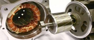
The electric motor (Fig. 8.11) consists of the following assembly units: an armature, a magnetic system (in the housing of which brush holders with brushes are also fixed), bearing shields with armature bearings, removable covers and inspection panels (collector) and ventilation hatches, output wires of the ends windings, motor-axial bearings.
Laying and securing the winding in the grooves of the core is carried out according to the diagram (Fig. 8.12).
Rotation speed (maximum),
cool air, Pa
2TE10, M62, 2TE116, TEM2
Circulation + pol-stern MOS no
2TE116, TEU TEP70, TEP85
2TE120 (AC)
Rice. 8.11. Traction motor type ED118B:
Brush holders 5 have spiral tape springs with stepwise adjustment of pressure on the brushes and are mounted through insulators 7 in detachable brackets 6, welded in one half to the end flange of the electric motor housing. The brush holder device is shown in detail in Fig. 8.14, a.
Bearing shields, in addition to supporting and centering the armature, serve Fig. 8.13. Arrangement of poles of the electric motor ED118B;
a - main; b - additional; 1, 23 - pole core; 2- pole mounting rod; 3, 19 - coil output; 4- electric motor housing; 5, 21 - wavy spring frame; 6, 16 - insulating frame; 7, 14-case coil insulation; 8, 12, 20 - insulating frame; 9- insulating ledge filler; 10, 17-turn insulation; 11, 15 coil conductors; 13, 24 - core insulation; 18- coil output support plate; 22- non-magnetic gasket; 25-non-magnetic support angle Fig. 8.14. Brush holders for traction motors:
The electric motor is installed under the body on the locomotive bogie and is mounted on one side by motor-axle bearings on the axle of the wheel pair, and on the other hand it is supported by special protrusions (“spouts”) of the body (with replaceable linings 24 of increased wear resistance) on the bogie frame through pre-compressed spacer springs. This type of mounting (suspension) of the electric motor is called support-axial.
Other modifications of electric motors produced on the basis of ED125BM differ mainly in the design of the lubrication device for motor-axial bearings or in the complete absence of the latter.
Traction electric motor ED126A. The electric motor is designed for diesel freight locomotives.
Rice. 8.15. Connection diagrams for traction motor windings:
a - four-pole; b - six-pole; c - asynchronous; n, k - the beginning and end of the pole coils; I/, I2 - the beginning and end of the armature winding; D2 - end of the winding of additional poles; C1, C2 are the beginning and end of the series excitation winding for DC electric motors, and for asynchronous electric motors C/, C2, SZ are the output ends of the stator winding phases; 0 is a special output for the protection system. The dashed lines show the connections of the coils on the side opposite to the collector Fig. 8.16. Traction motor type ED125BM:
Traction electric motor ED900.
The operating principle of the electric motor is based on the fact that the rotating magnetic field created by the stator winding induces a current in the short-circuited rotor winding and, under the influence of electromagnetic forces, causes the rotor to rotate. The electrical circuit diagram of the electric motor is shown in Fig. 8.15, e.
Rice. 8.18. Traction asynchronous electric motor type ED900
When operating an electric motor, regular maintenance of the insulation and contact connections of the stator winding terminals, as well as the rotor bearings, is required.
7. set the brushes to normal pressure;
Traction motor malfunctions:
1. all-round fire across the commutator or excessive sparking under the brushes, burnt commutator;
2. grease leaks inside the traction motor;
3. bearing overheating;
4. overlap or breakdown of the brush holder bracket;
5. breakdown of insulation of armature and pole windings;
6. strong sparking under the brushes and current protection tripping;
7. excessive heating of the collector;
8. excessive heating of the armature;
9. torn meshes in the ventilation holes or the remains of bandages sticking out of them;
10. On a motor car, the quick-release switch trips during the first trip after replacing the engine.
The reasons for their occurrence:
1. The brushes are poorly ground to the commutator plates, the fit is loose. The insulation between the collector plates protrudes above them, and the collector is poorly sanded. Unacceptable brush wear, insufficient or uneven brush pressure. Commutator runout, poor quality of brushes, commutator and insulators. The conductor of the armature winding is broken, there is a short circuit in the winding of additional poles. Brush jamming, the commutator is dirty, interturn short circuit or desoldering of the armature winding section from the commutator cockerels;
2. excess lubricant, bearing misalignment;
3. insufficient lubrication, bearing damage;
4. moisture ingress into the traction motor, overvoltage, dirty insulator or brush holder bracket;
5. mechanical damage, a sharp decrease in insulation resistance due to frequent overvoltages on motors, moisture, dust, etc.;
6. mechanical damage to insulation, aging of insulation, decrease in insulating properties due to frequent overvoltages;
7. The brushes are pressed too tightly against the commutator plates;
8. short circuit between sections of armature windings or collector plates;
9. The anchor bands were unwound and some of the debris was thrown towards the ventilation holes;
10. incorrect installation of wires.
Troubleshooting method for traction motor:
1. break in the brushes to the commutator plates at low speeds, clean and polish the commutator. Replace the brushes, adjust the brush pressure, sharpen and polish the commutator. Replace brushes, insulators, repair the winding in the depot, find the damaged coil of the additional pole and replace it (in the depot). Ensure free movement of the brush, clean the commutator, repair the armature in depot conditions;
2. Remove any leaks and observe the bearing assembly. If the damage recurs, remove the traction motor from the trolley, disassemble the bearing assembly and replace the bearing. Eliminate misalignment by tightening the bearing cover bolts;
3. add lubricant. Remove the traction motor from the trolley, disassemble the bearing assembly, replace the bearing and lubricant;
4. wipe the traction motor with a clean cloth moistened with gasoline, replace the insulator or brush holder bracket;
5. eliminate damage in the depot;
6. turn off the traction motor and repair the damage upon arrival at the depot;
7. set the brushes to normal pressure;
8. turn off the traction motor and repair the anchor upon arrival at the depot;
9. turn off the traction motor and repair it upon arrival at the depot;
10. Reconnect the ends of the traction motor.
Characteristics of commutator electric motors used in ground urban transport:
DATE-170 traction motors are included in the KATP-1 traction drive kit installed on cars 81-720.1/721.1 and 81-740/741. Their main parameters:
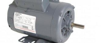
A traction motor (Fig. 1) is a device that is capable of converting incoming electrical energy (AC and DC) into mechanical energy. This type of engine is used to propel the following types of transport:
- electric locomotive,
- diesel locomotive,
- trolleybus,
- tram,
- electric car.
The main difference between such power units and high-power electric motors is that they require certain conditions for installation, as well as a fairly limited space for placement. As a result, a design specification emerged that characterizes the traction motor.
Unlike general-purpose electric motors, traction motors are capable of operating in a variety of modes. These modes are accompanied by a change in the rotor speed.
of traction motors
There are the following types of these devices:
- by current used (DC and AC),
- by design (linear and rotating),
- by type (synchronous and asynchronous),
- according to the force transmission system (individual and group),
- according to the power supply method (from the contact network and from the battery).
Often, the operation of a device such as a traction motor can be associated with mechanical and thermal overloads, shocks and shaking. That is why its design is characterized by increased strength of components and parts - both in the mechanical and electrical parts. Also, current parts have special moisture-resistant and heat-resistant insulation.
The use of traction motors in
electric transport
In connection with the active introduction of environmentally friendly machines into human life, the need arose to use such a device as a traction motor for a car . It is he who is the main driving force in this kind of vehicles. Its operation is based on electromagnetic induction. The driving force occurs in a closed loop as a result of changes in magnetic flux.
Most often, the engine itself is located between the longitudinal beams in front of the battery. A rear axle with a cardan drive is used as a transmission design for the drive wheels. It is permissible to use a chain drive in the case of three-wheeled electric vehicle models. In such a situation, installation is carried out on a subframe on the rear axle.
A traction motor for a car can be either AC or DC. Its main task is to transmit torque. This motor is somewhat different from a classic electromechanical machine due to its compact size and high power.
A traction motor for an electric vehicle can be used in a “motor-wheel” system (Fig. 2), which has not yet found active use and most often can only be seen in concept cars. An exception is the Volage electric car, which will go on sale soon.
The DC traction motor has a number of advantages, namely:
- compact size and light weight,
- ease of use,
- long service life,
- no harmful impact on the environment,
- excellent efficiency,
- possibility of recovery.
It is worth noting that there are simply no significant drawbacks, but one of them is the imperfection of current sources, which do not allow the introduction of this technology into mass production. However, technological progress does not stand still, which means that soon almost every major vehicle manufacturer will start producing cars with electric motors.
We can also talk about such a malfunction as the desoldering of the manifold cockerels, which occurs during periods of excessive overheating of the machine (prolonged overloads, poor ventilation) or as a result of overlap. This problem can only be corrected by repairing the anchor.
- Traction motor - where is it used?
- 1. Traction motor design
- 2. How does a traction motor work?
- 3. Traction motor malfunctions
- 1. Traction motor design
- 2. How does a traction motor work?
- 3. Traction motor malfunctions
Based on the above vehicles, the traction motor is a powerful power unit. So why did we mention electric cars? As it turned out, they are also equipped with this power plant, which has become quite popular among electric vehicle designers. Well, let's get acquainted with the design of this motor, and also consider the principle of its operation and possible malfunctions. So, let's begin…
Traction motor device
Now about all the details in order. The armature of a traction motor consists of a core, winding, commutator and shaft. The armature shaft is usually made of special steel of high quality. But, as practice shows, the shafts also “grow old” and have to be replaced. Based on this, the core sheets are assembled not on the shaft, but directly on a special sleeve. In this case, this design helps to press the shaft out of the bushing without disassembling the core, winding and commutator.
As a rule, one of the main and quite important and responsible components in a given engine is the manifold .
It is the part that bears the most electrical stress. Basically, the conditions for its reliable operation are limited by the maximum power of the traction motors. The collectors of modern traction engines have a diameter of over 800 mm, the number of plates is 600.
In turn, the design of the brush holder includes a body and a bracket connected to each other using a bolt.
In order for the fastening and electrical contact of the housing and the bracket to be more reliable and close, the contacting surfaces have a corrugated surface. It is very important that the brush holder is insulated from the motor frame. Therefore, the brush holder brackets are attached to the frame or bearing shields using insulators.
Now let's talk about the frame. As part of a traction electric motor, the core simultaneously acts as a magnetic circuit, since the main and additional poles are attached to it. As a rule, the core should provide minimal resistance to the passage of magnetic flux. Based on this, it is made of steel, which has good magnetic properties.
How does a traction motor work?
Where the action of this force will be directed (and therefore the direction of rotation) can be determined using the left-hand rule. Following the rule, if you position your left hand so that magnetic lines of force enter the palm (from the north pole of the magnet to the south), and place your fingers in the direction of movement of the current passing through the conductor, then the thumb set aside will show the direction of movement of the conductor.
If it were not there, then the frame, after it takes a certain position, would have to stop, since, according to the left-hand rule, the force of interaction between the magnetic fields of the frame and the magnet will tend to return the frame to a certain position. There are many diagrams on the Internet in which this process is presented clearly. Now let's figure out what malfunctions and breakdowns of the traction motor should be expected and how to carry out a reasonable diagnosis of the breakdown. Read below.
3. Traction motor malfunctions
Before detailing examples of traction motor faults, it is important to say that all faults in electric cars can be broadly divided into breakdowns of electrical and mechanical parts. We are most interested in the electrical part, so when talking about malfunctions, we must definitely mention a decrease in insulation resistance, mechanical damage, insulation aging, breakdowns.
As a result of contamination and wetting of the surface, as well as the entry of moisture, dust and oil into the electric vehicle, the insulation resistance of conductive parts often decreases. To restore the protective properties of the insulation, you need to thoroughly clean the insulation surface and then open it with enamel. You should also always remember that sufficiently deep penetration of moisture will require additional drying.
How to get around this problem? To begin with, experts advise diagnosing the level of overlap intensity. As a rule, in some cases you can only get by by cleaning and flushing the commutator and brush apparatus, as well as replacing brushes that have already failed. In this case, it is also possible to blow out the collector chamber with dry compressed air. In other, more complex cases, repair and replacement of all parts and assemblies that have failed will be required.
We can also talk about such a malfunction as the desoldering of the manifold cockerels, which occurs during periods of excessive overheating of the machine (prolonged overloads, poor ventilation) or as a result of overlap. This problem can only be corrected by repairing the anchor.
Subscribe to our feeds on social networks such as Facebook, Vkontakte, Instagram, Pinterest, Yandex Zen, Twitter and Telegram: all the most interesting automotive events collected in one place.
Sources
Source - https://www.poezdvl.com/electropoezda-metropolitena/rabota-tyagovogo-dvigatelya.html Source - https://www.dieselloc.ru/books/kuzmich/page_37.html Source - https://mobile. studbooks.net/2546296/tovarovedenie/printsip_raboty_tyagovogo_elektrodvigatelya Source - https://wiki.nashtransport.ru/wiki/%D0%A2%D1%8F%D0%B3%D0%BE%D0%B2%D1%8B%D0% B9_%D1%8D%D0%BB%D0%B5%D0%BA%D1%82%D1%80%D0%BE%D0%B4%D0%B2%D0%B8%D0%B3%D0%B0% D1%82%D0%B5%D0%BB%D1%8C Source - https://studref.com/518697/tehnika/printsip_raboty_tyagovogo_dvigatelya Source - https://pomogala.ru/teplovoz/teplovoz_28.html Source - https:/ /rcit.su/techinfoL5.html Source - https://works.doklad.ru/view/miilfgstS_s.html Source - https://cable.ru/articles/id-1643.php Source - https://auto. today/bok/3276-tyagovyy-elektrodvigatel-gde-on-primenyaetsya1.html
Purpose and structure of the bed
Each traction motor is equipped with a frame, used primarily as a magnetic circuit through which the magnetic fluxes of the main and additional poles pass. It also serves as a location and fastening place for poles and bearing protection.
When heavy loads are present, the frame is usually cast from steel or welded from thick electrical steel sheets. Thanks to this design, the required mechanical stability and high magnetic permeability are created. The walls usually have a thickness that provides a specified level of magnetic induction, and its dimensions are oriented towards the cross section of the main poles and are not less than 50% of this size.
The presented figure shows the location of the frame (1) relative to other parts and components - the pole core (2), the field winding coil (3) and the pole shoe (4). There is an air gap (5) between all elements and the anchor. The diameter dimensions from the inside of the frame are calculated so that this space can accommodate the armature, the main and additional poles and their windings.
The locomotive's traction motor may have a cast steel frame with reduced weight and a reduced cross-section oriented toward the axes of the main poles. This makes it possible to evenly distribute the magnetic flux coming to the frame from the main pole.
Pulsating current TED
Pulsating current TED
powered by a single-phase rectifier EPS; current ripple with a frequency of 100 Hz at a rated load of 20-30%. The rated voltage on the collector is 750-1000 V, maximum 1200 V. On electric locomotives, the current strength of the motor is up to 1200 A, power - up to 1000 kW, on motor cars - up to 400-600 A and 300 kW. The TED voltage is regulated by switching the windings of the traction transformer or changing the opening angle of the thyristors (when powered by a controlled rectifier).
The disadvantage of any design of collector TED is the unreliable collector-brush assembly, which limits power and rotation speed (permissible linear speed on the surface of the collector is 50-60 m/s) and requires regular maintenance during operation. The main technical data of the electric motors used on the EPS of the locomotive fleet of Russia and other CIS countries are given in the table.
Main poles
A traction motor operating on direct current includes in its design an excitation winding, where a magnetomotive force appears, which in turn creates a magnetic field. The winding consists of coils placed on the cores of the main poles. On the side of the core directed towards the armature, a pole piece, also known as a shoe, is installed. With its help, the magnetic flux is evenly distributed over the entire surface of the armature. The listed parts are marked in the previous figure along with the frame.
In practice, a circuit that includes a pole core and a pole shoe is quite rarely used. As a rule, they combine into a single whole and form the main pole. Due to this, in the core of the pole there is a decrease in vortex flows caused by the action of pulsations of magnetic induction in the tips due to the serrated surface of the armature.
To assemble the pole, lacquered steel sheets are used, which are then put under a high pressure press. Bolts or special rivets are passed through the core to tighten the entire structure. Their uniform distribution makes it possible to successfully withstand the elasticity of compressed strips. The poles are fastened to the frame using bolts or studs.
Features, pros and cons of automotive TEDs
A breakthrough in the production of traction batteries has significantly increased the demand for electric cars driven by AC traction electric motors.
In most cases, these are asynchronous motors in which the rotor speed does not correspond to the frequency of change in the voltage potential and, accordingly, the magnetic field. Suffice it to say that Tesla S and X are equipped with three-phase asynchronous traction electric motors. They are also called induction, since their electromagnetic force is induced in the rotor according to Lenz’s law. Induction motors are installed on BELAZ-549 with a load capacity of 75 tons.
Synchronous electric motors are used less frequently in the automotive industry, although in general they are quite in demand. For example, climate control technology and many pumping systems are based on synchronous motors.
But there are points in which synchronous TEDs are better than asynchronous analogues. In particular, they better use the vehicle's braking energy for recovery purposes, and such vehicles are quite safe to tow, which cannot be said about a car with an asynchronous motor.
An example of using a synchronous TED is the Renault Zoe model. Here, direct current is supplied to the electromagnets, and the electromotive force arises due to a change in the polarity of the stator magnets (it is constant in the rotor).
Conversations that electric cars are the future are not without foundation. Most technical difficulties have been successfully overcome, the battery recharging infrastructure is developing rapidly, and the design of the engines themselves is constantly being improved.
Advantages of automobile electric motors
Let's look at why TEDs are better than gasoline/diesel engines:
- Unlike an internal combustion engine, a traction electric motor does not require spinning up the shaft as the speed increases: maximum torque occurs immediately after the electric motor is turned on. So a pure electric car doesn’t need a starter or a clutch, and an internal combustion engine won’t be able to work without them;
- the second point is the ease of implementing reverse in the traction electric motor. To engage reverse, just reverse the polarity of the traction motor connection. And no gearboxes;
- in a car with an electric motor, the efficiency reaches 95%, which is even theoretically unattainable for an internal combustion engine;
- an automobile traction electric drive is many times more compact and lighter than an internal combustion engine, which is a significant plus in our age of miniaturization;
- In cars equipped with a gasoline or diesel engine, when braking, all kinetic energy is not wasted, but to the detriment of it, heating the pads and contributing to their faster wear. The ability to use an electric motor as a generator in recuperation mode is beneficial, since during braking, electrical energy is not wasted, but is converted into a form that can feed the traction battery. This effect is especially pronounced in mountainous areas;
- charging the batteries of a traction motor requires less money than is spent on hydrocarbon fuel, and this trend will only increase over time;
- the electric motor operates almost silently;
- forced cooling of the traction motor is not required in most cases, although it is allowed;
- One cannot fail to mention the environmental factor, which is presented by many as the main one.
Flaws
Although the history of electric cars spans more than one decade, their mass distribution was hampered by the imperfection of batteries - a lot of them were required, which increased the weight of the car, they sat down quickly and recharged slowly.
But production technologies for automobile gel batteries have constantly improved, and the current generation can easily provide a total mileage of around 150-200 thousand kilometers. As for the power of electric motors, they are no longer outsiders and are practically not inferior to internal combustion engines in this indicator.
Today, the main disadvantage of electric cars is considered to be an insufficiently developed battery recharging infrastructure, but in the USA, Scandinavian countries and many Western European countries it has already been de facto solved.
In the countries of the former USSR, things are much worse with this. Even a threefold increase in the number of such gas stations in Russia over two years, from 2022 to 2022, did not change the situation. And if in Moscow today recharging a battery is not a problem, then even in other million-plus cities it is much more difficult to do this, not to mention the regions.
Purpose and arrangement of additional poles
Each traction motor with a power of more than 1 kW is equipped with additional poles in order to reduce the number of sparks appearing on the brushes. Their device is very simple, including a core (1) and a coil (2), where a copper conductor is used in insulation. Its cross section is calculated based on the operating current of the motor, since this coil and the armature winding are connected in series to each other.
The steel core is made in the form of a monolithic structure, due to the absence of eddy currents in it, since the magnetic induction is very small. The location of installation of additional poles is determined by the gap between the main poles, and fastening to the frame is carried out with special bolts. The size of the air gap under them significantly exceeds the gap under the main poles. Its adjustment is carried out using special plates made of magnetic or non-magnetic materials, and the final value is determined when the DC traction motor is set to switch when the minimum number of sparks is reached.
Classification of traction electric motors
Currently, both electric motors powered by direct current and varieties whose source of electricity is alternating current are actively used. There are also traction motors that operate from pulsating current.
Let's consider other TED classifiers.
Type:
- synchronous electric motors;
- TED of sequential excitation;
- Asynchronous traction motors.
By power source:
- autonomous (battery, fuel cell, generator);
- contact network (electric trains, metro, trolleybuses).
According to the prevailing operating mode:
- short-term (one working cycle – 20-80 minutes);
- long lasting;
- repeated-short-term.
By design:
- brushless (valve or contactless type motors) traction motors;
- collector TED;
- rotating;
- linear.
By cooling type:
- blown;
- autonomous ventilation;
- natural ventilation;
- self-ventilation.
In addition, traction electric motors are classified by climatic design (standards are given in GOST 15150/15543) and by degree of protection.
Anchor and manifold
The armature consists of a shaft, core, windings and commutator. The core configuration is made in the shape of a cylinder, and it itself is made of thin stamped sheets of electrical steel. To insulate the sheets, varnish or paper is used. In a compressed form after assembly, the core is fixed with pressure washers. Thanks to the design of the core, it is possible to compensate for the influence of eddy currents and reduce the leakage of electricity in it. Cooling of the TED is carried out due to special ventilation channels arranged in the core.
For armature windings, a copper conductor of round or rectangular cross-section is used. It is placed in the recesses of the core and is qualitatively insulated from it. The entire winding is divided into sections, the ends of each of them are connected to the collector by soldering.
The design of each collector includes an active component and a fastening system. The copper collector plates (7) are insulated using special gaskets. The armature winding wires are soldered to the protrusion at the end of the element (5). The edge of the plates located at the bottom (6) after assembly is clamped using two pressure rings (3). These rings are also insulated, and the insulation itself is recessed 1.5 mm inside the sliding surface of the collector.
Nutrition
Nutrition
TED is carried out from the contact network (EPS) and from the energy source located on the rolling stock (electric machine generator, battery). Based on the type of current, TEDs are divided into collector DC (current ripple up to 10%), collector pulsating current powered by a single-phase rectifier, and brushless AC asynchronous (single-phase, multiphase) and synchronous (valve) with the conversion of single-phase current into multiphase (usually three-phase ). Rectifiers and converters are placed on the rolling stock, which makes it possible to regulate the voltage on the electric motor. When powered by direct voltage current from the contact network, voltage regulation on the electric motor until the 1970s. was carried out by switching the motors to a serial or parallel connection and including starting resistors in the circuit. From the beginning 70s on electric locomotives VL80R and in the future, stepless smooth voltage regulation is usually carried out by semiconductor controlled rectifiers or converters located on the EPS.
Asynchronous TED
Asynchronous TED
has a rotor with a short-circuited winding without insulation; The stator winding is made with insulation. At the EPS, an asynchronous TED receives power from static converters built on the basis of autonomous voltage or current inverters. Regulation of the operating modes of the electric motor, carried out by changing the voltage and its frequency (two independent control channels), can be carried out individually for each electric motor or simultaneously for several. The operating traction characteristics of the engine are shown in Fig. 5.58.
Characteristics of TED
The characteristics of TED are divided into electromechanical, thermal and aerodynamic. To electromechanical characteristics
relate the dependences of the armature rotation frequency n, the motor torque M and the efficiency on its shaft ηd on the armature current Ia, as well as the ratio of the voltage in the armature windings (emf) to the rotation frequency E/n depending on the excitation current Ib. The last dependence is nonlinear due to the saturation of the magnetic circuit of the machine at a high excitation current (Fig. 5.57).
The main calculated dependencies for any DC electric machine are as follows:
Re = Ela = 1.028 Me*n; E=c*Ф8n; U = E + IaR; η=Р2/Р1,
where Re, Me - electromagnetic power and torque (in the air gap), P1 = U*Ia, P2 = P1-ΣΔP - power at the terminals (clamps) and shaft, U - voltage at the terminals of the machine.
Instructions for maintenance and routine repairs
Repair and diagnostics of PC
I. Instructions for safety measures. II. Types and frequency of maintenance
Mechanical equipment TO-2 Electrical machines TO-2 Transformers, chokes TO-2 Electrical devices TO-2 Pneumatic equipment TO-2 Ventilation system TO-2
Mechanical equipment TR-1 Electrical machines TR-1 Transformers, chokes TR-1 Electrical devices TR-1 Pneumatic equipment TR-1 Installation of equipment TR-1 Installation of wires and tires TR-1 Ventilation system TR-1
Mechanical equipment TR-2 Electrical machines TR-2 Transformers, chokes TR-2 Electrical devices TR-2 Pneumatic equipment TR-2 Installation of equipment TR-2 Installation of wires and tires TR-2 Ventilation system TR-2
Mechanical equipment TR-3 Electrical machines TR-3 Transformers, chokes TR-3 Electrical devices TR-3 Pneumatic equipment TR-3 Installation of equipment TR-3 Installation of wires and tires TR-3 Ventilation system TR-3 Testing of an electric locomotive after routine repairs TR- 3
List of machines and devices List of technical documentation for components List of instructions and rules of the Ministry of Railways of the USSR List of checks of the technical condition of components and parts of the mechanical part of an electric locomotive Lubrication chart for electric locomotive components Troubleshooting in the NB-418K6 traction motor after transfer and all-round fire Typical malfunctions of the NB-418K6 traction motor in operation and methods for their elimination Determination of the tension of the brushes and the commutator of the NB-418K6 traction motor Installing the brushes in the neutral position on the NB-418K6 traction motor Drying the moistened insulation of the windings of the NB-418K6 traction motor Standards for tolerances and wear of the NB-418K6 traction motor Features of maintenance of traction motors NB-418K6 in winter Drying auxiliary electrical machines Preparing auxiliary electrical machines for operation Features of operating auxiliary electrical machines in winter Standards of tolerances and wear of auxiliary electrical machines Typical malfunctions of auxiliary machines and methods for eliminating them Norms of tolerances and wear of parts of electrical devices Typical malfunctions of electrical devices and methods their elimination List of switchboard devices Preparation of fans for operation Resistance of device coils List of sealable devices and equipment Technical data of resistors Technical data of capacitors List of fuses Trigger settings of protection and control devices Standard values of test voltage and insulation resistance for checking the electrical strength of equipment and its circuits Purpose of electrical contacts devices in electric locomotive control circuits