Switched motor diagram
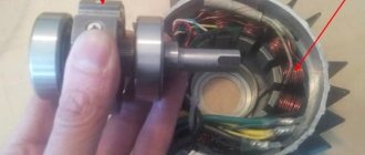
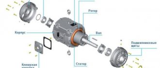
The engine consists of the following parts:
1. Back of the case. 2. Stator. 3. Bearing. 4. Magnetic disk (rotor). 5. Bearing. 6. Stator with winding. 7. Front part of the body.
The switch motor has an interconnection between the multiphase stator and rotor windings. They have permanent magnets and a built-in position sensor. Switching of the device is realized using a valve converter, which is why it got its name.
The switch motor circuit consists of a back cover and sensor circuit board, bearing bushing, shaft and bearing itself, rotor magnets, insulating ring, winding, triangular spring, intermediate bushing, Hall sensor, insulation, housing and wires.
In the case of a star connection of the windings, the device has large constant moments, so this assembly is used to control axes. If the windings are fastened in a triangle, they can be used to work at high speeds. Most often, the number of pole pairs is calculated by the number of rotor magnets, which help determine the ratio of electrical and mechanical revolutions.
The stator can be manufactured with an iron-free or iron core. Using such designs with the first option, it is possible to ensure that there is no attraction of the rotor magnets, but at the same time the engine efficiency is reduced by 20% due to a decrease in the constant torque value.
The diagram shows that in the stator the current is generated in the windings, and in the rotor it is created using high-energy permanent magnets. Legend: - VT1-VT7 - transistor communicators; — A, B, C – winding phases; — M – engine torque; — DR – rotor position sensor; — U – motor supply voltage regulator; — S (south), N (north) – direction of the magnet; — UZ – frequency converter; — BR – speed sensor; — VD – zener diode; — L – inductor.
The motor diagram shows that one of the main advantages of a rotor in which permanent magnets are installed is a reduction in its diameter and, as a result, a reduction in the moment of inertia. Such devices can be built into the device itself or located on its surface. A decrease in this indicator very often leads to small values of the balance of the moment of inertia of the motor itself and the load reduced to its shaft, which complicates the operation of the drive. For this reason, manufacturers can offer standard and 2-4 times increased moment of inertia.
Engine design and device
The technical infrastructure is formed by two segments - the mechanics itself and the control complex. From the point of view of the structural design, the unit is in many ways similar to the traditional filling of electromechanical rotary engines. Accordingly, the electric motor includes a rotor, stator and winding. Moreover, the stator is a set of separate insulated sheets made of steel alloy. During operation, they help reduce eddy currents. It contains the winding, which can have a different number of phases. The filling of the element is formed by a steel core, and the winding is made of copper fibers. For protection, a housing is used, on the surface of which means of physical fastening are also provided.
As for the rotor, it is formed by permanent magnets. Depending on the modification, it can have up to sixteen pairs of alternating poles. Previously, ferrite magnets were used to manufacture rotors, which was due to their affordability. Today, the operational characteristics of a valve motor come to the fore - in particular, torque, which varies from 1 to 70 Nm. The throughput frequency is on average within 2-4 thousand revolutions. To achieve such performance, a magnet with a high degree of induction is required, so manufacturers have switched to the use of rare earth alloys. Such magnets not only provide higher performance, but are also smaller in size. In part, this transition also contributed to the optimization of the dimensions of the valve motor. It is worth considering separately the components of the management segment.
Work principles
Today, a valve motor is becoming very popular, the operating principle of which is based on the fact that the device controller begins to switch the stator windings. Due to this, the magnetic field vector always remains shifted by an angle approaching 900 (-900) relative to the rotor. The controller is designed to control the current that moves through the motor windings, including the magnitude of the stator magnetic field. Therefore, it is possible to regulate the torque that acts on the device. The angle between the vectors can determine the direction of rotation that is acting on it.
It must be taken into account that we are talking about electrical degrees (they are much smaller than geometric ones). As an example, we give a calculation of a rotor motor with a rotor that has 3 pairs of poles. Then its optimal angle will be 900/3=300. These pairs provide 6 phases of the commutation windings, then it turns out that the stator vector can move in jumps of 600. From this it is clear that the real angle between the vectors will necessarily vary from 600 to 1200, starting with the rotation of the rotor.
A valve motor, the operating principle of which is based on the rotation of the commutation phases, due to which the excitation flow is maintained by a relatively constant movement of the armature, after their interaction begins to generate a rotating torque. He rushes to turn the rotor in such a way that all the excitation and armature flows coincide together. But during its reversal, the sensor begins to switch the windings, and the flow moves to the next step. At this moment, the resulting vector will move, but will remain completely motionless compared to the rotor flux, which will ultimately create shaft torque.
Features of asynchronous units
In asynchronous motors, the rotor does not rotate in the opposite direction. It cannot be called the opposite of a synchronous unit from the point of view of the interaction of the magnetic fluxes of the rotor and stator. Both synchronous and asynchronous motors involve the following of one field after another. Another thing is that in the second case, the rotor, for example, can be “catching up”. It follows the generation of an induction torque.
In the standard design, the stator generates an electromagnetic field, causing the rotor to rotate after a certain time. The fundamental difference between the two types of motors is that the inductor is not a generator of excitation of the rotor magnetic field. Therefore, an asynchronous type valve motor can autonomously force the rotor to rotate at a certain frequency from the stator winding. This does not mean that the two mechanisms operate separately, but their functions are not as closely interrelated as in the case of synchronous motors. The same applies to speed. For example, if in a synchronous unit there is a rotation speed of 3000 rpm for the inductor and rotor, then the asynchronous operating principle for the same rotor can reduce this value to 2910 rpm.
Advantages
When using a valve motor in operation, one can note the following advantages:
— possibility of using a wide range for modifying the rotation speed;
— high dynamics and speed;
— maximum positioning accuracy;
— low maintenance costs;
— the device can be classified as an explosion-proof facility;
— has the ability to withstand large overloads at the moment of rotation;
— high efficiency, which is more than 90%;
— there are sliding electronic contacts that significantly increase the working life and service life;
— during long-term operation there is no overheating of the electric motor.
Advantages and disadvantages
In comparison with other types of electric machines, a valve motor has a number of qualitative differences that give it both advantageous superiority and certain disadvantages.
The advantages of valve motors include:
- Relatively small amount of magnetic losses due to the absence of a constantly operating field, as in classical synchronous and asynchronous electric motors.
- Ensures safe rotation even with maximum load, unlike commutator motors.
- Due to the built-in frequency converter, switching of the valve converter provides a wide range of rotation speeds, which are distinguished by a smooth transition from one to the next.
- Good operating dynamics and positioning accuracy that can compete with stepper motors.
- Relatively high degree of reliability and long service life without maintenance due to the absence of sliding contact, unlike commutator motors.
- Can be used in explosive environments, unlike DC and AC electric motors with brushes.
The disadvantages of valve units include their high cost and the presence of additional elements that complicate subsequent operation. Also considered a significant disadvantage is the complexity of controlling and setting the logic for moving the working bodies of three-phase brushless motors in accordance with changing factors of the production process.
Switched reluctance motor
A switched reluctance motor is a device that has a switching magnetic resistance. In it, energy conversion occurs due to changes in the inductance of the windings, which are located on pronounced stator teeth when the toothed magnetic rotor moves. The device receives power from an electrical converter, which alternately switches the motor windings according to the movement of the rotor.
A switched reluctance motor is a complex complex system in which components that are diverse in their physical nature work together. Successful design of such devices requires advanced knowledge of machine design and mechanics, as well as electronics, electromechanics and microprocessor technology.
The modern device acts as an electric motor operating in conjunction with an electronic converter, which is manufactured using integrated technology using a microprocessor. It allows for high-quality engine control with the best energy conversion performance.
Disadvantages of the electric motor
Experts note two main disadvantages of such electric motors. First of all, this is the complexity of the design. Not the mechanical part, but the electronic base that provides control of the motor. The use of microprocessors, sensors, inverters and related electrical fittings requires an appropriate approach to ensuring the reliability of the system components. Thus, the cost of equipment maintenance also increases. At the same time, the high cost of the magnets on which the valve motor is based, even in simple single-phase versions, is also noted. In practice, users try to replace expensive elements and consumables, while at the same time simplifying the control system. But such measures themselves require certain resources, not to mention the fact that engine efficiency decreases.
Engine properties
Such devices have high dynamics, high overload capacity and precise positioning. Due to the fact that they have no moving parts, their use is possible in explosive aggressive environments. Such motors are also called brushless; their main advantage, compared to brushed motors, is the speed, which depends on the supply voltage of the loading torque. Also, another important property is the absence of abrasive and rubbing elements that switch contacts, due to which the service life of the device increases.
Technologies do not stand still, and the improvement of precision equipment creates new devices. These types include electric machines that have already replaced the old brushes; instead, they use a contactless valve motor.
Article outline:
- What is a valve motor
- Design
- Design of valve apparatus wrestler
- Engine design:
- Specifics of leadership on continuous current
- Specifics of performance on alternating current
- Application of a valve motor
- The principle of movement of the vector apparatus
- Types of product phases
- Advantages and disadvantages
- Valve inductor drive
- Advantages of a valve inductor drive
- Conclusion
Valve motor with constant and alternating current, mechanism design
A semiconductor key, of course, under the word “valve”, in which the operating mode is specially regulated on keys with a semi-drive.
Valve motor - (VD) is one of the subtypes of the electronic heart of a constant electric flow, simple in design, in which the control panel (brush-commutator unit) is replaced by a semiconductor conductor, and is controlled by a stator position meter. Sometimes such a sensor is not available and the location is measured using observers, this type is called a sensorless application.
The brush device reduces strength, increasing the moment of inertia, and creates radio interference or even an explosion hazard, which is why a non-contact engine was created, in which coil windings ensure high manufacturability of the device design. In the mechanism, the armature is stationary, and the stabilizer is an unchangeable magnet.
Design of valve apparatus wrestler
The diffusion tool contains three subsystems:
- Electronic
- Mechanical
- Electrical
Multiphase inductor centers have different applications, have a strong frequency-controlled tool, and also have such qualities as non-contact, high reliability, cost-effectiveness, long service life, not strongly limited by power and voltage values, speed, simplicity and cheap to repair. In addition, it is possible to use the unit on a cordless screwdriver, since with its help you can obtain high efficiency indicators and high-quality product performance by reducing weight.
Engine design:
- Rotor - reacts to the influence of the electromagnetic field. The basis is a magnet, and it has diverse pairs of poles (2 -8) with their alternation. More modern instructions equip it with rare earth materials, which emit more magnetic induction and make the electronic organism more compact.
- Stator - winding phases wound on coils and a dielectric spacer. Basically, the windings are connected by a star or delta structure. The most common phase is considered to be a three-phase structure. The “star” is more often used for large moments of change in direction, and the “triangle” for high speeds.
- Position sensors and temperature sensor - determine the rotation position of the shaft. It is done using different methods - for example, the Hall effect, photoelectric and others. Counting measures are made without pausing at a certain starter position.
The photoelectric sensor has three stationary receivers. They alternately shade and rotate in the same direction as the stator. The code comes from them and records the positions of the stabilization equipment, of which there are six. The device converts the signals into pulses to feed the stream, and they already control the semiconductor switches.
The temperature sensor in a phase motor is a brake. The tachogenerator is used when the motor is produced in speed stabilization mode.
- A block with a microprocessor – generates pulses, the shape and speed of rotation of the propulsion, compares readings on flow and winding sensors
There are two types of units: non-contact alternating current and irreplaceable current. It is important to distinguish a bypass motor from a brushless motor (BLDC), such as a rectangle and distributes the field of attraction in a trapezoid-shaped gap. The structure of the BLDC motor is not as complex (but it is not discussed in the article) as the structure of a valve, the implementation of switching is not as complicated as using PWM, 120 - 180 degree switching is performed).
In the CNC (Computer Numerical Control) system, the valve gear mechanism is widely used among electric motors, the performance of which is superior to other drive systems.
In a given control block diagram, the controller performs:
- DC converter voltage adjustment;
- Protection of power modules from overvoltage in the power supply network, or from accidents;
- During acceleration, phase currents are cut off;
- Rotation stabilization and automatic phase switching;
- Acceleration and braking;
- Setting the position of the mover at the desired angle;
- Nutrient system monitoring.
Specifics of leadership on continuous current
It induces magnetic declinations on the ferromagnetic stabilizer. Magnetic resistance can be created by a spinning screw. Continuous flow valve preparations are mainly used in oil production, drilling equipment, cooling machines and chemical industries.
Specifics of performance on alternating current
It is used as vector or frequency-current algorithms for automatic control of a device with the torque and rotation frequencies of the PMSM. The operation of power transmission depends on the accuracy of available information about processes that can change. All these mechanisms are used by electric drives, bridges and foreign companies.
According to the method of action of the magnetic field of the stator and rotor, there are: synchronous, asynchronous and inductive tools. The adjustment occurs using an inverter - an electronic voltage supply system in which the frequencies do not depend on the supply voltage to the electric motor windings. To a greater extent, simultaneous devices are equipped with an inverter, but in fact, there are also asynchronous ones - to adjust the rotation frequency.
There are only two purposes for valve motor controls:
- Switching (six pulse)
- Vector
Tuning by binding is when the field is adjusted to the speed of rotation in the stabilizer plate. The mechanism establishes rotation by changing the flux or wire applied to the commutation windings.
The vector control method is easy to control the machine. Its use is very effective on short lines, but for use on long lines it makes the purpose of the unit more difficult, and the solution to such a problem will be quite complicated.
Where can a mechanical machine engine be used?
The valve unit can be used in a large number of areas of speed control and rotation of workable products. Such simultaneous meters have precise positioning and can be used for computer systems, propulsion devices, hard drives, various types of coolers and other electric vehicles.
Continuing, you can use it with different sets of robotics, satellites and aircraft structures. Household appliances are no exception; automotive and medical industries also welcome the work of valve motors. Wide use is possible in machine tools of various classes, mining devices, at stations or compressor units and various SEP compositions.
It can be added that mainly disk, traction motors with power from kW and 270V power supply are used for the transport of city cars. Steering adjustments of underwater, land and aircraft, wheel motors and others use valve motors. At the same time, submersible valve motors of the Novomet family are often used for efficient use in oil companies.
The principle of movement of the vector apparatus
A vector mechanism is a system of regularity of an adjustable starter, in which there is an electronic motor of variable direction, as in synchronous machines, a balancing converter and a control device with permanent magnets. With the help of control, the circuits on the heart winding are switched, depending on the position of the engine. A phase motor is similar to a non-variable current motor, in which the armature, instead of a commutator, is located under the excitation poles. During magnetic movements, sensors detect their position and change the throughput of the reactive valve converters, which allows the body to rotate.
For a simple understanding, you can imagine a compass, where the heart of a synchronous machine will be a magnetic needle, and the stator field will be the magnetic field of the planet. Without an external load, the stabilizer is always focused on the stator field (just as there are no such loads in a compass). By twisting the compass, the needle will rotate along its directional axis. Since the stator field is created by electromagnets, using a coil and fluxes.
The circuits and principle of the product are as follows: the stator creates a magnetic field, directing it in the desired direction with a given amplitude. Since in the picture in the center there is a magnet - the equipment for starting movement (compass needle), and on the side there are electromagnets - coils in which its own field is created (vertical and horizontal drawn axes). (Fig. 1).
The magnetic current in the coil is proportional to the voltage inside. We need the flux from the stator where the stator lies (in the center). Two perpendicular coils are added along a vector and, together with the rotor, form a common strum. The total direction of the current in the stators created the direction of the stator flow in one common direction.
Also, based on the number of phases, motors are divided into types:
- Single-phase - the simplest mechanism, which uses a minimum of voltage transmission lines to the windings from regulation. But, in some events the weapon has difficulty launching due to the load
- Two-phase - have a very good connection between the stator and the winding. Can lead to poor performance consequences due to fairly strong pulsations
- Three-phase - the most common option, they start smoothly, and the electrode converter plows in normal mode. Even number of windings and pretty good traction capabilities. The only downside is the noise.
- Four-phase - characterized by low ripples and starting torque movement. Also one of the disadvantages is the high cost, so they are rarely used.
Motors of the 5DVM series of rockers - the presence of three-phase synchronous units with flange mounting and excitation from rare-earth magnets. Designed for use as part of settings with high dynamic characteristics with a wide range of speed adjustments. Also used in machines with mathematical calculation controls, in the production of technological lines and others.
Advantages of valve motors
Compared to other electric motors, the adjustment module has a number of advantages that improve its characteristics compared to older subtypes
- There are no components in the engine and no equipment maintenance is required;
- Contactless. Safe rotation with minimum load;
- High resource. Large overload capacity and large starting instant;
- Fast response and large rotation radius;
- Better efficiency indicators than asynchronous motors;
- Minimum starting currents and quickly pays for itself;
- Long service life due to the absence of sliding contact;
- Can be used in explosive environments.
What are the disadvantages for large constant current motors?
- The presence of a brush-collector unit;
- Low reliability of the collector tool;
- The effect on the anchor is compressed, which is why the power will not be great;
- The overload capacity of the main tool of constant voltage, as well as the duration of action with a change in current in the armature, are limited;
- High cost for equipment and difficulty in mechanization.
Technical characteristics of the valve motor
- A small load determines the content, it is sent to the pressure apparatus to gain force;
- Energy consumption – the heart shows the amount of power taken to use the engine;
- Efficiency is the proportion of the work done by the valve apparatus and the force used;
- Gross force is a useful ability of the engine, due to the force of gravity;
- Normal frequency is the composition of revolutions per minute with which the tool makes in the nominal mode of operation;
- Frequency control range – the limit of change in shaft speed for a particular model;
- Normal torque - the definition of the attempt - is created on the valve shaft with standard product parameters and can be regulated by starting and minimum speeds;
- Load factor – represents how much the efficiency of the electrical collector can be reduced above sea level;
- Dimensions and weight of the required equipment.
Characteristics of a Russian electric motor based on an inductive mechanism
The valve inductor drive is a domestic VIP, perhaps one of the oldest Soviet electronic engines. The design also has a magnetic system, with highly pronounced gearing of varying amounts on the stator and mover. Sequential phase switching helps turn the starter in the desired direction. Also, the motor is represented as a self-excited inductive machine (variable flux in the stator), because the magnetic field is created by the stator pole coils and receives power.
The advantages of such a unit are considered to be a rather simple, reliable and cheap engine design, which is used in agriculture, because it does not have complex technologies to use. VIP is superior to frequency-controlled asynchronous transmission in multitasking performance. In Russia, the development of such an inductive electrical device was started by Professor N.F. Ilyinsky in 1995, under whose leadership MPEI carried out systematic research and development of traditional VIPs corresponding to world experience (SRD) and the Esson design system.
Advantages of a switched inductor device:
- Reliability of products (non-contact);
- Easy to use;
- Adaptation to the most modern guidance methods - a vector guidance system can be created with support for electromagnetic motion and speed;
- High efficiency rates of more than 98%;
- Speed adjustment up to 5 times due to additional excitation control;
- Formation of the necessary engine characteristics;
- Customize the software;
- Increasing capacity by increasing sections and using standard modules;
- The transition of power supply from 10 kV to 0.4 kV allows you to place power cabinets at a minimum distance from devices.
Conclusion:
Generally speaking, in the standard form of understanding, an electrical measuring instrument is not a completely electrical instrument, since in order to confirm an electronic motor it is necessary to attach importance to a number of issues relevant to our topic of theory and automatic control circuits. CHEAZ employees will help the interested person to resolve any problems related to this topic. Aggregate machines, which also have single and alternating current in stock, serve as an alternative to such motors. The reason, as written in the article, is that in the constant flow range there are a number of problems associated with the control panel, interference, tool wear and poor conductor armatures. Therefore, it is better to use valve motors instead of the old ones with brushes, and the mechanism can be used in difficult places or where DFC cannot be used at all.
DC valve motors
All DC motors can be called brushless motors. They operate from a direct current network. The brush assembly is provided to electrically connect the rotor and stator circuits. This part is the most vulnerable and quite difficult to maintain and repair.
A DC valve motor operates on the same principle as all synchronous devices of this type. It is a closed system that includes a power semiconductor converter, a rotor position sensor and a coordinator.
Features of synchronous models
The above operating principle just illustrates the operation of a synchronous motor. That is, it implements the interaction of the poles of the inductor and the stator magnetic field. But even such systems may have their differences. For example, both synchronous and asynchronous motors can be equipped with electromagnets. In the case of synchronous units of this type, the current will be directed to the rotor, bypassing the brush-ring contact. Permanent magnets are used in motors based on hard drives. There are also inverted designs. In them, the armature fluxes are on the rotor, and the induction is on the stator.
To switch on a synchronous motor, a high frequency acceleration is required in order to be able to adjust the rotation of the two functional components. In designs where the inductor is located on the stator, the rotor field remains stationary relative to the armature. Conversely, if the device assumes the opposite design, then “entry into synchronization” will be carried out through waiting for the stator. The waiting moment depends on what load the valve motor is operating with and what frequency is optimal for activating its inductor.
AC fan motors
Such devices receive their power from AC mains. The rotor rotation speed and the movement of the first harmonic of the stator magnetic force completely coincide. This subtype of engines can be used at high power. This group includes stepper and reluctance valves. A distinctive feature of stepper devices is the discrete angular displacement of the rotor during operation. The power supply to the windings is generated using semiconductor components. The valve motor is controlled by sequential displacement of the rotor, which creates a switching of its power from one winding to another. This device can be divided into single-phase, three-phase and multi-phase, the former of which may contain a starting winding or a phase-shifting circuit, and can also be manually started.
Types of electric motors
The following types of DC motors exist:
- with excitation using permanent magnets;
- with a series connection of the armature and field windings;
- with parallel connection of armature and field windings;
- with mixed connection of armature and field windings;
- valve motor (brushless DC motor), made using a closed system; This type of motor uses an inverter (power semiconductor converter), a coordinate converter and a rotor position sensor.
An AC motor is an electric motor that is powered by alternating current. The following types of AC motors exist:
- hysteresis motor;
- switched reluctance engine;
- an asynchronous electric motor with a rotor speed different from the speed of the magnetic field generated by the voltage;
- synchronous electric motor with a rotor speed that matches the speed of the magnetic field created by the voltage.
There is also a UKM (universal commutator motor) with the function of operating on both alternating and direct current.
Another type of motor is a stepper motor with a finite number of rotor positions. A certain specified position of the rotor is fixed by applying power to the necessary corresponding windings. When the supply voltage is removed from one winding and transferred to others, a process of transition to another position occurs.
An AC motor, when powered via an industrial network, usually does not allow a rotation speed of more than three thousand revolutions per minute. For this reason, if it is necessary to obtain higher frequencies, a commutator motor is used, the additional advantages of which are lightness and compactness while maintaining the required power.
Sometimes a special transmission mechanism called a multiplier is also used, which changes the kinematic parameters of the device to the required technical parameters. Commutator units sometimes take up up to half the space of the entire engine, so AC electric motors are reduced in size and made lighter in weight by using a frequency converter, and sometimes due to the presence of a network with an increased frequency of up to 400 Hz.
The service life of any AC asynchronous motor is noticeably higher than that of a commutator motor. It is determined by the state of the insulation of the windings and bearings. A synchronous motor, when using an inverter and a rotor position sensor, is considered an electronic analogue of a classic brushed motor that supports operation via direct current.
Operating principle of a synchronous motor
A valve synchronous motor operates based on the interaction of the magnetic fields of the rotor and stator. Schematically, the magnetic field during rotation can be represented by the pluses of the same magnets, which move at the speed of the stator magnetic field. The rotor field can also be depicted as a permanent magnet that rotates synchronously with the stator field. In the absence of external torque applied to the shaft of the device, the axes completely coincide. The influencing forces of attraction run along the entire axis of the poles and can compensate each other. The angle between them is equal to zero.
If a braking torque is applied to the machine shaft, the rotor moves to the side with a delay. Thanks to this, the attractive forces are divided into components, which are directed along the axis of the positive indicators and perpendicular to the axis of the poles. If an external moment is applied, which creates acceleration, that is, begins to act in the direction of rotation of the shaft, the picture of the interaction of fields will completely change to the opposite. The direction of the angular displacement begins to transform to the opposite, and in connection with this, the direction of the tangential forces and the effect of the electromagnetic moment change. In this situation, the engine becomes a brake, and the device operates as a generator, which converts the mechanical energy supplied to the shaft into electrical energy. It is then redirected to the network that powers the stator.
When there is no external moment, the salient pole moment will begin to take a position in which the axis of the poles of the stator magnetic field will coincide with the longitudinal one. This placement will correspond to the minimum flux resistance in the stator.
If a braking torque is applied to the machine shaft, the rotor will deflect, and the magnetic field of the stator will be deformed, since the flow tends to close according to the least resistance. To determine it, lines of force are needed, the direction of which at each point will correspond to the movement of the force, so a change in the field will lead to the appearance of tangential interaction.
Having considered all these processes in synchronous motors, it is possible to identify the demonstrative principle of reversibility of various machines, that is, the ability of any electrical apparatus to change the direction of the converted energy to the opposite.
Classification
According to the type of power supply, switched-type electric machines are divided into direct and alternating current electric motors.
According to the method of interaction of the magnetic field of the stator and rotor, there are synchronous, asynchronous and inductor devices.
In addition, depending on the number of phases involved, they are divided into:
- Single-phase - this is the simplest option, which uses a minimum of power supply lines from the control unit to its windings. However, in some situations it is difficult to start such a switch motor under load.
- Two-phase - have a good connection between the winding and the stator. But they produce quite strong pulsations, which can lead to negative consequences in operation.
- Three-phase are the most common options, capable of providing a soft start and normal operation of a brushless motor. Characterized by an even number of windings and good traction characteristics. Its only disadvantages include excessive noise during operation.
- Four-phase - characterized by minimal ripple and low starting torque. But, in comparison with other models, they have a high cost, which is why they are rarely used.
Rice. 7. Four-phase brushless motor
Permanent Magnet Brushless Motors
The permanent magnet motor is used to solve serious defense and industrial problems, as such a device has a large reserve of power and efficiency.
These devices are most often used in industries where relatively low power consumption and small dimensions are required. They can have a variety of dimensions, without technological restrictions. At the same time, large devices are not completely new; they are most often produced by companies that seek to overcome economic difficulties that limit the range of these devices. They have their advantages, including high efficiency due to rotor losses and high power density. To control brushless motors, you need a variable frequency drive.
Cost-benefit analysis shows that permanent magnet devices are far superior to other alternative technologies. Most often they are used for industries with fairly heavy operation of ship engines, in the military and defense industry and other departments, the number of which is constantly increasing.
Advantages of electric motors
Thanks to design optimization, valve power technology offers many operational advantages. Among them, it is worth noting speed, flexibility in configuration, accuracy in determining the rotor position (using a sensor), wide possibilities for technical adjustment, etc. With modest energy consumption, you can get high power output. What is also important is that the valve motor uses a small resource of mechanical action, and this has a beneficial effect on its service life. The low level of thermal impact on the element base ensures the absence of overheating, so parts only in rare cases require replacement due to wear.
Jet engine
A switched reluctance motor operates using two-phase windings that are mounted around diametrically opposed stator poles. The power supply advances to the rotor according to the poles. Thus, its opposition is completely reduced to a minimum.
The hand-crafted valve motor provides highly efficient drive speed with optimized magnetism for reverse operation. Information about the location of the rotor is used to control the phases of voltage supply, as this is optimal for achieving continuous and smooth torque and high efficiency.
The signals produced by the reluctance motor are superimposed on the angular unsaturated phase of the inductance. The minimum pole resistance fully corresponds to the maximum inductance of the device.
A positive moment can only be obtained at angles when the indicators are positive. At low speeds, the phase current must be limited to protect the electronics from high volt-seconds. The conversion mechanism can be illustrated by a reactive energy line. The power sphere characterizes nutrition, which is converted into mechanical energy. In the event of a sudden shutdown, excess or residual force is returned to the stator. The minimum indicators of the influence of the magnetic field on the performance of the device are its main difference from similar devices.
Brushless DC motor. General information and device design
A brushless DC motor is also called a three-phase brushless DC motor. It is a synchronous device, the operating principle of which is based on self-synchronized frequency regulation, due to which the vector (based on the position of the rotor) of the stator magnetic field is controlled.
Motor controllers of this type are often powered by constant voltage, which is where they get their name. In English technical literature, a valve motor is called PMSM or BLDC.
The brushless motor was created primarily to optimize any DC motor in general. Very high demands were placed on the actuator of such a device (especially the high-speed microdrive with precise positioning).
This, perhaps, led to the use of such specific direct current devices, brushless three-phase motors, also called BLDC motors. In their design, they are almost identical to synchronous AC motors, where the rotation of the magnetic rotor occurs in a conventional laminated stator in the presence of three-phase windings, and the number of revolutions depends on the voltage and load of the stator. Based on certain coordinates of the rotor, different stator windings are switched.
Brushless DC motors can exist without any separate sensors, however, sometimes they are present on the rotor, such as a Hall sensor. If the device operates without an additional sensor, then the stator windings serve as a fixing element. Then the current arises due to the rotation of the magnet when the rotor induces an EMF in the stator winding.
If one of the windings is turned off, the signal that was induced will be measured and further processed, however, this operating principle is impossible without a signal processing professor. But to reverse or brake such an electric motor, a bridge circuit is not needed - it will be enough to supply control pulses in reverse sequence to the stator windings.
In a VD (switched motor) an inductor in the form of a permanent magnet is located on the rotor, and the armature winding is on the stator. Based on the position of the rotor, the supply voltage for all windings of the electric motor is generated. When a collector is used in such designs, its function will be performed by a semiconductor switch in a switch motor.
The main difference between synchronous and valve motors is the self-synchronization of the latter using the DPR, which determines the proportional rotation speed of the rotor and the field.
Most often, brushless DC motors are used in the following areas:
- freezing or refrigeration equipment (compressors);
- electric drive;
- air heating, air conditioning or ventilation systems.
Stator
This device has a classic design and resembles the same device of an asynchronous machine. The composition includes a core of copper winding (laid around the perimeter in grooves), which determines the number of phases, and a housing. Usually the sine and cosine phases are sufficient for rotation and self-starting, however, the valve motor is often created as a three-phase or even four-phase one.
Electric motors with reverse electromotive force are divided into two types based on the type of winding on the stator winding:
- sinusoidal shape;
- trapezoidal shape.
In the corresponding types of motor, the electric phase current also changes according to the supply method, sinusoidally or trapezoidally.
Rotor
Typically, the rotor is made of permanent magnets with a number of pairs of poles from two to eight, which, in turn, alternate from north to south or vice versa.
Ferrite magnets are considered the most common and cheapest for making a rotor, but their disadvantage is the low level of magnetic induction, so such materials are now being replaced by devices made from alloys of various rare earth elements, since they can provide a high level of magnetic induction, which, in turn, allows the rotor size to be reduced.
DPR
A rotor position sensor provides feedback. Based on the principle of operation, the device is divided into the following subtypes:
- inductive;
- photoelectric;
- Hall effect sensor.
The latter type has gained the greatest popularity due to its almost absolute inertia-free properties and the ability to get rid of delays in feedback channels based on the rotor position.
Control system
The control system consists of power switches, sometimes also of thyristors or power transistors, including an insulated gate, leading to a current inverter or voltage inverter assembly. The process of controlling these keys is most often implemented by using a microcontroller, which requires a huge number of computational operations to control the motor.
The operation of the engine is that the controller switches a certain number of stator windings in such a way that the vector of the magnetic fields of the rotor and stator are orthogonal. Using PWM (pulse width modulation), the controller controls the current flowing through the motor and regulates the torque exerted on the rotor. The direction of this acting moment is determined by the mark of the angle between the vectors. Electrical degrees are used in calculations.
Switching should be done in such a way that F0 (rotor excitation flux) is maintained constant relative to the armature flux. With the interaction of such excitation and the armature flux, a torque M is formed, which tends to rotate the rotor and, in parallel, ensure the coincidence of the excitation and the armature flux. However, as the rotor turns, different windings are switched under the influence of the rotor position sensor, causing the armature flow to turn towards the next step.
In such a situation, the resulting vector shifts and becomes stationary with respect to the rotor flow, which, in turn, creates the necessary torque on the electric motor shaft.
Design features
The position of the rotor in the traction valve motor is indicated by sensors. These mechanisms together constitute the electromechanical part of the motor. The power torque and the microcontroller make up the control part. The motor control unit is part of the logistics non-structural part of the system.
Insulated steel sheets are assembled into a synchronous drive, which is the mechanical part of the unit. Eddy currents are generated in the winding and rotor, and this design helps reduce them. Hall sensors ensure normal operation of the device. In the absence of indicator devices in the valve motor, the signals go directly to the magnetic installation. The same devices control the reverse mode so that the motor does not stop during a dive.
You cannot do without this function, which allows you to remotely control the operation of the motor and change settings, during drilling operations and the extraction of coal, oil and gas. The PWM signals are controlled according to the settings of the stepper microprocessor, which processes all data about the rotor position. If the level of these signals is low, they are amplified using devices operating on the principle of microtransformers.
Engine control
The controller of a brushless DC motor regulates the torque acting on the rotor by changing the amount of pulse width modulation. The commutation is controlled and carried out electronically, unlike a conventional brushed DC motor. Also common are control systems that implement pulse-width modulation and pulse-width control algorithms for the workflow.
Vector-controlled motors provide the widest known range for regulating their own speed. Regulation of this speed, as well as maintaining the flux linkage at the required level, occurs thanks to a frequency converter.
A feature of the regulation of an electric drive based on vector control is the presence of controlled coordinates. They are in a stationary system and are converted into a rotating one, releasing a constant value proportional to the controlled parameters of the vector, due to which a control action is formed, and then a reverse transition.
Despite all the advantages of such a system, it is also accompanied by a disadvantage in the form of difficulty in controlling the device to regulate speed over a wide range.