Classification of cable joints
All cable couplings are classified according to their purpose and come in 5 types:
- Connecting.
Designed to create reliable electrical contact at the junction of cable products, as well as to realize high dielectric properties at the junction. A cable coupling can be used to increase the length of the cable or restore the integrity of damage, accompanied by either a rupture of the current-carrying core or a decrease in insulation resistance. Couplings, in turn, are divided into collapsible, designed for voltages up to 1000 V, and non-dismountable. used for connecting high-voltage power cables. After installation, non-separable couplings completely restore not only the tightness and high-quality contact between sections, but also the mechanical strength of the cable. - End
. They are used at places where cables are connected to electrical equipment and switching devices. This can be power equipment with low voltage and current levels, such as control or communication cables;
- Transitional
. In essence, they are a type of couplings and are designed for reliable splicing of cables with different types of insulation, as well as sections and materials of current-carrying conductors;
- Stopper
. This is another type of cable couplings that prevents impregnation from draining when laying cables with a significant difference in height;
- Branch
. Used when connecting a cable to the main power line.
| Cable gland type | Labeling designation and examples | Methods of application |
| Connecting | “C”, for example Stp, StpB (armored), StpO, (single-core). | Connecting two sections of cable to increase the length or renew a sealed connection. |
| End | KM (mast), KN (external installation), KV (internal installation) | To implement cable windowing and connect it to distribution devices, electrical equipment, and devices. |
| Transitional | Stp (connecting passages), Stp (stopping passages). | Sp - splicing of cables with PVC insulation with other types, Stp - power cables with one or several cores in paper insulation with different types. |
| Branch | "O", for example PTO | Designed to implement a branch from the main line in places where it is not possible to install distribution devices. |
Cable couplings are also divided into:
- the number of connected cores (single-core, three-core, multi-core - control);
- dielectric materials used for interphase insulation (heat shrink, epoxy, resin);
- by voltage value;
- current-carrying conductor material and cross-section range;
- protection from mechanical and chemical influences.
In any case, when ordering or purchasing a cable coupling, it is recommended to read the accompanying technical documentation, which should indicate all the parameters and features of the product.
Purpose
So, let's look at what types and types of cable couplings are divided into and immediately tell you about the scope of application of each type.
Connecting. Perhaps this is one of the most popular connecting elements. It is necessary to connect the cable of electrical lines more often than other types of installation. A mandatory requirement for such connection elements is reliable tightness. Depending on the requirements, they can be collapsible or non-collapsible. For their manufacture, a material is selected that is resistant to damage from the external environment.
Lead couplings are used for connecting conductors whose sheath is made of lead or aluminum. They are made from pipes, as can be seen in the photo below. Lead cable sleeves are quite heavy.
Epoxy. They are used to connect cables laid in trenches, tunnels, and mines. These products are made from epoxy resin. As a rule, they are protected with an asbestos or metal casing. After installation, the cavity is filled with epoxy resin.
Another type is a heat-shrinkable sleeve. This is the most common method of isolating connections due to its simple technology. They are easily installed at the connection point. Then, exposing them to hot air, for example from a gas burner or an electric hair dryer, they are planted until a sealed coating is formed. Their use in connections increases the strength of the product and increases its service life. Heat shrinkage reduces the risk of breakdown due to high dialectical characteristics. The flexibility of the material greatly facilitates ease of installation. The shrinkage range allows these products to be used at the junction of cable lines of different diameters.
Transition couplings are also used, the purpose of which is to ensure sealing of different cables. It is worth noting that if only the diameters of the transition are different, then it is more advisable to use heat-shrinkable types of connectors.
There is often a need to cut and branch cable lines. In this case, branch connectors are used. Various types of materials are used for their manufacture. For example, polyethylene, intended for communication lines. The varieties of these products make it possible to satisfy a wide range of branchings used in communication lines.
Stoppers. This type of connector is used in high voltage power networks of about 110 kV. They have a rather complex device. Let's look at this using the example of a coupling for an oil-filled cable - MSTM-110 (click on the picture to enlarge).
Where:
- 1 – body;
- 2 – insulator;
- 3 – edge insulation;
- 4 – insulation of the cable itself;
- 5 – isolation of the central part;
- 6 – tip;
- 7 – contact socket;
- 8 – protective screen;
- 9 – bell;
- 10 – shell.
They are used in cases of hydrostatic pressure exceeding the norm. This happens when there is a large difference in levels over a long path length. We can say that such a connection includes varieties of end and coupling types. MSTM is a connection of two end couplings. Two porcelain insulators and a cylindrical body made of non-magnetic material create 3 chambers. A copper spring connects the insulator caps. They are covered from above with a cylindrical screen. The insulation screen is covered with impregnated paper. Before filling the oil, the chambers are evacuated and then filled.
End sleeves are used respectively for terminating the cable. In essence, this is an ordinary plug in the form of a cap. As an example of such an insulator, we can consider a SIP building insulator. Similar to the insulation of twisted wires in apartment wiring, they are used for communication lines and electrical networks. Or they are also used for cutting multi-core cables. Like in this picture:
This is the most common method of insulating a three-core conductor using a cable termination. According to their design, they are divided into single-phase and three-phase connectors. For example, single-phase KNO-20 is used to insulate the end of a cable with a voltage of 20-25 kV, which has paper insulation with a metal sheath for each core.
Multiphase insulated connectors are used for multi-core cable.
Rules for selecting cable sleeves
When choosing a cable sleeve that would meet the installation conditions, as well as the purpose of the circuits for which it is installed, you need to know the basic criteria for choosing this product:
- Rated voltage of the line in which the coupling is installed. All cable couplings are divided into two categories: high-voltage (from 1 kV) and low-voltage (up to 1 kV). The voltage value is a parameter that is determined from the type of electrical installation;
- The number of cores in the cable and their cross-section. The brand of the cable coupling contains encrypted information about the cross-sectional range of the cable cores for which it can be used. For example, the Stp 10/4*25-50 set is intended for 10 kV networks, and the cable cross-section is from 25 to 50 mm?;
- Type of insulation. The insulating material that is used as the main one must exclude not only breakdowns between phases, but also on the armored layer, which is grounded. Also, the selected coupling and its main insulating material must withstand long-term use and exposure to external factors. One of the most popular today is heat-shrinkable material that changes its shape and size when exposed to temperature. It has high dielectric properties and to install such a coupling you only need a torch or blowtorch;
- Cables that require a coupling can be armored steel strips, wire, or lead sheathed. In sets of cable couplings for armored cables there must be special materials connecting the armor;
- The type of coupling must correspond to the purpose; the end coupling cannot become a connecting coupling and vice versa.
Before purchasing a cable coupling, you need to look at its configuration; usually they are all equipped with lugs or self-breaking sleeves, but if they are not included in the kit, you will have to purchase such products separately.
Main differences
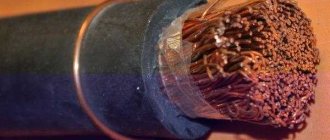
Wire - stranded or single-core conductor with tubular insulation or without insulation. This is simply a piece of copper or aluminum that can be protected from external influences.
Single-core and stranded wires
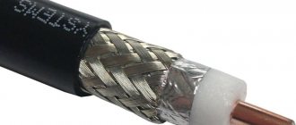
A cable is a system of insulated conductors that are united by one shell. That is, the main difference between a wire and a cable is insulation, protection from external influences. Essentially, all cable products are sheathed wires, twisted together and protected by several layers of different materials.
Cable
The differences between the products are described in the table below.
When the difference between cable and wire is obvious, the problem of product selection arises. Both products are classified according to different criteria. They should be selected based on the situation and place of use. The higher the product characteristics, the more expensive it is. Buying just the most expensive product is a waste of money, because its capabilities will not always be fully used. Sometimes the use of certain types of products is prohibited. For example, armored cables have low tensile strength and are therefore not used in overhead power lines. Product types
Wire classification
It is important to know the differences between wires of different types. This will help you choose the right products needed for repairing electronics and household appliances. Products are classified according to the number of cores:
Products are classified according to the number of cores:
- Monolithic wires. They have only one, whole vein. Such products, all other things being equal, have less resistance. Therefore, less interference is created during the transmission of information. Single-core wires are used when it is necessary to reduce the amount of noise at high frequencies. The disadvantage is low bending strength. Such products should not be bent many times.
- Stranded - consist of thin wires twisted together. Thanks to this, the mechanical strength of the products increases. If they break, it is not completely - only a few veins are broken, which slightly affects the characteristics.
Classification of cable products
An important characteristic of a cable is its insulation type. It is described in the product labeling. There are several types of shells:
- Protecting against mechanical damage - armor. It is made from steel strips or aluminum wire. The armor can be wound in one or more layers.
- Insulating - protects against penetration of moisture and dust. Made from polymers or elastomers. May have additional properties: oil, gasoline resistance, non-flammability, resistance to chemicals.
- Shielding protects against electromagnetic interference and stray currents. Available in aluminum sheathing, mesh braiding, or a combination of these materials. To increase tensile strength, the foil can be wound not in a continuous layer, but in a spiral. The mesh further increases the mechanical strength of the product.
All other things being equal, the more shells in a product, the more expensive it is, the more it weighs and the longer it lasts. A cable with double outer insulation can be used for at least 30 years, with a single outer insulation - 15 years. Therefore, in order to optimize financial and labor costs, suitable options are selected for each specific purpose.
When choosing, it is important to remember the following:
- In rooms with high air temperatures, for example in saunas and baths, special products in a heat-resistant shell are used.
- Heat resistance and non-flammability are different indicators. Therefore, products labeled with the letter “ng” are not necessarily suitable for rooms with extreme temperatures.
- Marking E120, E30, etc. means that the cable is capable of transmitting electricity even if it is exposed to fire. The designation number indicates the number of minutes that the product is capable of functioning. Such products are used in security systems.
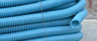
- For laying in the ground, you need a cable with a polyethylene sheath - the material resists decomposition well, which is what distinguishes it from PVC.
- A cable with a polyethylene sheath can be laid both openly and in the ground.
Creating an estimate for cable laying work is the task of professionals. There are many factors that need to be assessed before choosing a wire that suits the specifications. The wrong choice will at least lead to rapid failure of all wiring.
Couplings for armored cable
Armored cable is used very often when organizing power supply to equipment, since it is not afraid of mechanical shocks during installation and operation. For this type of cable products, a special type of cable couplings is used, which are marked with a capital or small letter “B”; some manufacturers may not mark their products in a different way. The cable coupling for armored cable faces the task of not only high-quality and reliable connection of cores with maximum sealing, but also restoration of impact resistance and mechanical protection of the area where the coupling is installed.
At the same time, cable couplings for armored power cables can be designed for standard 3, 4, or 5 cores, but also designed for installation on a single-core cable.
In order to ensure and restore resistance to mechanical damage, cable couplings for splicing, branching or terminating armored cables are equipped with metal “stockings” and grounding conductors. Here are several brands of products for armored cable 3 PKV(N) Tpb1, 3PSTb1, 4STp1 (universal).
Common mistakes when installing couplings
When installing connections, there are also typical mistakes that impair the performance of the structure.
Contaminated surfaces
The installer must take care of the cleanliness of the tools used and remove dirt in a timely manner. When working in holes or other “dirty” places, be sure to use film.
Violation of connector installation technology
If defects are found caused by inappropriate dimensions of the tube, they must be eliminated with a file and then sanded. The shavings remaining after grinding must be removed.
Uneven thickness of cuff insulation
This is a common case when using thick-walled heat-shrinkable cuffs. To avoid this problem, you need to evenly heat the area being treated. A tin reflector can also help with warming up.
Broken coupling tightness
This happens due to ignoring the sealant. The cause may also be damage to the insulation, in which case it is necessary to install a repair sleeve with an adhesive backing.
Important! The sealant should extend above the edges of the joint.
Air masses in couplings
As with end products, excess ions are produced in this case. When installing couplings, you must carefully follow the technology and take care to avoid common mistakes. In this case, the connection will be reliable and will last a long time.
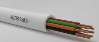
Control cable couplings
A control cable is often a multi-core cable product, each of the cores of which has its own insulation; its task is not to supply power supply voltage to electrical equipment, but to implement protection, signaling, and control circuits. This type of product also includes communication cables. In this case, lead couplings are used for communication cables, for example MS-20, which restores the protective sheath of the cable along with a single piece. All control cables are laid both indoors and outdoors and therefore very often require protection from mechanical damage. When marking cable couplings for a control cable, there are many, here is an example of the most common set - PSTk (connecting) or KKT (terminal), they are used for control cables with a number of cores from 4 to 37, the cross-section of which does not exceed 10 mm?.
Do you need cable couplings? Send your request and we will complete your order. We will select brands and give the best prices!
Send a request
Common mistakes in installing end couplings
All about cable installation
When installing coupling connections, craftsmen make typical mistakes.
Failure to maintain the required distance
It is especially important to monitor the interphase distance when working on high voltage lines. Ignoring this requirement threatens insulation breakdown. If the shield is too small, you will need to buy adapters.
Cross phase orientation
Do not allow different types of wiring to come into contact. This is fraught with field tension.
Tips with window for checking connection status
They can only be used indoors, securely protected from precipitation. If water gets into the window, the metal parts will begin to oxidize.
Installation of protective elements on the cores of outdoor couplings
These elements are required to prevent moisture from getting inside. The protective parts must also not be allowed to touch each other.
Air masses in the housing
This leads to the formation of ions in the gas space, which damages the protective part. During installation, it is necessary to seal the cracks with sealant.
Installation procedure for locking coupling
Installation begins with cutting the cable cores. First the armor and basic insulation are removed. Then the soaked paper is unwound. The paper insulation is removed until the prepared end of the conductor is given a conical shape. The exposed section of the wire should have a length equal to half the connecting sleeve.
Further activities are carried out according to step-by-step instructions:
- The prepared cable cores are connected to the locking device through connecting sleeves. Additionally, soldering of joints is carried out
Practical recommendation: There is an arrow on the frame of the locking device. It indicates the direction of inclination of the electrical route. This pointer must be taken into account when installing the device .
General view of switching the locking device through connecting sleeves
1 – cable, 2 – connecting sleeves, 3 – stoppers
- The joints are carefully insulated. For this, a special winding made of paper rolls and rolls is used.
- The switching unit is closed with two coupling halves (left and right), after which it is filled with cable mass through the holes
- Filling holes are closed with plugs
- Grounding is equipped: the shells and armored tapes of both cables are grounded with stranded copper wire. It is attached to the coupling body using bolted fasteners.
To protect the coupling from damage due to external influences, protective covers are used. They can be made of cast iron, steel or fiberglass.
Installation of locking couplings is carried out by a team (at least 2 people) staffed by electricians with qualifications of at least 5-6 categories.
Recommendations for selection
Choosing the right cable sleeves is extremely important. After all, during the connection all technical and mechanical characteristics must be maintained. It is also important that they meet all standards and last a long time. Therefore, we recommend watching this video, which explains in detail how to choose cable sleeves. We also recommend reading about how to make a wire branch correctly.
So we have discussed with you what types and types of cable couplings there are. This information will allow you to make the right choice and carry out high-quality installation work.
Design features of different types of couplings
The laying of power electrical routes may be accompanied by: joining cable sections of different lengths; branching the route into two or more lines; termination with connection of equipment or switching to overhead power lines; transition from one type of cable and wire products to another.
Such areas require reliable protection of the joints, therefore, different types of couplings indicated in the table are installed on such units. Their designs are noticeably different, but they all have the same purpose - to ensure the safe transmission of electricity. Some of them need to be considered in more detail.
Branch devices for connection
They apply:
- if it is necessary to connect a distribution conductor to the power route,
- for connecting stand-alone equipment
- creation of a separate power line.
Examples of metal branch couplings for one, two, three cable outlets
In addition to the options shown in the photo, there are T-shaped (at an angle of 90°), Y-shaped (with a 30° branch) and cross-shaped couplings. The principle of their installation is no different from those listed above.
End mast devices
End coupling KMSt for the transition from a three-core cable to an overhead power line.
They are used when transitioning from an insulated cable to overhead power lines on supports outside buildings or premises. These devices are designed for operation at temperatures as low as -40°C, which allows their use in most regions of the country.
The figure shows a coupling for a three-core cable, consisting of:
- top cover – 1;
- insulators – 2;
- rod pins – 3;
- grounding conductor – 4;
- necks – 5;
- main building – 6.
Such models are used for paper-insulated cables with a voltage of no more than 1 kV, and for their analogues with plastic insulation, PKMCH cast iron products are used.
Installation technology
Installation work must only be carried out by personnel who have completed special training courses. .
To perform installation work, a combined method is most often used, which consists of connecting the grounding wire to the cable insulation shells using springs with a stable pressure level, and then connecting with armor tapes. In the latter case, soldering of the connected elements is performed.
In most cases, the coupling package includes all the elements and consumables necessary for cable termination. They are usually packed in a separate corrugated box or plastic bag.
Before starting work, you should properly organize your workplace:
- place the required tools and accessories in close proximity;
- prepare the cable for cutting in advance;
- check that the cross-section of the conductors matches the set of heat-shrinkable couplings.
For high-quality installation, the elements undergoing heat shrinkage are heated to a temperature of 120-140°C. The heated part is subject to compression in the radial direction until it comes into direct contact with the surface of the cable sheath. Warming up is carried out using a blowtorch or a gas torch running on a propane-butane mixture. The burner flame should be made “soft”, moving slowly in the longitudinal direction, thereby ensuring uniform heating of the shrinking element.
Before heating the coupling, the flame from the gas burner should be directed to the side to check the operation of the device
Tip No. 2: The nozzle of a blowtorch or burner should be directed at an angle of 45° relative to the axis of the element, kept at a distance of 150-200 from the surface being heated.
The shrinking elements should fit as tightly as possible to the cable parts and should not have folds or wrinkles. After shrinking, excess glue should appear from under the edges of the sealing parts.
During the installation process, you should be guided by the general installation rules that exist for cables with a plastic or paper insulating layer up to 35 kV.
The coupling should be put into operation after it has cooled to at least 30-35°C and an acceptance check has been carried out:
- integrity of veins;
- high voltage testing;
- correct line phasing.
Installation of the cable termination must be carried out in accordance with accepted standards
Couplings based on the capacitor principle
To reduce manual winding, couplings are made based on the capacitor principle (Fig. 6). The main part of these couplings is a bakelite cylinder with paper winding, separated by metal spacers into a series of capacitors connected in series. In the center of the bakelite cylinder there is a metal ring which, when the capacitor sleeve is put in place, contacts the spring contact on the connecting clamp. A number of concentric spacers made of perforated metal foil are placed in the thickness of the paper winding. The ends of the gaskets are brought out to the bakelite cylinder using narrow foil strips placed between layers of paper. By appropriately selecting the distances between the spacers, it is possible to achieve a uniform distribution of stress along the surface of the bakelite cylinder.
Capacitor bushings are manufactured entirely at the factory, and their quality is controlled before being sent to the line, which avoids any kind of accidental defects. The installation of the capacitor coupling itself comes down to assembly operations. Couplings of this type are used for cables with a voltage of 110 kV. In various types of couplings, the lower quality of insulation and the worse shape of the electric field are compensated by increasing the thickness of the insulation compared to the thickness of the cable insulation. As a result, the outer diameter of the coupling is significantly larger than that of the cable.
Possible errors during installation and operation of the locking coupling
Neglect of grounding arrangement
If the cable insulation is broken, in the absence of grounding, there is a danger of electric shock to operating personnel. Considering the qualifications of electricians allowed to install cable fittings, such an error is unlikely, but cannot be completely ruled out.
Lack of maintenance
Electrical stop devices must be located in closed wells and subject to periodic inspections. During the inspection, humidity, ventilation, cleanliness, grounding condition, and cable fastenings are monitored. Identified deficiencies must be corrected in a timely manner.
Violation of the technology of filling the coupling with cable mass
The process of filling the device with mastic is very important. Do not allow the heated mass to boil or ignite (it becomes unsuitable for use). It is forbidden to mix the composition with a wooden object - moisture can get into the mixture from it. For these purposes, only metal stirrers are used.
Incorrect cable termination
When preparing the cores for connection, you cannot cut them to the same length in advance and strip the insulation. First, the ends must be bent into the desired configuration, suitable for the locking device, and only after that the excess length must be shortened. Otherwise, difficulties may arise during the switching process.
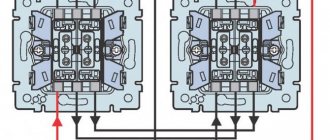
- Repair of a light switch in an apartment, a refrigerator with a regulator
- How to install a distribution box for electrical wiring in a brick, concrete wall
Technical requirements for couplings
If you carefully examine the cable connected by means of a coupling, you will notice that this part sequentially connects individual fragments of the cable fabric to each other. Because of this, the coupling for the power cable must also transmit electricity with minimal losses.
It is very important that the area of contact between the connecting element and the cable conductors corresponds to the size of the conductors, and ideally even be a little larger. Don't forget about the crimping force.
It must not only guarantee reliable contact from a mechanical point of view, but also the normal movement of electric current with minimal resistance.
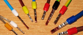
For the above reasons, the cores of any cable are secured using:
- tips, which are subsequently fixed with fasteners;
- special sleeves with additional fasteners and crimping.
End coupling
The insulating layer of the connecting element must:
- easy to transfer phase-to-phase voltage;
- have sufficient resistance to mechanical stress to protect the housing from breakdowns;
- resist the harmful effects of soil and groundwater for quite a long time.
Return to content
Choosing a method for connecting conductors
There are many ways to connect conductors. You need to choose a possible option taking into account the situation. So, if a temporary connection is necessary, you can simply twist or clamp the conductors between the bolt and nut. It is better to fix shaped or winding wires of large cross-section by welding or soldering.
Watch this video on YouTube
Cable connection sleeves or couplings are ideal for splicing cables. Connecting insulating clamps are well suited for fixing small cross-section wires and if you have the right size clamp. Terminal blocks are needed to assemble the circuit. Piercing and branching terminals are used to connect additional loads to an existing network.
Connection of stranded and solid conductors
This connection begins with selecting the cross-section of a stranded wire to a single-core one. A stranded conductor should not be smaller than the cross-section of a single conductor, otherwise it will burn out at the junction. They are fixed by soldering or welding, or by crimping when using cable sleeves.
When soldering, the wires are cleared of insulation, then the stranded wire is wound onto a single-core wire, and then soldering is performed. The soldering area is then protected with insulation. When crimping, the contact points are cleaned, a sleeve is put on, which is crimped with crimping pliers in several places.
Connecting wires with cross-sections of different diameters
Connecting wires with sections of different diameters is possible by calculating the current density in sections; if the density in sections is acceptable, then they can be connected by soldering, twisting, terminals or bolted connections. Connection technologies do not differ from the process of connecting wires with the same cross-section and were discussed above.
Connecting larger wires
This connection method is quite complicated with a large contact area. If the cross-section of rectangular wires is too large, fixation is only possible by welding and often cannot be done at home due to the need to heat the conductors to a high temperature. After welding the conductors, it is necessary to test the resulting contact.
When connecting stranded wires or large cross-section cables, you can use the cable connector already mentioned above.
Connecting broken wires in the wall
Often in everyday life situations arise when a breakdown of electrical wiring occurs in the wall. This often happens during renovation work. Initially, the electrical wiring must be de-energized and the plaster must be dismantled at the site of the repair work.
Afterwards, the insulation is stripped from each end of the damaged wire, and the ends are coated with molten lead-tin solder using a regular soldering iron. Immediately think through the insulation for the soldering area. It is good to use heat shrink tubing based on the size of the area being repaired. The tube is placed on one end of the conductors.
Next, a wire with a cross-section no smaller than the broken wire is selected, it is cut off and soldered first to one end of the wire, then to the other. At the same time, the length of the extended conductor should ensure the strength of the contacts. It shouldn't be too small or long. Finally, a tube is placed over the area, which, when heated with a hairdryer, tightly clasps the welded area.
Copper and aluminum connection
How to connect copper and aluminum wire is discussed in more detail in our article. Connecting opposite wires is possible using the bolted connection discussed earlier. However, most often fixation is carried out using copper-aluminum sleeves (CAS) for crimping. On the one hand, the sleeve is made of aluminum, on the second, copper. The aluminum side of the sleeve is larger because aluminum has a lower current density than copper. The sleeve is placed on the ends of the wires with the same metal and crimped with a press.
Methods for connecting SIP wires with different cables
Types of terminals for connecting wires
How can you connect the wires in a junction box?
How to properly connect copper and aluminum wires?
What types of terminal blocks are there?
How to use Wago terminal blocks to connect wires?
End
are sold by the company, for conductors with a cross section of 25-50, 70-120, 150-240 mm2, for voltages of 1, 6, 10.20, 35 kV. The complete set includes the use of bolted and pressed ends, as well as complete sealing using thermally fusible adhesive.
| Brand | Cable insulation | Cable brands | Availability of reservation |
| 3KVNTp-1 | paper | AABl, (A)SBl, (A)SBG, AAG, (A)SG, AABv, (A)SBShv, AAShv, (A)SShv, AAB2lShv, (A)SB2lShv, (A)SKl | with tape and wire armor, as well as without armor |
| 4KVNTp-1 |
Explanation of the designation 3KVNTp-1 25/50: 3 – for a cable with three cores K – end VN – internal and external installation T – heat-shrinkable p – glove included 1 – cable voltage 1 kV 25/50 – cable cross-section (mm2)
| Brand | Cable insulation | Cable brands | Availability of reservation |
| 1PKT-1 | plastic | (A)VVG (A)VVGz (A)PvVG NYM NYY | without reservation |
| 4PKTp-1 | |||
| 5PKTp-1 | |||
| 4PKTp(b)-1 | (A)VBBShv (A)PvBbShv (A)PvBbShp (A)VBV (A)VVB (A)VVBG (A)PvKShv (A)PvKShp | with tape and wire armor | |
| 5PKTp(b)-1 |
Explanation of the designation 4PKTp(b)-1: 4 - four cores P - plastic insulation K - end T - heat-shrinkable p - there is a glove b - with armor 1 - voltage 1 kV
Before choosing the type of cable sleeve, consider the following:
- conditions at the coupling installation site;
- operating voltage of the powered electrical installation;
- type of cable insulation;
- cross-section of cable cores and their number;
- the presence of armor on the cable, the type of shielding, and its other design features.
Couplings 1PSTp and 1P5STp are designed for joining cables with 3, 4 and 5 cores and plastic insulation. For cables with copper conductors 4PST-1 and 5PST-1 with 4 or 5 conductors, a heat-shrink sleeve is used. The armored cable uses a solderless grounding system. When making connections for pressing or bolting, you can use 5PST 1 or 4PST couplings.
2. To repair and connect unshielded copper flexible cables for voltages up to 1.2 kV, the types of couplings listed below are used.
Flood coupling - for connecting 3M™ Scotchcast™ 91 series cable, with installation without a torch flame. The cable connection remains flexible. When the coupling is equipped with a pair of rolls of Scotch 13 semiconducting tape, this filler coupling is suitable for connecting a shielded flexible cable 1140 V KGESH and its analogues.
Expert opinion
It-Technology, Electrical power and electronics specialist
Ask questions to the “Specialist for modernization of energy generation systems”
Cable couplings: description, purpose, classification | The fittings for power cables with elastomer are located in the inner part of the spiral cord and are installed in their proper place. Ask, I'm in touch!
Connecting sleeves
This part is necessary to ensure the most reliable contact between current-carrying elements. In stop couplings, sleeves are installed to connect the conductors to the stop rod. There are two most commonly used models:
- crimp - mounted by crimping or soldering (sometimes combined);
- screw – provide bolted connection of elements.
An example of a screw connection sleeve used in cable joints.
Crimping products are made from non-ferrous metals that combine good electrical conductivity, softness and strength.