What is a limit switch
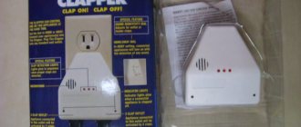
A limit switch is a limit switch, which is installed in the control system for generating a signal that gives permission for further operation of the circuit. It usually has several pairs of contacts (open and closed). But there are also contactless limit switches, which consist of an infrared LED and a photocell located opposite each other.
Device
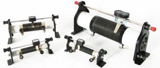
The limit switch consists of movable contact elements and fixed ones. It has a metal case in which the entire mechanism is installed. The switch structure is shown in the diagram below.
Mechanical limit switch (structural part)
The main parameter of limit switches is the free play of the switch rod, which, depending on the modification, is 0.5-2.7 mm. The operating stroke of switches is measured in millimeters. Therefore, the devices can be used using an additional lever, which is equipped with a small roller.
Principle of operation
Let's look at the principle of operation using the example of a car limit switch circuit. When any door acts mechanically on the roller of the movable rod, the contact closes, as a result of which the interior lamp lights up. The diodes on the electrical circuit are installed against reverse currents.
Schematic diagram of turning on the car lamp through limit switches
Application
Limit switches are used:
- in furniture products;
- in the automotive industry;
- in everyday life and household appliances;
- in production.
Connection diagram for a pass-through switch with 2 places
The circuit of a pass-through switch from two places is carried out using two pass-through single-key devices that work only in pairs. Each of them has one contact at the entry point, and a pair at the exit point.
Before connecting the pass-through switch, the connection diagram clearly displays all the stages; you should de-energize the room using the appropriate switch located in the control panel. After which it is necessary to additionally check that there is no voltage in all wires of the switch. To do this, use a special screwdriver.
To complete the work you will need: flat-head, Phillips and indicator screwdrivers, a knife, side cutters, a level, a tape measure and a hammer drill. To install switches and lay wires in the walls of the room, appropriate holes and grooves must be made in accordance with the device layout plan.
Unlike conventional switches, pass-through switches have not two, but three contacts and can switch the “phase” from the first contact to the second or third
Kinds
Limit switches are divided into the following types:
- mechanical;
- contactless;
- reed switches;
- ultrasonic;
- capacitive;
- sensory (optical);
- inductive.
Mechanical
Mechanical limit switches are the main type of switches in construction, as well as manufacturing and metallurgy. The presence of rubber seals on the contact group protects the devices from dust and dirt.
Contacts of mechanical limit switches can withstand current up to 16 amperes.
Mechanical switches are:
- push-button;
- lever;
- roller
Contactless
Contactless limit switches operate on a transistor switch, which has low resistance. The advantages of such devices include the absence of burning of contacts, as well as compactness.
Wireless switch
Ultrasonic
Ultrasonic circuit breakers are used as volume and motion sensors and are based on special quartz elements. The devices can withstand small loads in the circuit, such as from a curtain drive motor or low-voltage equipment.
Ultrasonic limit switch
Capacitive
Such switches operate in the event of a change in electrical capacitance created by man. When approaching the device, an electrical capacitance appears, which activates the multivibrator device located in the end switch. The closer a person comes, the greater the capacitance and the lower the pulse frequency. The basis of the mechanism is the capacitor plate.
The video below discusses capacitive limit switches. Filmed by chipdip channel.
Touch (optical)
The touch switch device has an infrared LED and a phototransistor. The diode, controlling the supplied pulse, allows the circuit to open the phototransistor. Such devices can be widely used on CNC.
Inductive
Inductive limit switches operate within a specified range of the electromagnetic field. The sensor, which has left the magnetic field zone, sends a pulse to turn on the device.
How to connect a limit switch
Before connecting the wires of devices, it is necessary to turn off the electricity by making a switch in the panel. Limit switch installation requires careful adjustment of the response.
To install and connect the device, you need to fix the door using four self-tapping screws so that when closed it presses on the limit switch key, and when open the button is released. Connect the electrical circuits of the switch through the terminal block to a current of 220 V.
The limit switch in the electrical circuit should be the last element before the supply wire.
For the front door
The limit switch on the front door is designed to ensure the functioning of the alarm system and activate the light in the apartment. It is more advisable to install contactless sensors, since they take up little space and are quite reliable in operation.
Before installation, the position of the door and the limit switch should be taken into account. To connect the electrical circuit device, it must be done on a fireproof base for fire protection purposes. Installation and adjustment of the switch should be done with a certified tool.
For wardrobe
The purpose of installing limit switches is to provide automatic lighting when the door is opened. First you need to lay electrical wiring to the cabinet. At the ends of sliding doors, it is required to install a door mechanical switch with a voltage of 220 volts. All wires must be laid in protected trays. Then the installation of the lamp and end strips are marked. After installation, the wires are connected and the operation of the limit switches is adjusted.
For sliding doors
For sliding doors, the installation of a limit switch is similar to that for furniture, but an ultrasonic sensor should be used.
For swing doors
For swing doors you need to use a mechanical push-button switch type 4313WD. Wires to the installation site are laid in trays. Setting up the operation of the switch with your own hands must be done carefully without damaging it, since the working stroke of the rod is 3.5 mm.
For gates
Roller mechanical limit switches are used to automatically open and close gates. Installation is possible only on sliding gates, since they have less play in the mechanical part than swing gates. At the ends of the gate it is necessary to install end gates, which will be connected to the opening drive motor and to the starter.
When installing switch devices on gates, the conductors are supplied to the electric motor in a corrugated pipe, and the switch is installed in a moisture-resistant housing.
For auto
The installation of limit switches in the car is necessary for the functioning of the alarm and lighting. A simple push-button switch is used on the hood and trunk doors. For interior doors - contactless. After connecting the limit switches for the car, you should adjust the sensitivity of the security system.
Loading …
Hood switch
What is a hood switch? This is still the same rod switch, except that the rod is longer than in the doors or trunk. Since the hood end is located on the front frame, the distance to the hood is quite large, which is why it is necessary to use a long rod.
This is the most rarely installed standard limit switch. On cars without a standard alarm system, it can be used by the factory only for the engine compartment lamp, which is offhand only remembered from the VAZ “eighth” family. Therefore, these alarm switches have to be connected independently, and therefore at least one limit switch is always included in the security systems.
But it also happens the other way around: for example, on Renault Megane 3 and Fluence for the Russian market it is standard in all trim levels except the minimum one, and is even built into the hood latch. And there are even wires going to it... but it’s impossible to find them in the cabin, because they remain under the hood, not connected anywhere. When installing an alarm, of course, you don’t have to install your limit switch, but you still have to run the wires under the hood.
This alarm switch will be the most problematic: water and dirt will get under the edge of the hood, causing corrosion, or failure of the switch, or false alarms. Therefore, you need to carefully select the location, if possible installing the limit switch in the cleanest available location.
Video “Design of limit switches”
The video shows the design of limit switches. Filmed by chipdip channel.
Limit switches, end caps, limit or limit switches are the name given to a device for limiting the movement of a mechanism. They have special requirements for setting up the response. If used incorrectly (positioned in the electrical circuit), an accident may occur - the moving mechanism may break.
According to the principle of operation, it resembles a regular switch, only it does not work manually by directly pressing a key at will, but in special situations - if necessary, prevent further movement, limit it within acceptable limits.
How to deceive a reed switch
The huge number of clients that SpetsLab currently has cannot but bear fruit. Constant feedback and exchange of experience add practical knowledge. The latest news did not go unnoticed. A recent client shared his method for using the background detector. By the way, he came to us specifically for the analytical system - other methods of self-preservation were already dead for him.
His supermarket, small by today's standards, mainly of food products, has 82 doors leading to various corridors and exits. Its alarm system is made with the latest technology and has one of the most expensive security systems. The project was carried out by a very well-known and therefore experienced company.
Design
Looking at the photo of the limit switch, you can see that it consists of 2 or 3 main parts:
- Dielectric or current-conducting housing (depending on purpose and design).
- A moving mechanical part that responds to pressure. Contactless and electromagnetic ones do not have it. This part is missing from their design.
- A group of normally open/closed contacts that control movement or provide a signal.
It resembles a box of small or even miniature sizes with a moving part in the form of a button, wheel or lever.
Device and principle of operation
Structurally, a single-key switch consists of four main parts:
- base (metal, less often plastic);
- a working mechanism consisting of a contact group, clamps (for connecting electrical wires) and fastening elements;
- keys;
- protective decorative element (frame or case).
The operating principle of any single-key switch is extremely simple:
- In the “on” position, the elements of the contact group are closed and voltage is supplied to the lighting device. It starts to function.
- And vice versa, in the “off” position the contacts are disconnected, a “break” occurs in the “phase” circuit, and the lamp goes out.
Principle of operation
The limit switch works in different ways: to supply or cut off voltage. This can be either a direct mechanical effect - push, touch, pressing, or the effect of electromagnetic fields, ultrasound or infrared radiation on special elements included in the design of the switch.
Sensory ones, for example, react to an object entering the radiation spectrum of rays, capacitive ones - to the approach of a person, mechanical ones - only to direct physical impact.
Regardless of the functional features, a group of contacts that control the required range of motion is always activated.
At the same time, it is important to correctly configure and install the limit switch so that it does not start prematurely, does not miss a signal, or breaks when a working mechanism “runs into” it.
Pros and cons of proximity switches
A contactless switch is an alternative and at the same time a special case of a touch switch. It works on infrared radiation and allows you to turn on the backlight with a wave of your hand, i.e. without contact. The design is based on 2 elements: an emitter and a receiver. The switch reacts when any object appears within 2-7 cm of it. Such models are used in places where an important condition is the absence of hand contact with surfaces and objects.
When choosing contactless switches, it is necessary to take into account the profile material to which the LED strip will be attached. If it is aluminum, then you should avoid options with the chip located at the bottom and the power switch at the top. Such a switch cannot be attached to the bottom surface of an aluminum profile. It is only suitable for plastic. In the case of aluminum, you need to choose switches with a flat and smooth bottom base.
Another disadvantage of proximity switches is their width. Usually it is a couple of millimeters larger than the LED strip itself. Other important features:
- To operate the switch, you need to cut a window in the diffuser.
- The mode automatically turns off the backlight when the voltage suddenly disappears, and turns on when it appears. This is not typical for all switches, but it is worth clarifying this nuance before purchasing.
Thus, contactless switches have one serious drawback - lightning-fast reaction, so it is important to choose the right installation location
Classification
Limit switches are divided into types and groups. The requirements for their type and configuration are determined by the scope of their application and purpose.
There are such groups of limit switches:
- Mechanical or contact. Triggering occurs when there is direct action on a pin, button, wheel or lever. A control or warning signal is issued. These also include microswitches. Their serious drawback is burning and sticking of contacts when switched on and off repeatedly. For long-term use, without frequent repairs, their design includes arc arrester chambers.
- Pneumatic. They react to pressure in the system and stop the supply of air or any gas.
- Reed switches (electromagnetic). Activated when approaching a certain point in space. Tuned to a magnet included in the moving mechanism.
- Automotive. Used in signaling and lighting circuits. Can be classified as mechanical, since the operating principle is the same.
- Contactless. They are triggered when any object approaches a certain area.
- Spindle. They limit the movement of the mechanism and are often used as a limit switch. Can be used where the shaft rotates at low speed.
Brief characteristics of some subspecies
The design of mechanical limit switches is determined by their scope of application. Most often this is:
- Construction;
- Mechanical engineering;
- Metallurgy.
- Various production purposes requiring automatic control.
They are mainly manufactured in the following types:
- Roller
- Lever;
- Float;
- Push-button.
Microswitches
Microswitches are a type of mechanical limit switches. They are mainly used in electronics and household appliances. But you can use them effectively at home: place them on the door so that when you open it, the light comes on or the hood turns on.
They require special care in setting up the response, since the stroke of their moving part is calculated in millimeters.
Proximity switches
Contactless switches are a more advanced device, the operation of which involves transistor switches with low resistance. When the electrical circuit breaks, the contacts do not burn.
Contactless switches have their own variety:
Ultrasonic
Used as volume and motion sensors. The design contains special sound quartz elements.
Capacitive
React to the approach of a human body. Based on interaction with him.
Touch (optical)
The design includes a special infrared LED and phototransistor. Works in any lighting. When the LED beam is interrupted, the photocell is triggered, and the working mechanism is turned off and on.
Inductive
Reacts to electromagnetic fields when approaching or moving away. Triggers when the settings are satisfied: the mechanism enters the impact zone or goes beyond it.
Based on contactless communication devices, various useful, highly sensitive sensors are manufactured, which are widely used in the process of automation of production processes. Control and dosage of liquid and bulk materials is the main area of their application.
It is important before directly installing the limit switch (regardless of its type) to turn off the voltage and de-energize the power circuit. The connection diagram itself is usually drawn on the device body and will not cause any difficulties.
To understand where the limit switch needs to be installed, you need to carefully study the features of the mechanism whose operation needs to be controlled.
Before purchasing a device and all its components, you should definitely consult with a specialist to understand which type or model is best suited for specific purposes.
In order not to overpay or buy something that is not needed, it is important to understand why the limit switch is purchased, what it will limit, which device to turn on or off. The right choice and proper connection are the key to long-term work!
Door switches: where they are located, connection, checking
Initially, limit switches were installed on the doors to automatically turn on the interior lamp. Their connection scheme was the simplest - everything was connected in parallel, that is, it did not matter which door was open. In budget car configurations, only the driver's door switch was often installed.
Video: Problems with limit switches in Lada Vesta, Grant and Kalina
The weak link of such limit switches was the need to place them in an extremely inconvenient place: the protruding part of the metal sheet of the door in the lower corner pressed on them; less often, designers managed to place the limit switch higher. Because of this, they often failed even despite the sealing cap on the outside. For a car with an alarm, this meant randomly triggering the alarm at the wrong time, or, just as bad, being able to open the door without setting off the alarm.
Subsequently, the connection diagrams for limit switches in doors became more complex - initially to indicate a specific open door on primitive on-board computers. Here, each door had its own signal wire, which complicated the installation of alarms: since the limit switches need to be connected to the only input of the central unit, an attempt to connect it with all the limit switches immediately leads to a violation of the display on the on-board computer screen (shows all doors open at the same time). Because of this, it is necessary to use diode isolation, which allows you to logically combine the outputs of the limit switches without disturbing the operation of the computer.
It works simply: since the diode conducts current only in one direction, when any of the limit switches is closed, the alarm output is connected to ground in any case, but the pressed one is connected to the rest of the limit switch wires through a back-to-back pair of diodes that do not pass current.
The solution to the problem with the reliability of limit switches turned out to be quite simple. It has long become the norm that the door end is located in the lock mechanism itself, that is, it is raised high and well protected from water, if, of course, the glass seal is in good working order. Note that the very principle of operation of the door limit switch has changed. If the door limit switch is installed in the slam, then it is triggered at a certain position of the door, closing the contacts when it begins to open.
If the door switch is in the lock, it is triggered by moving the locking mechanism: often (but not necessarily) it is enough to lift the handle without opening the door itself to close the contacts. This, by the way, makes installing alarms more convenient: you can leave the door open during operation by clicking the lock pawl with a screwdriver, and the alarm will no longer “see” the door open.
It is so good, for example, to adjust the shock sensor by arming the car with the door open, and not repeating the cycle “closed - armed - struck - disarmed - opened the door - changed the setting” for each adjustment.
On modern cars, the driver's door switch has received one more function - it is usually responsible for “falling asleep” and “waking up” of the on-board electronics. For this reason, on alarm systems with auto-start, it is necessary to connect a circuit simulating the opening of the driver’s door: the on-board controller at the end of the auto-start cycle will “see” that after turning off the ignition the door opened and closed, and will normally switch the car into a low-power mode.
In this case, a short-term “ground” pulse often appears on the limit switch wire, which, with a conventional diode isolation circuit, triggers an alarm for opening the door some time after arming. To avoid this, the diode decoupling circuit is complicated.
The difference with the previous diagram is that the diodes also cut into the standard wiring, and the alarm is connected between the diode and the limit switch. In this case, when the limit switch is closed, ground comes to both the standard vehicle on-board circuit control unit and the alarm system. But, when the controller creates a “ground” pulse in the standard wiring, the alarm input is blocked by back-to-back diodes, and no alarm is triggered.
It is important to understand that the duration of such pulses is very short, and the alarm can work correctly even when decoupled with one diode per line: for example, Sherkhans are less sensitive than StarLine, according to the author’s experience. But sometimes random operations are possible, and this is often associated with owner problems, when the limit switches are absolutely in good working order, but the car still sometimes “screams on its own.”
To check the door switches , press them with your finger (if the switch is located in the door lock) or with a suitable object (for example, a screwdriver) and latch the door lock pawl. As an indicator, you can use either the interior lamp, set to the “switch on when the door is opened” position, or the on-board computer screen, if it has an opening indication. Having discovered that the limit switch does not work in some door, then rule out a wiring fault.
The easiest way to do this, of course, is if the limit switch is in the tail: pry up the plastic retainer and pull it towards you. If the limit switch is in the lock, then you will have to disassemble the door. To check the wiring, simply remove the connector from the limit switch and close the contacts in the block. If the opening indication worked as expected, then the door switch needs to be replaced, otherwise the problem is clearly not in it. If the alarm system is installed on a budget car with a minimum configuration, where there is only one limit switch or none at all, you have to connect them yourself. The biggest mistake here is the use of cheap limit switches for alarms, which should not be used.
Their reliability is extremely low, and for fastening they require the use of a self-tapping screw - this is an extra hole in the body, and even in a place that is potentially dangerous in terms of corrosion. The ideal option is to install standard limit switches from more expensive trim levels, since for the purpose of unification, installation holes for them are available in all versions of the car.