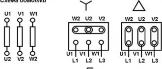
Star and delta are the main types of connections in three-phase current installations. Each scheme has properties unique to it, and it is important to apply or combine it correctly.
This review is aimed primarily at a wide audience who may not know the terminology, calculation features, vectors and other highly specialized information. And there is no point in it if there is no understanding. And retransmission of textbooks and other electrical literature without proper explanation is a road to nowhere. Therefore, we will try, in as simple terms as possible, to consider the main features of using star and triangle schemes.
Where is the star-delta connection used?
If we analyze the search results, it turns out that most often people are looking for information about star and delta circuits in the context of connecting an asynchronous three-phase motor. Naturally, at the everyday level, this is the most common case of using one or another scheme. And, naturally, we will consider the features of using this or that circuit when connecting a three-phase consumer. But first I would like to highlight the equally important use of star and delta combinations in the distribution of electricity from a power plant through transformers to consumers.
It would seem, why do we need to know the features of electricity transformation? However, the topic is quite interesting, complex and poorly covered. After all, we all know that electricity is generated at a power station by generators, transformed and supplied to our homes. And if with the last link everything is more or less clear. The information about the first two links is often vague, sometimes contradictory or difficult to understand. Therefore, let's consider a simple explanation of the transformation of electricity through star-delta, triangle-star combinations. But first we give definitions of these connection methods.
Star, triangle - definitions
Depending on the method of connecting the generator windings and the load, a distinction is made between star and delta connections. Each phase winding of the generator has two terminals, which are conventionally called the beginning and the end. The beginning of the winding is taken to be the terminal to which the positive EMF is directed.
When connected by a star, the ends of all phases of the generator are connected into one node. It is called the neutral node or neutral point. The neutral points of the generator and the load are often connected with a neutral (neutral) wire. The remaining wires connecting the generator windings to the receiver are called linear.
In a delta connection, the beginning of one phase winding is connected to the end of the next so that the three windings form a closed triangle.
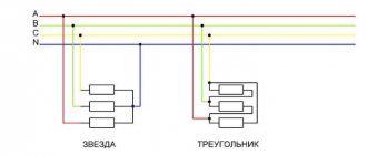
In practice, various combinations of generator and load phase connections are used: star-star, star-delta, delta-delta. There are also combinations with a zigzag, but we will not touch on them in this review.
Voltages and currents in the generator and load phases are called phase and are designated Uph, Ia. The voltages between linear wires and the currents in them are called linear and are designated Ul, Il. From the diagrams discussed above it follows that when connected by a star, Il = Iph, and when connected by a triangle, Ul = Uph.
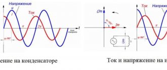
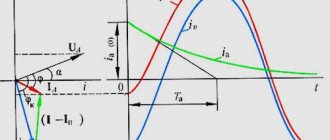
If the windings of a 220 Volt power source are connected in a triangle, the phase and line voltages are respectively equal to 220 Volts. The relationships between linear and phase voltages when connected by a star are already different. You can find them using a vector diagram or by analyzing sinusoids of three phases, as shown in the following video:
Calculation of linear voltage by vectors comes down to the analysis of an isosceles triangle with base angles of 30°. You can also calculate the difference between vectors using complex numbers. We will not dwell on these methods in detail. Let us only note the consequence - when connected by a star, the linear voltage Uл = √3 × Uф (380 = √3 × 220).
Unbalanced load when connecting receivers in a triangle
In the case of asymmetrical phase resistance, as in the case of a star connection, to connect to the network, electrical receivers are divided into three groups of approximately equal power. Each group is connected to two phase wires, which have differences in phase:
Within each group, the receivers are connected in parallel.
After replacing the resistance of several receivers in one phase with one equivalent one, we obtain the following circuit:
The shift angles between voltage and current, power and phase currents can be found from formula (2). In the case of an asymmetrical load (in our case, the diagram is above), the phase powers, currents, and shift angles (cos φ) will not be equal. The vector diagram for the case when phase ab has an active load, bc is active-inductive, ca is active-capacitive, is shown below:
To determine the total power of all phases, you need to use the expression:
Example
Given an asymmetrical electrical circuit, connected according to the diagram above, with the parameters: UЛ = 220 V, rab = 40 Ohm, xLbc = 10 Ohm, rbс = 17.3 Ohm, xca = 5 Ohm, rCca = 8.65 Ohm. It is necessary to determine linear and phase currents, as well as powers.
Solution
Using the expression to determine complex values, we get:
Complex values of phase impedances: Zab = 40 Ohm, Zbс = 17.3 + j10 Ohm, Zbс = 8.65 – j5 Ohm.
Complex and effective values of linear and phase currents:
You can carry out calculations longer without resorting to a complex method:
Total active and reactive powers:
Shift angles between currents and voltages:
The vector diagram for an asymmetrical triangle was given above.
Voltage transformation using star and delta combinations
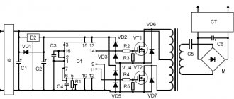
With a power plant generator power of 500 MW and a voltage of 10 kV, the current in the wires will be 50 thousand amperes. When transmitting over long distances, wires, as a load, have significant resistance. Consequently, most of the current will be wasted heating the wires. To minimize losses during the transportation of electricity, the only effective way is to increase the voltage, which will lead to a decrease in current. But without distribution transformers (step-up and step-down) this cannot be done.
Now we will not dwell in detail on the principle of operation of the transformer. We are more interested in the peculiarity of connecting its windings with a star or triangle.
We will simulate in the Multisim program. Let's start drawing the circuit with a three-phase generator, the windings of which are connected in a star. We ground the connection point of the windings. At this stage, we note that despite the fact that generators at power plants generate voltages of thousands of volts and transform it all the way by increasing and decreasing, we will take a generator that generates 220 volts that we understand. Also, you should not compare the diagrams shown here with a real system, since the path from the power plant to the consumer is much more complicated.
Now let's add a transformer. More precisely, we will assemble it from three transformers in such a way that the primary winding is connected in a star, and the secondary in a triangle. We will not increase the voltage, but let’s see what transformation occurred when connecting the transformer windings according to the star-delta circuit.
When switching from star to delta windings of generators or secondary windings of transformers, the following occurs:
- The network voltage decreases by 1.73 times. In our case, the line voltage is reduced from 380 to 220 Volts.
- The power of the generator and transformer remains the same. And all because the voltage of each phase winding remains the same and the current in each phase winding is the same, although the current in the linear wires increases by 1.73 times. We will show this a little later, when we close the circuit through consumers. But first, let’s add another transformer with a delta-star circuit to our circuit and connect the load to it.
When switching generator windings or secondary windings of transformers from delta to star, the opposite phenomena occur:
- The line voltage in the network increases by 1.73 times. In our case, from 220 to 380 Volts.
- The currents in the phase windings remain the same, the currents in the linear wires decrease by 1.73 times.
Now let's understand the reasons for transformations in simple words without using vectors. To do this, consider the movement of free electrons in a circuit and analyze the potentials at a specific moment in time. You probably won’t see this explanation anywhere, but it is perhaps the easiest to understand.
The first thing in our chain is the generator. Simply put, it has three stator windings offset by 120° relative to each other. When the rotor rotates, a periodically varying EMF with an amplitude of approximately 312 Volts appears in the stator windings. This is the amplitude value of the voltage, and we will not move from it to the actual voltage. At the moment when the voltage at one of the generator terminals is +312 Volts, at the other two -156 Volts. Let's stop at this point and move on to the voltages of the transformer windings.
The voltages at the considered moment in time both on the primary winding and on the secondary winding correspond to the +312, -156, -156 Volts highlighted above. So why do the currents in the linear wires extending from the triangle windings increase by the root of three times, and the linear voltage decreases by the same amount? The whole secret is in particular the connection of the windings in a triangle, and then we will clearly demonstrate this by moving to a more simplified diagram.
Since in a delta connection the beginning of one phase winding is connected to the end of the next, the winding voltage of +312 Volts will be distributed between the winding with a voltage of -156 Volts and the output. As a result, the output of the winding with a voltage of +312 Volts will be +156 Volts, and the output of the winding with a voltage of -156 Volts will be 0 Volts. We are left with the third winding with a voltage of -156 Volts, and at its output it will remain -156 Volts. As a result, we get the output voltage at the moment we considered +156, -156, 0 Volts (and it was +312, -156, -156 Volts).
The resulting linear voltage is +156-(-156) = +312 Volts (this is the amplitude value). After converting to the actual value, we get 220 Volts. Why is 0 Volt not considered? You need to understand that the frequency of 50 Hertz has not disappeared anywhere, and where there is zero, in a moment it will be +156, in another moment -156. And such alternation will be constant. But let's return to the moment in time in question. We sorted out the drop in line voltage from 380 to 220 Volts. Now let's explain why the current increased. It's actually simple. Having reduced the voltage to transmit the initial power, we need to proportionally increase the current.
When moving from a triangle to a star, a reverse transformation occurs. To see this in the diagram, you need to find the winding voltages on the second transformer connected in a delta-star circuit. Having calculated the potential differences between the beginnings and ends of the windings, we will return to the original +312, -156, -156 Volts.
In order to confirm our calculations and clearly see the phase shift, let’s return to the Multisim program and connect an oscilloscope to the phases.
A phase coming from a generator with star windings is connected to pin A of the xsc1 oscilloscope. The remaining three pins of this oscilloscope are connected to the phases after the star-delta transformation. As you can see, after the transformation of the sinusoid, the phase shifted by 30°. And if you move the cursor to the amplitude value ≈ +310 Volts of channel A, then on the remaining channels related to the phases after transformation there will be approximately +155, -155 and 0 Volts. That is, the oscilloscope showed the same thing that we calculated earlier.
To analyze the reverse transformation, we connected the same phase from the generator to pin A of the xsc2 oscilloscope, and the remaining pins were connected to the phases after the delta-star transformer. As a result, the shift disappeared and the phase sinusoids returned to their amplitudes of 312 Volts. True, if you pay attention, the sinusoids of the phases after the transformation were mirrored in relation to the sinusoids of the phases after the generator. In order to reflect back, it is enough to swap the terminals of the windings according to the star circuit.
As you can see, by using various combinations of “star” and “triangle” with the same inductances of the primary and secondary windings, you can move from one voltage to another. And in order to see all this clearly, it is enough to use a program for modeling digital and analog electronic circuits. In our case, the simulation was carried out in the Multisim program environment.
Receiver delta connection
In this case, the receiver terminals a,b,c are connected to the phase terminals of the electrical energy source A,B,C (figure). Thus, a symmetrical system of linear voltages of a three-phase source of electrical energy is applied to the phases of the receiver.
Diagram of a three-phase electrical circuit when connecting the receiver in a triangle
In linear wires A−a, B−b, C−c linear currents flow: IA, IB, IC
.
Phase currents Iab, Ibc, Ica
, determined by Ohm’s law in complex form:
Linear currents with known phase currents are found according to Kirchhoff’s first law in complex form:
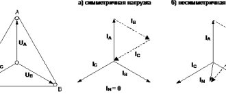
With a symmetrical receiver (Za=Zb=Zc=Zph), the systems of phase Iph and linear Il currents are symmetrical, and the modules of phase and linear currents are in the ratio:
I L =√3 I F
Vector diagram of currents and voltages of an electrical circuit when connecting a resistive receiver (the phase shift between the phase voltages and phase currents of the receiver is zero φ=0). triangle for the case of symmetrical (a) and asymmetrical (b) loads.
Three-phase circuit power.
As in a single-phase linear circuit of sinusoidal current, in a three-phase linear circuit there can be three types of power: a) active -P; b) reactive -Q; c) full -S. The active power of a three-phase electrical circuit is the sum of the active powers of all phases of electrical energy sources or all phases of the receiver. Three-phase electrical circuit with a symmetrical receiver . In an electrical circuit with a symmetrical receiver, for any scheme of their connections, for each of the phases of the receiver we have: Рф=UфIфcosφ
, where is the phase shift angle between phase voltage Uph and current Iph.
Active power of the entire electrical circuit: Р=3Рф =3Uф·Iф·cosφ
or
Р=√ 3УЛ I Л cosφ
.
Reactive power for each of the receiver phases: Qф=UфIф sinφ
Reactive power of the entire circuit: Q=3 Uф Iф sinφ or Q=√3⋅Uл Iл sinφ.
For total power in the case of a symmetrical receiver we have: S = 3UФ IФ =√ 3UЛ IP.
Power factor cosφ=P/S.
The power factor shows what portion of electrical energy is irreversibly converted into other forms (used to perform useful work). AC machines, transformers and many other devices are designed for a given full power. At low cosφ
they turn out to be loaded in terms of current, but underutilized in terms of active power.
To increase cosφ,
various measures are used, which come down to either reducing reactive power or compensating reactive inductive power with reactive capacitive power.
Measurement of active power in three-phase circuits.
1.When connecting the phases of the star-shaped receiver with the neutral wire, the three-wattmeter method is used.
2.When connecting the receiver phases in a star shape in the absence of a neutral wire, the two-wattmeter method is used.
3.When connecting the receiver phases in a triangle shape, the two-wattmeter method is used.
Rotating magnetic field
This phenomenon was discovered in 1882 by the Serbian engineer N. Tesla and a little later by the Italian physicist G. Ferraris. One of the main advantages of three-phase current is the creation of a rotating magnetic flux. This phenomenon underlies the operating principle of AC motors. Let's see how it turns out
rotating magnetic field of three-phase current. Let currents flow through three stationary windings
The graphs of these currents are shown in Fig. A
Rice. A
The windings are shown in a simplified manner, each in the form of one turn. The direction of the current from the beginning of the phase to its end is assumed to be positive.
For example, at time 0, the current in phase A is zero, the current in phase C has a positive direction and is therefore represented by a cross, and the current in phase B has a negative direction and is depicted by a dot. These currents in the windings create magnetic fluxes:
the direction of which is determined by the gimlet rule. The direction of the total magnetic flux for times 0, 1,2, 3 is shown in Fig. 12.20 straight arrows. As you can see, the magnetic field of the stationary coils rotates clockwise and makes one revolution during the period. Thus, the magnetic flux rotates at the same speed with which the currents in the phases change. Moreover, the phase difference for two-phase systems should be 90°, and for three-phase systems 120°. The amount of rotating magnetic flux remains constant. To change the direction of rotation of the magnetic field, it is enough to swap the clamps of the two phases.
A field whose magnetic induction vector, without changing in magnitude, rotates at a constant angular velocity is called a rotating magnetic field. The rotation speed of the magnetic field n is determined from the expression
where / is the frequency of alternating current; p is the number of pairs of poles of the electric machine