Microwave technology for quickly heating food in normal operation requires compliance with certain safety rules, which are set out in the operating instructions. When equipment breaks down and an unskilled worker undertakes repairs, the risks of electrical injury from high-voltage voltage or deterioration of health due to high-frequency radiation increase sharply.
A DIYer who knows how to measure the voltage level of an electrical circuit can safely perform a DIY microwave oven repair. But to do this, you must first familiarize yourself with its design, dangerous components, safety rules when troubleshooting, and pay special attention to inspections and testing.
The structure of a microwave oven is not as complicated as it seems at first glance. Breakdowns occur for two reasons:
- mechanical wear or contamination of parts;
- damage to electrical circuit components.
Let's look at them in more detail.
- Timer
- Kinematics of the working chamber
- Microwave pulse generation circuit
- Magnetron connection
- Magnetron damage
- How to check the magnetron power transformer
- Cooking chamber and wave guide
Device and principle of operation
We will look at this issue superficially so as not to deviate from the main topic. The information will be simplified as much as possible, since not all home craftsmen have deep knowledge of electrical engineering. Let's start with a description and purpose of the main structural elements, they are presented below in the figure.
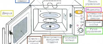
Rice. 1. Microwave device
Designations:
- Door latches serve both to secure the door and to lock the door in the open position.
- A rotating tray on which dielectric cookware is placed.
- A separator equipped with rollers that drives the pallet.
- Drive rotating the separator.
- The backlight turns on depending on the operating mode.
- Ventilation (usually forced).
- A magnetron is a microwave radiation generator; in fact, it is the main structural element. You can find out how it works and the principle of its operation by reading the article on our website dedicated to this issue.
- The waveguide ensures the movement of microwave waves to the microwave chamber. It is a hollow metal pipe of rectangular cross-section.
- High voltage diode.
- Capacitor.
- Waveguide power supply circuit transformer and control circuit.
- Control block.
We will not provide a complete schematic diagram of the device, since they can differ greatly in different models of microwave ovens. In our case, the magnetron power circuit will be sufficient. As a rule, it has a standard structure.
Typical magnetron power circuit diagram
Let us briefly describe the operating principle of the above circuit. Power to the primary winding of the transformer (I) comes from an external control circuit that regulates the power and duration of microwave radiation. One of the secondary windings (II) supplies voltage to the magnetron filament. Winding II is made of 2-4 turns of thick wire, since the current in the filament circuit can reach 10.0 A at a voltage of about 3 volts.
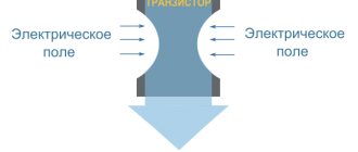
Another secondary winding (III), which supplies a high voltage level (up to 3.0 kV), is usually called anode. As can be seen from the figure, in this circuit, a rectifier and voltage multiplier are built on the basis of a high-voltage diode (VD1) and a capacitor (C1). In this case, VD1 is turned on so that the opening occurs at a positive half-cycle, as a result the capacitor begins to charge. When the negative half-cycle begins, diode VD1 closes and voltage is supplied to magnetron M1 together with the charge accumulated on the capacitor. This leads to a doubling of the voltage and the formation of an electric field of the required intensity in the magnetron.
Resistance R1 in this case is necessary for discharge C1. Typically, this resistor is located in the capacitor housing. As for VD2, it provides protection in the event of an increase in voltage across capacitor C1 or a short circuit occurs in magnetron M1.
Service Mechanisms
Typically, a swarm of units is connected in series in a microwave oven. Now we are discussing secondary mechanisms: fan motors, table motors, quartz grill lamps, backlight bulb. This is done to reduce the number of wires. Design changes simplify microwave repair to the maximum. Result: burnout of one element blocks the operation of the furnace. The magnetron threshes, as does the start relay. The noted effect is a characteristic sign of the cause hidden in the auxiliary mechanism. An equivalent result if the third relay breaks, breaking the power circuit in the normal state (the door is open and the button is released). but if a relay is powered from it (as stated above), microwave oscillations will not be generated.
The above diagram is typical for microwave ovens; we believe there are other designs. Just take note of the designers' imaginations. The elements inside the microwave oven are powered by 220 volts. There are no other special sources inside. Models stuffed with electronics stand out sharply. An inverter requires a number of voltages to operate.
I would like to note that in microwave ovens with hybrid modes you can test almost 100% of the component parts of the product separately. Study the design of the programmer. It is convenient to shine the light on the grill while the magnetron is turned off. Beginners are perplexed: how to regulate the power of the grill. We believe that the share of this component of the microwave oven is made up of energy not consumed by the magnetron. The microwave operates longer, leaving less time for other components of the electrical circuit.
Now let’s say a few words regarding the occurrence of a fire inside a microwave oven: thunder and lightning strike. At the output of the waveguide that transmits microwave energy to the compartment, there is a mica filter. Visually dense fabric, reminiscent of building insulation. The surface must be clean and dry. Otherwise, thunder and lightning will arise without difficulty. Fat contributes to the breakdown of the insulation, resulting in a discharge inside. Be foolish enough to put a plug in the compartment - lightning will easily pierce the enamel coating. A black spot will remain; in the worst case, the wall will burn through.
The main types of malfunctions are listed, the design is described - we hope that readers will play the presentation.
Please note that microwave radiation is harmful to health. Therefore, repairing microwave ovens on a regular basis cannot be called the best job.
Preparatory stage
Before starting repairs, it is necessary to collect as much information as possible about the failed device. Ideally, this is a service manual for a specific model. In this document, the manufacturer provides all the necessary data, starting from the assembly drawing (exploded view, literally from English explosion diagram) and ending with a troubleshooting algorithm.
Fragment of the explosion diagram of a microwave oven
Unfortunately, manufacturers are in no hurry to share this information, distributing it only among networks of certified service centers. If you manage to find technical documentation for repairs, be prepared for the fact that it will be in English.
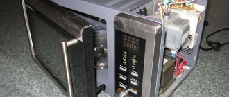
If the documentation could not be found, and this will happen in most cases, do not be discouraged; typical microwave oven malfunctions can be determined without having a circuit diagram. It is enough to know what the main elements look like and where they can be located. A photo of a microwave with the casing removed will help you with this.
Appearance and location of the main elements in the microwave body
The intuitiveness of the process in most cases allows you to remove the casing and get to the main structural elements without an assembly drawing. But in this case, you need to remember the sequence of actions and try not to leave behind “extra” parts after reassembly.
What tools are needed?
In most cases, you can get by with a Phillips screwdriver and a multimeter. In some cases, you may also need a soldering iron. Accordingly, spare parts will also be needed, which ones will become clear after the diagnosis.
Microwave oven breakdowns
Many people are interested in how to check whether the oven produces the required characteristics. In literary sources it is written: the measurement method is in NVN 100 GOST 19308 - 80; Provides a graphic and useful information to guide the assessment process. The beginning of the paragraph is taken from a book on repairing microwave ovens, published in 2003. It is alarming that GOST is difficult to find in practice. The authors googled and found GOST R IEC 60705-2011. And the document is called “Household microwave ovens. Methods for measuring functional characteristics." It is from him that he is invited to dance further. The book is a little outdated. The text cites increasingly less used microwave oven designs: radiation enters the working chamber from above. In an outlandish modern design move, it was supposed to create a uniform field throughout the volume. Today the waves enter from the right, repairs are carried out differently.
Hundreds of pages are already covered with breakdowns of capacitors, burnout of diodes and fuses. It seems that school-age children know what breaks. It is proposed to discuss an obscure aspect - microwave field, power, distribution of the tension vector, features and danger. When carrying out repairs, we often forget that the device is designed to help the family, and not destroy humanity. A Whirlpool could easily destroy the gene pool if proper safety precautions are not taken.
American scientists have long established that 2.4 GHz devices cannot be placed on your lap (look at today's teenagers). The action negatively affects reproductive function. Cell phones and other gadgets operate on a wavelength of 1-2 GHz (approximately).
Typical faults and methods for their elimination
Before we consider in detail the elimination of the malfunctions listed below, we consider it necessary to warn that before diagnosing and repairing, it is necessary to physically disconnect the device from the power supply, that is, pull the plug from the socket.
There is no response to the power button.
In this case, diagnostics and repairs should follow the following algorithm of actions:
- We check the presence of voltage in the power supply network. If it is not there, we solve the problem with the power supply, otherwise we move on to the next step.
- Checking the power supply of the control module. Let's start with the fuse. If it is burnt out, we replace it. After that, turn on the device and try to heat, for example, a glass of water. If everything works, the repair is complete. If the fuse blows, the problem is in the control module and should be repaired or replaced.
In order to independently repair the control module, you must have certain skills in radio electronics; without them, it is not recommended to start repairing the control module yourself.
Example of fuse location on the control module
The microwave oven does not turn off after operating the mode.
In most cases, this problem indicates a faulty door position microswitch. To fix the problem, we find, check and, if necessary, replace the switch.
If the microswitches are normal, then the problem may be related to the relay that supplies voltage to the power transformer in the magnetron power circuit. We “ring” the relay contacts with a multimeter, if they are “stuck”, we replace the electrical switch with a new one.
When no problems are found with the relay, it means that the malfunction is related to the control unit, we replace or repair it.
Low heat.
Most often, this malfunction is associated with a voltage drop in the household electrical network. If it drops below 205.0-210.0 V, a sharp decrease in the intensity of the microwave flux occurs. This problem is typical for private houses in rural areas, where overvoltage of the power grid regularly occurs, and as a result, voltage drop.
If the multimeter shows the permissible voltage level of the household network, then you should check the power circuit of the magnetron, as we will describe how to do this in the next section.
When diagnostics of the magnetron circuit do not produce results, then everything points to problems with the control module.
No heating.
Such a malfunction clearly indicates a malfunction in the magnetron power circuit. Diagnostics is carried out as follows:
- Using a multimeter, we check the presence of voltage on the primary winding T1 (see Fig. 1). If it is not there, the problem should be looked for in the control module.
- The presence of voltage indicates that it is necessary to check the high-voltage circuit fuse, transformer T1, fuse, capacitance C1, diode VD1 and the magnetron itself. Checking the listed elements is carried out with the power off!
- We “ring” the fuse with a multimeter, switching it to the mode of checking diodes or measuring resistance. If the device shows a break, replace the fuse.
- We check T1, open circuit and short circuit of the primary and secondary windings.
- We test capacitance C1; how to test a capacitor using a multimeter was described on our website.
- “Let’s call” VD If anyone is unfamiliar with diode testing technology, you can familiarize yourself with it in a previously published article.
- Checking the magnetron. There are certain features with its testing, so let’s look at this process in more detail:
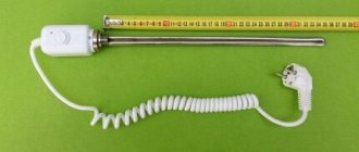
- First of all, it is necessary to “ring” the filament, if the multimeter shows a resistance close to zero (see a in Fig. 6), then everything is fine with it, we continue testing. If the device shows a break, check the contact of the filter coils (marked with yellow arrows in b Fig. 6). If there are problems with the coil mounting contact, the device can be restored, otherwise, everything indicates the need to replace it.
- After testing the thread, we check the feed-through containers for breakdown. To do this, we switch the multimeter to the “continuity” mode, touch the body with one probe, and alternately touch the magnetron contacts with the second (b in Fig. 6). A normal indicator would be infinite resistance, otherwise everything indicates that the capacitance is broken, which means that the magnetron needs to be replaced.
- If the magnetron test does not produce results, it is necessary to measure the input voltages on the device. If they are below the permissible parameters, this may be caused by an interturn short circuit in a high-voltage transformer or a reduced power level in the household electrical network.
Rice. 6. Checking the magnetron
Important! The magnetron must be replaced with a similar one. This is due to the fact that the parameters of the high-voltage transformer and control circuit are calculated based on the specific model of the microwave generator.
Sparking is observed.
This malfunction may be caused by the following reasons:
- Burnout of the mica plate that insulates the waveguide from splashes and pieces of food . The plate is located inside the chamber on the magnetron side. The condition is determined visually. If the problem is related to the plate, it is enough to replace it.
- During operation, the coupler cover burned out . This is a plastic cap that rotates the tray. In this case, only replacement will help. Naturally, it is necessary to install a coupler from models of the same type, since the design of such a cover can be different even from the same manufacturer.
- The “wrong” utensils are installed in the chamber . We remind you that metal utensils, as well as those with metallic dyes, cannot be used in microwave ovens.
The tray does not rotate.
First of all, you need to check that the pan is not blocked by any foreign object, whether it is installed correctly or the separator. If everything is fine, then the reason lies in the drive. This may be due to the following reasons:
- A jammed motor (detected tactilely) or a break in one of the windings (continuity check is carried out). In these cases, the drive needs to be replaced.
- Gearbox problem . In this case, everything depends on the design. In some cases, the gearbox can be repaired. But, as practice shows, it will be easier and cheaper to replace it.
No response to the control panel.
In modern electronic models, such a malfunction indicates problems with the control module. In products with an electromechanical control system, it makes sense to check the mechanical relays and/or switches and, if necessary, replace faulty parts.
When turned on, the scoreboard does not work.
If the power indicator lights up when turned on, but the digital display does not work, then everything indicates problems with the control module. It needs to be repaired or replaced.
The fuse blows when the door is closed.
A characteristic indicator of faulty microswitches on the door position. One of them is “stuck” and does not switch, resulting in a short circuit in the control circuit. Repair consists of replacing or cleaning microswitches.
Microwave field distribution inside a microwave oven
Attention is paid to the distribution of the field inside the working chamber of the microwave oven, that's why! The conditions for the propagation of electromagnetic radiation are variable. If the field structure is constant within the waveguide, in the working chamber it strongly depends on the amount and type of food. Initially, the compartment is manufactured at a resonance frequency of 2.45 GHz; As soon as food gets inside, the parameter floats away, and various parasitic effects appear. Not all are bad (negative), but in the chaos there appear places, sections of the compartment that are poorly heated, or, on the contrary, heated too much. Cheap microwave ovens have rotating tables. A variable panorama ensures the appearance of uniform heating.
In expensive microwave ovens, the tray is motionless; the design of the chamber creates conditions for a constant and uniform field pattern. Readers already have a question mark in their head the size of a house! If the light bulb is on, it’s dark behind the closet, but it’s light under the chandelier. It is not difficult to understand the sequence of light and shadow. Ilyich's light bulb does not emit a fixed frequency - a band! As a result, the interference pattern escapes the eye. Coherent waves can add and subtract better. Same frequency. Let physicists avoid criticizing the review for being too loose in its interpretation of the concept of coherence, an overlooked aspect of the phase of electromagnetic oscillation.
The wave enters the working compartment and begins to be reflected by the walls in an incredible way. As a result, at an arbitrary point in space, two oscillations can meet in phase or antiphase. The picture is exactly the opposite (light, shadow).
In the first case we see double the power, in the second – zero! If the human eye noticed a frequency of 2.45 GHz, the working chamber of a microwave oven would appear to the individual as dotted with spots, stripes of light and shadow. It is important to prevent food from being found in the zero field.
After repair, if work was carried out on the magnetron and waveguide, the picture will be unpredictable. Knowing Russian craftsmen, we are sure that in the country there will be a dozen microwave ovens containing a radar magnetron. Indeed, what a difference it makes on the microwave runway and in the microwave kitchen. In this case, it is recommended to check the parameters using the methods indicated below to assess the security of people operating the device. There is probably no special equipment at home, so it is suggested to simply place glasses of water on this side of the door and wait to see if it heats up. Now the measurement technique is in accordance with GOST R IEC 60705-2011.
An example of a step-by-step repair of an LG MB-4022G microwave oven
There can be many reasons for breakdowns and malfunctions of a microwave oven, as you have already seen above. Most often, this is a failure of the magnetron itself, due to improper operation of the device, namely the use of utensils not intended for cooking in a microwave oven. Also various metal parts that may accidentally end up inside during operation.
Failure of the magnetron can be considered the most unpleasant reason, since replacing this part is not worth proofreading. In this case, it is easier to buy a new stove.
But sometimes there are minor breakdowns that can be easily fixed without special tools and without spending a lot of money.
Below, the article will describe one of these breakdowns and a method for eliminating this malfunction. The photo shows a stove that has stopped turning on and does not respond in any way to manipulation of the control knobs.
Rice. 7. LG MB-4022G
Before removing the protective casing from the oven, you must carefully inspect the power cord and the plug itself for damage, breaks and cuts. If there are any, then the oven should be disassembled.
To do this you will need a Phillips screwdriver.
We turn the oven with the back side facing us, and after unscrewing the two fastening screws, remove the ventilation cover. Next, remove the protective cover.
Rice. 8. Remove the protective cover
Rice. 9. Unscrew the screws
It is secured at the back with several screws. We unscrew them all.
When all the rear screws are unscrewed, move to the side, left side.
Rice. 10. Unscrew the left side
There are three mounting screws, two at the bottom and one in the middle. They should also be unscrewed. As you unscrew the screws, you can see how the metal edges of the cover move away from the chassis of the case.
Rice. 11. We continue to unscrew the screws and remove the covers
Next, lift the lid up a little and pull it towards you. Thus, it comes out of the grooves located on the front of the case.
Rice. 12. Cover from the inside
You can notice traces of soot that were formed due to high temperatures.
The removed cover freed access to the main elements of the microwave oven (Fig. 13). At the top, you can see elements for the grill - a heating element located in a special housing.
Rice. 13. Microwave interior
On the left is the magnetron itself (Fig. 14), namely its upper part.
Rice. 14. Microwave oven magnetron
At the bottom left is the power filter, from which the wire harness and network cable extend. On the top of the chamber, you can see two temperature sensors. They are attached to the body and react to temperature changes. Two wires are connected to them.
Rice. 15. Power filter and 2 temperature sensors
If you look from the side, other elements are revealed to the eye. For example, a power transformer with a step-up winding.
Rice. 16. Power transformer
We also see the magnetron radiator.
Rice. 17. Magnetron radiator
And inspect the power switch.
Rice. 18. Power switch
A time relay with an audible signal, the role of which is played by a mechanical bell (Fig. 19).
Rice. 19. Time relay
Fan for blowing the magnetron radiator (Fig. 20). It prevents this important expensive part from overheating.
Rice. 20. Magnetron blower fan
There is almost nothing on the right side (Fig. 21).
Rice. 21. Right side
Let's start by inspecting the power filter, because it is where the network cable comes, and then the voltage from the board goes to other elements of the oven. Therefore, the place where the voltage “disappears” must be looked for on the side of its supply, that is, the network cable.
So, on the power filter board we find the terminals where the power wires come, namely blue and brown (Fig. 22).
Rice. 22. Power wires
We plug in the power cord and measure the voltage in this section of the circuit. The device shows that the network voltage is 220 volts coming to the board. This means that the power cord is one hundred percent intact, which means that the problem is located further down the circuit.
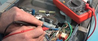
Rice. 23. We measure the voltage on a section of the circuit
There is a fuse on the power filter board, which may be the reason why the voltage does not pass further.
Rice. 24. Check the fuse
Using a circuit tester, we measure the integrity of the fuse. This can be done without removing the fuse from the mounting clips, only before doing this you need to de-energize the device by unplugging the power plug from the socket.
The device shows a circuit, which means that the fuse is intact and the problem is not in it.
Next, pay attention to the brown wire (Fig. 25), through which the voltage passes further and goes to the temperature sensor.
Rice. 25. Brown wire
Here, this device is responsible for disconnecting the microwave oven from the network if the body temperature is critical, that is, more than 150 degrees. At this temperature, the bimetallic contacts located in the device body open and interrupt the circuit. After the body cools down, they return to their original position.
You can check its integrity with the same device that measures the integrity of the circuit (Fig. 26).
Rice. 26. Checking the temperature sensor
To do this, remove one end of the wire from the terminal so that the circuit does not give false readings. We connect the probes of the device with the sensor leads and look at the result. As you can see, the device shows an open circuit, which means that the sensor is not working.
Now we can assume that the cause of the furnace malfunction has been found, but the final result will be known only when the issue with the temperature sensor is resolved.
To restore the sensor's operation, sometimes a sharp shake or hitting it with some object, for example, pliers or the tip of a screwdriver, helps. But even if the device is restored, there is a risk that in the event of critical overheating it will not work, and the consequences could be dire.
Therefore, in order not to take risks, it is better to replace the device with a new one, especially since its cost is about two dollars. You can easily find it in one of the online stores.
The photo shows the thermal switch markings.
Rice. 27. Thermal switch marking
Rice. 28. Temperature sensor: rear view
This thermostat is bimetallic KSD 201.
The markings indicate that it shuts down when the temperature is above 145 degrees and is restored when the temperature drops below 60 degrees.
Removing the sensor is not difficult (Fig. 29); just use a screwdriver to pry up one of the fastening lamellas, and it will be easily removed. Before removing it, you need to disconnect the wires. If you swap the wires when installing a new sensor, this will not affect its operation in any way.
Rice. 29. Remove the sensor
After purchasing this device, we install it in its original place and connect the wire from the filter board to it. We do not connect the second wire yet. The sensor head should fit snugly against the camera body. We connect the device to the terminals of the temperature sensor and check its integrity.
Now the device shows the circuit (Fig. 30), and this means that it is intact. Next, we connect the second wire and check the quality of the connection by tugging on it.
Rice. 30. Check the integrity of the new sensor
Now we plug in the power plug and use a voltage indicator to check whether voltage is reaching the sensor. To do this, connect one probe of the device to the blue wire on the power filter board, and the second to the sensor - the near end - to which the brown wire comes.
Rice. 31. Check whether voltage is reaching the sensor
If the result is positive, and in the photo (Fig. 31) this is exactly the case, then we measure the voltage at the sensor output (Fig. 32). The device shows that it is also present, as in the first case.
Rice. 32. We measure the voltage at the output of the microwave temperature sensor
Now we can assume that the sensor has been successfully replaced.
Although it is undesirable to do this, without putting on the protective casing, we apply voltage to the stove and, having set the minimum temperature, turn on the device.
The oven has started and is working (Fig. 33).
Rice. 33. Checking the functionality of the microwave oven
We quickly turn off the device and put on the protective metal casing.
You need to install the housing cover in the reverse order, that is, by inserting the front part into the grooves and securing the back part with screws.
Rice. 34. Put the lid back on
Rice. 35. Continue assembly
To final check the operation of the device, we turn it on to the network. We put some food in a glass jar inside and start the oven using the time relay handle.
The oven is operating and the food is heating up and producing steam.
Rice. 36. The microwave is working properly
The problem was fixed and it turned out to be not difficult or expensive at all!
Final Recommendations
When repairing a microwave oven yourself, it is important to follow three simple rules.
- Under no circumstances should you remove the magnetron yourself.
- You cannot extend the service life of a burnt-out emitter by turning it over.
- Any microwave repair must be completed with a safety check, just like when using conventional household appliances and tools. Your health depends on it. Pay special attention to its shielding and the degree of microwave irradiation.
In both cases, the operating mode is disrupted and a part of the microwave radiation is released to the outside, which cannot be eliminated with your own hands without special laboratory equipment, and the cost of its use is a reason to think about it.
To consolidate the material, we recommend watching the video by the owner of Oleg pl “Repairing a Samsung microwave oven.”
Ask questions about the topic of the article and video in the comments. Now it’s convenient for you to share this material with your friends on social networks.