I was reading the tape and came across a question about how to increase the reception range of a radio receiver. Miracles do not happen, and winding a bunch of wire instead of an antenna will not solve the problem. Building some kind of wave channel, biquad, in-phase, etc. in the car is not an option. The antenna needs to be broadband and omnidirectional, and such antennas have practically no gain. What could be simpler and wider than a piece of wire? )) So we will use it. Although you can connect a standard car antenna, if available.
So, how can we increase the signal strength at the receiver input? Of course, make an amplifier for the FM (VHF) range. Wandering around the Internet, I found different schemes, but I was only interested in broadband schemes, since the band width is approximately 20 MHz, I not only didn’t want to set up bandpass filters, but also had nothing to do with it. I chose a broadband amplifier codenamed fir cone... brrr))) NK138, distributed as a kit for self-assembly aka KIT, there is also a kit NK147 on one transistor, with a lower gain.
I brought it to life on a small piece of PCB, with minor changes in the circuit.
I soldered the case from tin, soldered the connector for the radio, took power from the wiring from the radio, on which + appeared after turning it on. Pioneer radio with radio and mp3 player. This amplifier lived in my 9, received it regularly
on a piece of wire,
all
radio stations
in the city
, when 20-30 km away from the city, received strong stations, which the receiver stopped picking up when leaving the city at 10 km.
There was a little more noise, but the sensitivity compensated for all the inconvenience. With a normal external antenna on your car, reception will be much better.
Unfortunately, there are no photographs of the finished device, it was made in one copy, the seal was made by LUT. The print size is 42.5x22mm, there is a file in SL5 format. The link above has a description of the amplifier and photos of seals for the dip components.
A little about transistors. You need to use microwave transistors with minimal noise figure; BFR91A is the best option in my opinion. You can use KT3198G or KT368. The price per transistor depends on the greed of the seller... but you can find it from 10 rubles per piece. The cost price will be around 50 rubles.
Every car enthusiast can make an antenna for a car radio with his own hands. This mechanism will help you better catch radio signals. It can be made to fit the body of any vehicle.
How a car antenna works
Such a device is necessary to receive electromagnetic waves. It begins to convert the energy flow of these waves into an electrical signal. After these manipulations, this signal can be amplified and converted. Reception of such waves is possible only when the antenna is tuned to the required frequency or frequency range.
In order for it to capture the required frequency range, you need to choose the right length, because The quality of the received signal and sound will depend on this. In order for the device to pick up FM frequencies, the antenna must be at least 750 mm long. This explains the relationship between the size of the device and the quality of the resulting sound.
To make an antenna for a radio with your own hands, you should first decide on the type of mechanism.
There are several types, each of which is used for its own purposes.
For example, an active antenna is an electronic mechanism that combines a radio wave receiver and a radio frequency amplifier. It is capable of processing a weak signal that is sent to the canvas, then to the body of the amplification device, after which it is transmitted via cable to the antenna input of the car radio installed in the vehicle interior. Passive antennas can only receive signals from local stations.
ANTENNA AMPLIFIER FOR CAR RADIO
All car enthusiasts have radios in their cars, but not all radios pick up the radio well. Only expensive devices are equipped with serious receivers with good UHF, capable of receiving weak FM stations. Most cheap car radios only work acceptably in the city, so it makes sense to equip them with an antenna amplifier. There are two options here - buy a ready-made industrial one or solder it yourself.
Antenna amplifier Ratex
For those who have some amateur radio skills, a couple of circuits of such amplifiers are offered.
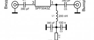
Schematic diagram of an FM amplifier for a car radio
The input coil L1 consists of four turns of enameled copper wire (frameless) on a mandrel more than 5 mm in diameter. Coil L2 is similar to L1, but has only three turns. The pinout of the 2SC2570 is shown in the diagram.
Second option FM UHF
Schematic diagram of an FM car radio amplifier
Together with a good directional antenna, this two-stage antenna amplifier for the VHF FM range will allow you to get clear reception even of distant radio stations. The amplifier will also significantly improve the reception quality of local city FM signals. It is recommended to use imported transistors, as the result is much better with them. Some of them, including the pinout, are shown in the table.
The gain of the second MOSFET is controlled by resistor P1, which sets the bias voltage for T2. For example, if you live near a powerful VHF-FM and TV transmission center, then you understand that high gain will lead to cross-modulation and other unwanted effects in the FM band.
The amplifier is assembled on a double-sided printed circuit board shown in the figure. Coils L1, L2 and L3 are wound on a 4.5 mm frame.
More about coils
FB1, FB2, FB3 = 5 turns of 0.15 mm wire on ferrite beads.
L1 = 7 turns 0.9 mm dia. enameled copper wire; internal diameter 5 mm.
L2, L3 = 7 turns 0.9 mm, winding diameter 5 mm;
L4 = 30 turns of 0.15 mm diameter enameled copper wire on a 1 MΩ resistor with a power of 0.5 W.
In the absence of instruments, tuning can be done by ear - to the maximum quality, using a bad antenna (a small piece of wire).
el-shema.ru
How to do it yourself
Many car enthusiasts are interested in the question of how to make an antenna for a car radio with their own hands. For a homemade antenna, you will need to prepare all the necessary tools and strictly follow the step-by-step instructions.
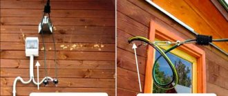
Before installing the antenna in the car with your own hands, you need to prepare the place by clearing it of accumulated dirt and dust.
Required spare parts and tools
The set of necessary tools and spare parts includes:
- anchor bolt;
- soldering kit;
- about 3000 mm of soft wire made of copper;
- plastic case;
- circuit for an amplification device;
- transistor KT368A;
- wire that will lead into the car interior;
- for an active dipole - resistors and capacitors.
Manufacturing process
First you need to wrap the wire around the anchor bolt. All turns should be smooth, there should be no overlaps. Then you need to solder the wire leading to the car radio in the cabin to the winding. You should select a plastic case that matches the resulting design and the size of the standard location for the antenna.
You can proceed to installing the mechanism on the roof of the vehicle. There are several ways how this can be done:
- using magnets;
- using vacuum suction cups;
- clamps;
- install a place for a standard antenna;
- using thread.
The wire should be routed along the body, preferably along one of the vehicle pillars. You can drill 2 holes in the housing; it is advisable to lay the wire around the perimeter of the doorway and secure everything.
After installation, you should lay the cable along the side and connect it to the radio.
Installation of the radio receiving mechanism on the car body using the connector provided:
- Take the wire and cut the thread.
- On one side, the thread must be longer than the height of the insulator, because there will be 3 more nuts.
- Tighten the first nut.
- Insert the wire into the insulator connector and tighten nut No. 2.
- Secure everything with a locknut.
- Insert the insulator into the hole located on the transport body.
- Strip the central core of the radio cable.
- Wind several turns of the protected core and secure everything with nuts.
- Connect the wire shield to the vehicle body.
- Connect the antenna connector to the second end of the cable.
- Secure the cable in the interior. For these purposes, it is recommended to use heat-protective glue.
If the user has chosen an active type of receiving mechanism, then it must be installed on the windshield using the bracket of your choice with a vacuum suction cup.
All installation and connection work must be carried out with the vehicle's power unit turned off.
Amplifiers
Circuit of a broadband antenna amplifier (URF up to 200 MHz)
The amplifier, the circuit of which is shown in the figure, can be an antenna amplifier for an all-wave radio receiver. It can operate at frequencies from tens of kilohertz to 200 megahertz. The gain at 100 MHz is 20 dB. The amplifier is quite linear, so the gain is ...
4 5448 0
Use of MV and UHF television antenna amplifiers, circuits
It was already noted above that installing an antenna amplifier near the TV between the feeder and the antenna input of the television receiver increases the gain of the receiving path, i.e. improves the sensitivity limited by the gain. It has been shown that when using modern...
0 6138 0
Simple high frequency (UHF) amplifiers for receivers
High frequency amplifiers (UHF) are used to increase the sensitivity of radio receiving equipment - radios, televisions, radio transmitters. Placed between the receiving antenna and the input of the radio or television receiver, such UHF circuits increase the signal coming from the antenna...
4 7562 0
Transistor video buffer amplifier
A video buffer amplifier is used wherever using a video player with a TV receiver/monitor using a long cable can cause a drop in signal amplitude and, as a result, deterioration in image quality. The amplifier can also be used to connect multiple receivers...
0 4786 0
Antenna amplifier circuit based on op-amp
The impedance of any sufficiently long wire antenna on the broadcast bands is typically several kilo-ohms, and is difficult to match to the 50-ohm receiver input. In addition, several receivers cannot be connected to one antenna at once, as this will lead to mutual...
0 4764 0
Active antenna from 100 kHz to 30 MHz
This circuit uses direct coupled field-effect and bipolar transistors to achieve good performance even with a short receiving antenna (70 cm). Potentiometer R5 can be used to adjust the gain, and...
0 4219 0
High frequency loop antenna (5-30 MHz)
Good reception quality in the 5-30 MHz range is ensured by an amplifier with a very high input impedance and low noise level. This amplifier can operate into a 75 ohm load at high signal levels at frequencies above 30 MHz. If you connect...
0 4702 0
Active dipole antenna (100 kHz to 40 MHz)
This active antenna operates in the same way as a conventional dipole and consists of a dual FET source follower and a differential amplifier. The LM759 chip generates a virtual ground level equal to exactly half the voltage...
0 4323 0
Wideband reversing amplifier
The amplifier has the same gain in the frequency range of 0.25,..8 MHz and provides uniform gain in the amateur radio ranges (160, 80 and 40 m), expanding the range of uniformly amplified frequencies...
1 4231 0
Antenna amplifier for VHF radio
Water While repairing cheap Asian radios, I encountered the problem of low sensitivity of their receiver in the VHF range. Pairing the settings did not bring any noticeable improvements, so I chose an antenna amplifier. After checking several...
5 5968 0
Connection and setup
The design of a car antenna for receiving radio in a car includes 3 wires:
- For grounding and installation of the receiving device. It is connected to a metal fastener and screwed on.
- Wire for power supply. It must be connected to the wire coming from the radio receiver.
- Contact. It is installed in a special connector, which is on the car radio body. In some devices, the power and contact wires can be combined into one common one.
How to determine if the signal is weak
You should install a car antenna amplifier only if the signal level is low. The main features can be called:
- Frequent interference.
- Sound distortion when listening to a radio station.
- Lost image synchronization.
- Periodic complete disappearance of the signal.
For a radio, an amplifier is a device that can increase the signal level. In this case, the transmission quality can be doubled. You can install the device yourself, there are no problems with this.
Reasons for a bad signal
The amplifier for the car antenna is selected taking into account the reason that led to the problem. The main ones can be called:
- Malfunction of the antenna and other elements. High humidity often causes oxide to form, which impairs contact.
- Hissing and wheezing while listening to the radio indicates a malfunction of the receiver itself. In most cases, the problem is a cracked circuit board.
- Additional interference degrades the signal quality in the car. They can be created by mobile operator towers, power plants, and railway tracks.
- Moving away from the signal source also causes a decrease in the quality of reception.
- Additional interference may be created when the recorder is connected to a power source via the cigarette lighter. This problem can be solved by installing equipment that runs on a built-in battery.
Are you a car driver?! Then you can take this simple test and find out. Go to test »
In most cases, artificial interference and distance from the source cause signal deterioration. It is recommended to amplify the radio in case of frequent long trips.
Antenna amplifier for car radio: how to choose
Antenna amplifier for car radio
The antenna amplifier for the car radio is designed for better and more reliable reception. Recently, inexpensive car radios have begun to be produced, although with good functionality. Unfortunately, they are not able to provide reliable reception of radio stations. This is especially true for areas far from the city, where there is a signal level, but it is too weak. For a car radio, the antenna amplifier in this case acts as a device that sharply increases reception. If earlier cassette tape recorders were found quite often, today they can only be seen in vintage cars. Modern car radios are more multimedia complexes equipped with a huge range of options. Yes, modern equipment does an excellent job of navigation, plays excellent music from various media, helps the driver park, etc. But a motorist will always miss a radio or TV on the road - an experienced motorist knows this!
Antenna amplifier for car radio
As mentioned above, a modern multimedia center is not capable of providing a good radio signal, especially outside the city. Then you have to purchase an antenna amplifier - a special device that significantly increases the power and quality of the signal.
How to determine if the signal is weak
Antenna amplifier for car radio
This is not difficult to do. It will be enough to familiarize yourself with the signs of a weak radio or TV signal, which are given below:
- The sound is distorted when watching or listening. Frequent interference;
- The list of accepted stations is sharply reduced;
- Image synchronization is lost;
- The signal disappears completely;
- Small white dots are visible on the screen instead of a picture, only noise is heard.
Getting to know the device
Antenna amplifiers for car radios and their installation
This amplifier is specially designed for efficient and reliable reception of stations. Most motorists who have installed an antenna amplifier in their car note that the signal has doubled, if not more.
Note. The device does not require any special skills to install. Its connection is simply connecting one contact to the head unit, and the other to the external passive dipole.
Antenna amplifiers for car radios
Almost all modern antenna amplifiers for cars are assembled using a two-stage design, although they may have some differences. But they must meet the standards of modern communication systems.
Selection options
Antenna amplifier for car radio circuit
When choosing an antenna amplifier, it is recommended to follow the tips below:
- Primary attention should be paid to the possibility of installing the amplifier not far from the antenna.
Note. You should know that connecting directly next to the car radio input, on the one hand, significantly increases the signal level, and on the other hand, it threatens interference emitted by electrical equipment.
- We remember that the operating band must cover the required frequency range;
- The amplitude-frequency response should be as uniform as possible;
- As for the gain, it is desirable that it be in the range of 15-25 dB;
- When the supply voltage varies, stable operation must be ensured;
- The dynamic range must also be high, which helps protect against overloads;
- Finally, the noise figure must be much less than the signal-to-noise value.
Note. The gain is worth paying the most attention to. The fact is that with its small values, the reception quality cannot be high. On the other hand, for the city these same indicators are quite normal. If this same coefficient is too high, the broadband amplifier may be overloaded, which can lead to its damage.
Inevitable factors that affect the signal
Note. Note that the best effect is achieved if you connect the amplifier to an external antenna. Thus, an active rather than a passive dipole is connected. Distance is also important. So, you should not count on high-quality reception if the station (main transmitter) is located at a distance of more than 120 km.
It is worth noting that there are side factors that in one way or another affect the signal level:
- In the city itself, signal over-amplification may occur. The manufacturer recommends either turning off the amplifier in a city area or reducing the gain;
- It is also not recommended to use the amplifier simultaneously with an active antenna. This can lead to the opposite effect: the signal will deteriorate and distortion will appear;
- After replacing the head unit, interruptions in signal reception may be noticed. It turns out that the problem may lie in the power supply, which was forgotten or could not be connected to the active antenna. Buying a special adapter or making one will immediately solve the problem.
What to choose
Today, the manufacturer offers not just one, but a whole host of amplifier options for a car antenna.
Domestic manufacturer
Amplifier Triad
It is interesting that our domestic manufacturer also offers a whole line of products called Triad. All models deserve praise, and especially the amplifier for the car radio antenna Triada-304 Dalnoboi, which is equipped with the function of turning off the device and operating in the FM/AM/VHF radio bands.
Foreign manufacturer
Amplifier from Prologi
Among foreign manufacturers, Prologi products take pride of place. For example, their model TFB-100 is capable of amplifying digital and analogue signals and simultaneously working with two antennas.
On your own
Yes, there is such an option. For radio amateurs, it offers special kits from which you can assemble a full-fledged amplifier with your own hands . Again, homemade amplifiers are assembled using a two-stage circuit. Well, now you have learned how to strengthen the radio signal in your car radio. Installing an amplifier purchased or made by yourself will not take much time and effort. All you have to do is follow the instructions, watch the video review and study useful photo materials. The price of amplifiers varies and it all depends on the reception range, as well as the manufacturer.
avtozvuk-info.ru
Amplifier selection criteria
You can choose a suitable antenna amplifier for your car radio by taking into account various recommendations. They are as follows:
- To begin with, pay attention to the fact that the device must be located in close proximity to the antenna.
- The operating band must cover the required frequency range. Due to this, you will be able to listen to all available radio stations.
- The amplitude-frequency response should be as uniform as possible.
- The gain is selected in the range of 15-25 dB.
- Stability of operation must be ensured when the supply voltage varies.
- The dynamic range is selected taking into account the need to protect the device from overload.
- The noise figure is much less than the signal-to-noise ratio.
- It is recommended to give preference to devices from popular brands. They last much longer and have more attractive properties.
The FM frequency, when installed with a suitable amplifier, will be virtually interference-free. However, in some cases there is a possibility that such an element will cause noise at a high signal level.
Features and circuit of the antenna amplifier
An amplifier is a device designed to amplify a poor, unstable TV antenna signal. The advantages of this device are as follows:
- amplification of a television signal in a fairly wide frequency band;
- the ability to receive even a very weak TV signal;
- quiet operation.
The disadvantages include:
- the risk that the device will self-excite;
- High power signals in the meter wave range may overload the device;
- susceptibility to the effects of lightning currents;
- passive output losses.
The DIY antenna amplifier diagrams indicate how the device should be connected to the TV. The TV cable goes to a device that amplifies the signal, and then the signal goes to the TV. This scheme is universal.
Best models
There are practically no popular models among amplifiers. Such devices are installed extremely rarely, since a modern multimedia system allows you to play music from various media. When determining a popular model, the following points are taken into account:
- Device cost. A proposal of domestic origin costs 1000 rubles. Do not forget that the price determines the basic properties of the device.
- Length of service life. Installing an amplifier involves changing the receiver connection circuit. Therefore, you should connect a device that can last for several years.
- Reliability. The device must operate under various operating conditions: voltage changes, temperatures, humidity and other situations.
- Signal level. This indicator can vary over a wide range.
General article for beginners of AutoRadio Communications - ABOUT THE AMPLIFIER
- General article for beginners of AutoRadio Communications
- ABOUT WALKIETY
- ABOUT THE ANTENNA
- ABOUT THE AMPLIFIER
- WHAT YOU NEED TO REMEMBER
About the amplifier.
Its main task is to increase the signal power supplied to the antenna. Let us note that this device is prohibited for use, but everyone buys it, disguises it and uses it with might and main if necessary. As a rule, there are no amplifiers on sale, but often there are antenna-matching devices that (lo and behold!) perform exactly the functions we need.
Yes, don’t even think about buying a matcher, this is just an antenna-matching device, but a matcher is not needed when using a walkie-talkie in a car. The main differences between the amplifier are the power parameter measured in Watts, there are wires and a power switch, and there is a massive housing with fins. The matcher costs several times less, but there is no power supplied to it, it is made in a frail tin case, and, by the way, is needed only by those maniacs who work with a walkie-talkie from an apartment; they keep a huge home-made antenna on the roof of the house and therefore cannot run there - here to adjust the SWR whenever weather conditions change. In principle, the matcher can be used in a car, but in the vast majority of cases it is not needed there.
Yes, we're talking about amplifiers. This thing is really useful if you plan to communicate at a distance of 15 or more kilometers from each other. You still won’t be able to communicate more than 35-40 km (the Earth is round), but sometimes it’s simply impossible to communicate without an amplifier. By the way, in Moscow you will practically not talk to the Rescue Service without this device, but, I repeat, officially it can only be used to save people’s lives (in this case the limitation on signal strength is lifted).
And one more thing: if you are talking at very short distances (50-100 meters or even less), it is better to turn off the amplifier. It will significantly interfere.
One more thing: holding the pin with your hand while operating the amplifier is a very bad idea. It's good. And turn off the amplifier in advance if you are stopped at a traffic police post to check your documents. You may well run into a technically competent employee, so you will save both time and money.
Yes, finally: an amplifier of less than 50W is a waste of money. 70-120 W is very good, 200 is just great. The difference in prices is not significant enough to choose cheaper models.
The amplifier is powered directly from the battery. Power wires - stranded copper 1.5-2 sq. mm. Maybe thicker. Installed either under the passenger shelf or under the plastic trim. In the latter case, the power switch is displayed on the dashboard.
<< First < Previous 4 Next > Last >> (Page 4 of 5)
How to make it yourself
You can make a radio amplifier for your car radio yourself. Among the features of the work, we note the following points:
- The circuit is represented by a combination of several resistors. They are connected by soldering. When connecting, you need to carefully clean the contact, as otherwise additional resistance may appear.
- Resistors R1, R2, R4, R6 are used to stabilize the changes occurring in transistors VT1. Changes may include voltage and temperature.
- All elements are selected to ensure maximum amplifier amplitude and frequency performance.
- The circuit includes 2SC29 bipolar transistors, the frequency of which must be at least 1 GHz. This element allows you to reduce the noise that is generated by the device itself during operation.
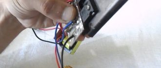
- The device is assembled by soldering all the elements on a special board. You can carry out soldering yourself, which requires a small set of tools. You can purchase the required board at a specialized store.
You can simplify the task of assembling your own amplifier by using special kits.
How to install and connect
After assembling the product, it should be connected. Recommendations for carrying out such work are as follows:
- The external antenna is connected to the amplifier input. For this, a cable with a resistance of at least 75 Ohms is used.
- It is recommended to insulate the cable. Do not forget that high humidity causes the appearance of oxide. At the same time, it is secured with clamps, since strong vibration may occur when moving.
- When connecting, polarity must be strictly observed.
- The power supply requires 12V voltage, which is often used in the car. The board is connected to the ANT radio output. Due to this, voltage will be supplied when the device is turned on.
- When installing the device outside the vehicle, ensure high-quality sealing of the housing. Moisture getting inside the device will cause corrosion.
The advantage of a homemade device is that it can be disassembled and changed at almost any time. By selecting a suitable circuit, the amount of interference is reduced.
A simple built-in low-frequency amplifier on a chip with an FM receiver based on Arduino
A lot of interesting devices and systems are created based on Arduino. But not many of them are used in real life. In most cases, these are toys or just projects just for fun. Even more rare are projects that relate to high-quality sound reproduction. At the same time, Arduino can be used to implement quite decent audio projects for everyday use. That's what we did, creating a high-quality stereo amplifier with a built-in FM receiver and control system. Actually, you can do without an FM receiver and connect other sound sources. But we found this combination convenient. Plus, I wanted to make the project self-sufficient - turn it on, start playing, have fun. We're already getting it. According to the plan, the amplifier should provide very high sound quality with low power. In principle, for a home (and the system was designed specifically as a home system), 2 20 watts will be enough. And the neighbors will treat you well, and the sound will be very decent.
What did we use?
- Digital amplifier D-class, 2 x 20W SANYO.
- Hi-Fi audio processor (TDA8425)
- FM radio.
- Real Time Clock (RTC).
- 2 valcoders with handles.
- Actuator element (BM146).
- Module for connecting a character display (IIC LCD).
- Freduino UNO, 3.3V/5V, ATMEGA328, 16 MHz.
- IFC remote control with receiver.
In principle, any Arduino controller can be used. We took the display WEH002002ALPP5N00001 - it turns out very nice. If you are indifferent to beauty, try LCD for Arduino. You also need a power supply. We used PS-65-15 - a 65 W power supply. 15V. There will be plenty to spare for our purposes. Actually, you can use any one with a voltage of 9-15 Volts and a power of 40 Watts or more. Well, and a red LED - either one will do.
Software and sketch
(download links) Sketch Libraries Library for IIC LCD Ardiuno1.0 Library for IIC LCD latest
How to connect elements to Arduino?
The diagram is quite simple, so we’ll make do with the text.
OLED display with installed IIC LCD module:
C —> 2 D —> 3 L —> 4
Valkoder (from MP1093 set) left:
A —> A0 B —> A1 S —> 9 + power
Valcoder (from MP1093 set) right:
A —> A2 B —> A3 S —> 10 + power
Light-emitting diode:
—> 6
MP1094:
signal -> 7 (first contact square pad) on MP1094 signal location: 1 signal 2 GND 3 VDD
Relay:
—> 8
MP1095:
SDA -> A4 SCL -> A5 + power
MP1090S:
SDA -> A4 SCL -> A5 IN_SEN -> VDD IN_RST -> 13 These signals are output to the 10-pin connector of the MP1090S. Location of signals on the connector:
- 1 (marked with a square pad) - SDA
- 2 SCL
- 3 IN_SEN
- 4 IN_RST
MP1243:
SDA —> A4 SCL —> A5 input 1 —> AUX input 2 —> FM
The MP1090S and MP1243 modules need to be powered from the Arduino.
Control
The amplifier functions are activated by two valcoders, with buttons on the axis.
The right encoder controls both volume and AUX/FM audio source selection. The left encoder controls the timbre (low-high), balance, station frequency selection, and the clock (what could we do without them?).
Here's how it looks and works:
We prefer to make cases from PVC, and now we are making an excellent case for an amplifier.
The device turned out to be of really high quality, and the power is enough to enjoy the sound in a room whose area does not exceed 40 square meters. Do you have more? Next time we will publish an article about creating a more powerful amplifier.
If someone wants such an amplifier at home, then the above elements can be found here or in any other place where peripherals for Arduino are sold.
If you implement this project, we will welcome ideas and suggestions for improving it.