Description and decoding of the device
The PML magnetic starter is a device that combines various switching mechanisms that are needed to start, reverse and stop certain stationary motors and relays. Includes an armature and a core placed on a plastic casing. At the top of the direct starter there is a traverse along the guides, and on it there is a magnetic armature with additional contact bridges and springs.
Detailed description from the reference book
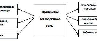
Note! It is worth pointing out that the scope of application of such equipment is extensive. If equipped with current limiters, the starter can be suitable for a microprocessor control system.
The device, which stands for electromagnetic starter, works simply. When current is applied, the armature is attracted to the coil. In this case, open contacts are connected, and closed contacts are opened. The magnetic starter is turned off by opening the normally open contacts and closing the closed ones. Before this, return springs move the movable starting parts backward.
Equipment decoding
Application area
Well, the last of the main questions of the article is what a magnetic starter is needed for (the photo below shows its appearance). As we said earlier, the purpose of this device is to close and open a circuit, which is characterized by high currents. As a rule, starters are used for remote control of electric motors operating at a voltage of 220 or 380 Volts. At home, these devices can be used to create a street lighting system or turn on powerful electricity consumers.
So we looked at the design of a magnetic starter, its principle of operation and purpose. We hope that the information was interesting and useful for you. If you suddenly have any questions, ask them in the comments or in the special category - “Question to an electrician”!
Also read:
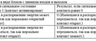
The name of this electrical device for 0.4 kV electrical installations contains two fundamental actions:
1. actuation as an electromagnet from the passage of electric current through the coil winding;
2. starting the electric motor using power contacts.
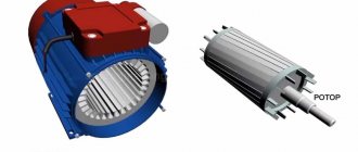
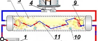
Structurally, any magnetic starter consists of a permanently fixed part and a movable armature moving along skids. It is highlighted in blue in the picture.
How does the electromagnetic system work?
In a very simplified way, the starter can be represented as one button, on the body of which there are terminals with connected power circuits and stationary contacts. A contact bridge is mounted on the moving part. Its purpose:
1. ensuring a double break in the power circuit to turn off the power to the electric motor;
2. reliable electrical connection of incoming and outgoing wires when the circuit is put into operation.
When you manually press on the anchor, you can clearly feel the compression force of the built-in springs, which must be overcome by magnetic forces. When the armature is released, these springs throw the contacts to the off position.
Read also: How to disassemble an Atlanta iron video
This method of manual control of the starter is not used during operation of the circuit; it is used during checks. During operation, the starters are controlled only remotely due to the action of electromagnetic fields.
For this purpose, a coil winding with turns wound on it is placed inside the housing. It is connected to a voltage source. When current is passed through the turns around the coil, a magnetic flux is created. To improve its passage, a laminated steel magnetic circuit was created, cut into two parts:
the lower half permanently fixed in the device body;
movable, part of the anchor.
In the de-energized state, there is no magnetic field winding around the coil; the armature is thrown upward by the energy of the springs from the stationary part. Under the influence of magnetic forces arising after the passage of electric current through the winding, the armature moves downward.
Attracted to the stationary part of the magnetic circuit, its movable half creates a single structure with minimal magnetic resistance. Its value during operation is influenced by:
violations of adjustment adjustments;
corrosion of steel parts of the magnetic circuit and its fastening;
technical condition of springs, their fatigue;
defects in the short-circuited turn of the magnetic circuit.
The movement of the anchor inside the housing is limited by two boundary values. In the lower pulled position, a reliable clamp of the contact system must be created. Its weakening leads to burning of the contacts, an increase in the value of the transient electrical resistance, excessive heating and subsequent burning of the wires.
An increase in the magnetic resistance of the magnetic circuit for any reason is manifested by an increase in noise due to the appearance of vibrations, which lead to a weakening of the clamping of the contact system and, ultimately, to failures in the operation of the magnetic starter.
How does the power contact system work?
Structurally, power contacts are designed for reliable and long-term operation. For this they:
made of technical silver alloys applied by special methods to copper jumpers;
created with a margin of safety;
manufactured in a form that provides maximum electrical contact when switched on and can withstand the electric arc that occurs when the load breaks.
Three-phase circuits use magnetic starters with three power and several additional contacts that repeat the position of the armature and are used in motor control circuits. All of them are drawn on the diagrams in a position corresponding to the absence of current in the coil and the uncompressed state of the springs.
When the starter is triggered, the control contacts close (called “closing”) or, conversely, open the circuit. In a pulled position, they create a platform in the form of a point. To do this, the stationary part is made as a plane or a sphere (in critical units), and the movable part as a sphere.
Power contacts are more responsible and must withstand increased loads. They are made to create a contact line consisting of many points. For this purpose, the stationary part is made of a plane or a cylinder, and the movable part is made only of a cylinder.
Magnetic starters produced by domestic manufacturers are classified according to their ability to work with loads of different powers into 7 groups and are designated by increasing values from zero with a switching current up to 6.3 amperes inclusive and up to the sixth - (160 A).
Starters produced by foreign manufacturers are classified according to other criteria.
Electricians servicing magnetic starters and supervising their operation are required to monitor the quality of contact pads and their cleanliness. The existing opinion that “in modern starters the contacts are made reliably and do not need to be inspected” is not entirely correct.
The cleanliness of contacts depends on many factors, including:
environmental conditions.
They all appear differently on each specific device. Therefore, they must be periodically monitored and, at the first sign of contamination, washed with alcohol. When it is not available for such work, they use an ordinary school eraser, which, while cleaning the metal, leaves its crumbs, which have dielectric properties, on the outer surface.
They are removed by wiping the surfaces with thin dried wooden sticks from non-resinous tree varieties. Best suited for these purposes:
When wiping contacts, hardwoods additionally polish the surfaces being treated.
Minor burnout of contact surfaces can be removed with homemade “blues”. This is what electricians call flat pieces of strong metal plates (usually made from broken hacksaw blades for metal), the surface of which is lightly treated with the finest sandpaper.
Read also: Compressor unit lubrication system
Such a tool allows you to remove a very thin layer of burnt metal and bring the contacts into working condition, maintaining their original shape. You cannot use fine sandpaper or needle files for such purposes. You can quickly break the formed contact line. “Sandpaper” also clogs the surface being treated with abrasive crumbs.
Schemes for connecting electric motors with magnetic starters
Easiest controls
This motor connection can be made using the picture below.
Three-phase power ≈380 is supplied through power contacts K1-c to the electric motor, the temperature of the windings of which is controlled by a thermal relay kt. The control system is powered from any phase and zero. It is quite acceptable to replace the working zero with a ground loop.
In order to increase electrical safety, a separation or step-down transformer TP1 is used. Its secondary winding cannot be grounded.
The simplest fuse FU protects the control circuit from possible short circuits. When the operator presses the “Start” button, a circuit is created in the control circuit for current to flow through the winding of the starter K1, which simultaneously closes its power contacts K1-c. The amount of time the worker presses the button is how long the engine runs. For human convenience, such buttons are mounted with a trigger mechanism.
A running electric motor can be turned off when the button is pressed:
removing power from the power distribution board;
by pressing the “Stop” button;
operation of the thermal relay kt when the engine overheats;
Such schemes are used where, according to technology, it is necessary to keep your hands constantly on the equipment and not be distracted from the production process. An example would be working with the press.
Scheme with holding the button by the starter contact
Adding to the considered circuit just one closing contact of the K1-y starter allows you to set the “Start” button to be blocked by this addition and eliminates the need to constantly press it. Otherwise, the scheme completely repeats the previous algorithm.
Reverse circuit
Many machine tool drives require changing the direction of rotation of the motor rotor during operation. This is done by changing the alternating phases of the power circuit - switching the connection points of any two windings with the engine turned off. In the picture below, the windings of phases “B” and “C” are swapped. Phase "A" does not change.
The circuit already includes two magnetic starters No. 1 and No. 2. The motor can only rotate from one of them, clockwise or in the opposite direction. To do this, a break contact for controlling the counter-rotation starter is introduced into the control chain of each winding K1 and K2. It blocks the simultaneous connection of both starters.
To change the direction of rotation of the engine, the operator must:
press the “Stop” button. The gap it creates opens the control circuit and interrupts the flow of current through the operating starter. In this case, the springs release the armature, and the power contacts turn off the power supply from the electric motor;
wait for the rotor to stop rotating and press the “Start” button of the next starter. The current will flow through its coil, the button will be held by the closing contact, and the winding circuit of the reverse rotation starter will be broken by the breaking contact.
Design features of various models
If previously magnetic starters were equipped with power contacts and one or two of their position repeaters for closing or opening, then modern models are equipped with additional structural elements, due to which they have a greater number of capabilities.
For example, complete products from leading manufacturers allow you to perform various functions for controlling three-phase electric motors, including reversing by integrating additional equipment into the starter. The consumer only has to connect the electric motor and power wires to the purchased module, and the circuit itself is already installed and configured for certain loads.
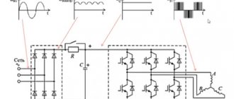
A promising technical solution is considered to be a scheme that allows:
spin the motor rotor to the rated speed by connecting its windings in a star configuration;
switch on under load when switching to delta.
Read also: DIY reversible plow for a walk-behind tractor, drawings
The housings of magnetic starters can be open or protected from the penetration of dust and/or moisture by a special shell with seals.
Some modern models of small power are mounted on a DIN rail.
Powerful magnetic starters can have an arc extinguishing system installed, which occurs when the current is switched off by power contacts.
Electromagnetic starter
(
magnetic starter
) - a low-voltage electromagnetic (electromechanical) combined distribution and control device designed to start an electric motor, ensure its continuous operation, turn off the power, protect the electric motor and connected circuits, and sometimes to reverse the direction of its rotation.
The starter is usually a modified contactor; it can be equipped with additional devices, such as: 1.
Thermal relay for emergency engine shutdown;
2.
Additional low-current contact group or groups used in control circuits;
3.
Or the start button. Sometimes starters are equipped with an emergency shutdown device in case of failure (break) of one of the phases of the three-phase power supply network of three-phase electric motors.
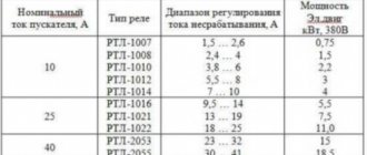
Technical specifications
The electromagnetic starter has a rated voltage of 660 volts, a rated current of 10-40 amperes, a power of 5.5-30 kilowatts, a rated voltage frequency of 50-60 hertz and a switching endurance of 0.3-3 million cycles. It also has a high degree of protection and high-quality additional contacts. It has a plastic case, mechanical and remote control.
Equipment technical parameters
terms of Use
The electromagnetic starter is designed to operate at a temperature of +/-40 degrees Celsius, with a degree of environmental pollution of 3 points and at an altitude of no more than 2 thousand meters. Its normal operating position is to be mounted on a vertical plane using the terminals of the switching coil up and down with screws or by snapping a standard rail. Deviation from the top in any direction is acceptable.
Mandatory use with voltage limiter
The device may only be used in accordance with the instructions. Only in this case is it possible to achieve a positive effect from interacting with it and at the same time maintain its performance while protecting the controlled electric motor from overload and electric current that appears at the moment of a break in one phase.
You might be interested in what a capacitor looks like in the diagram
Use according to instructions
Installation of starters
Contactors and magnetic starters
There are two ways to secure the device in a panel or mounting box:
- on DIN rail;
- bolts.
Mounting equipment on a DIN rail
To fasten electromagnetic starters, automatic machines and other equipment, a metal, sometimes plastic strip with curved edges 35 mm wide is used. Devices designed for DIN rail mounting have a groove and a movable element on the bottom side. During installation, this element is moved aside, the part is put on the rail and fixed by returning the moving part to its original position.
Advantages of this method of fastening:
- Easy to install. During installation, there is no need to drill holes for each device separately - just fasten one metal strip. In factory-made plastic boxes, the DIN rail is integral with the housing;
- Quick replacement of failed elements. Dismantling of faulty parts and installation of new parts is carried out without unscrewing the bolts.
DIN rail starter
Bolting
There are holes at the bottom of the contactors for fastening with bolts. Their number and diameter depend on the modification of a particular device. To install bolts in the panel, you need to mark and drill holes in which the threads are cut.
The advantage of such fastening is higher strength, however, under normal conditions it is redundant.
Marking
The equipment marking or designation consists of 21 characters. They are designated in order:
- group,
- series,
- the size of the contactor by rated current,
- fulfillment as intended,
- performance according to the protective degree,
- design according to the contact number of the auxiliary electrical circuit,
- conditional number of rated connection current,
- the amount of voltage of the coil connected to the network,
- Climatic performance,
- wear resistance design,
- trademark.
Equipment marking
In general, a PML starter is a device consisting of a core and an armature. It is needed to remotely control three-phase motors. Supplied with surge suppressors. It has technical parameters indicated on the device body itself, in the form of markings.
Functionality
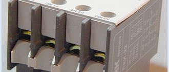
PML contactors are presented in the form of powerful cases, which are cast from durable plastic; the product itself is divided by the manufacturer into a base and a head part. The rod core also consists of two compartments. Each of them is located in a separate part. The head compartment contains durable contacts that most closely resemble the bridges of a moving system. They are necessarily spring-loaded and rigidly attached to the core using a traverse. Of course, the final dimensions of PML switches are relatively small, which is why they belong to the category of small-sized units.
In the head part there are guides along which the moving system moves freely. All those terminals that serve to fix the output and input circuits are installed in the same compartment. The coiled return spring provides a normal open state for the contactor. It is mounted between the body parts. Only thanks to the efforts of this spring, the moving system is fixed in the upper position with open contacts.
Timely magnetization of the W-shaped core occurs due to the influence of a control voltage of the required magnitude, which is supplied to the responsible terminals of the main coil. During such a reaction, approach and closure occurs between different parts of the magnetic circuit. As a result, the power contacts close, and their free counterparts change their voltage.
Since an alternating control voltage with an industrial frequency of 50 Hz can cause a specific rattling effect in the moving section, the manufacturer has provided closed rings. They are mounted on both sides of the central core of the magnetic circuit; reliable fixation is due to factory pressing into special grooves. All currents that act on these rings are able to slow down the change in magnetic flux in the core, minimizing rattling rates.