When repairing radio and electrical products, repairing wiring, there is a need to search for contact of current conductors in a place where a short circuit may occur (in this case, resistance = 0), to search for a place of poor contact between conductors (resistance tends to infinity). In this case, you should use a device called an Ohmmeter. Resistance is designated by the letter R and measured in Ohms.
An ohmmeter is a device (battery) with a digital or dial indicator connected in series. Also, an ohmmeter is used to check measuring instruments and measure insulation resistance at elevated voltages. All multimeters and testers have a resistance measurement function.
Note! Measure the resistance with the devices completely de-energized so that the ohmmeter does not fail. To do this, remove the plug from the socket or the battery. If the circuit includes capacitors with a large capacity, they should be discharged. Short-circuit the leads of the capacitors through a resistor whose rated current is 100 kOhm for a couple of seconds.
In order to use the Ohm measurement, set the slider on the device to the position that corresponds to the minimum resistance value measurement.
Before taking measurements, check the device for functionality. To do this, connect the ends of the probes to each other.
If this is a tester, you need to set the arrow to o. If that doesn't work, replace the batteries. When checking an incandescent lamp, you can use a device whose batteries are discharged and the needle does not set to zero, but when connecting the probes it deviates from “0”.
If there is a deviation from zero, it means the circuit is intact. Digital instruments have the ability to display readings in tenths of Ohms. If the circuit is open, digital instruments flash overload, and on pointer instruments the arrow tends to “0”.
If the device has a function for testing circuits (diode symbol), it is better to test low-impedance circuits and wires in this way. If the result is positive, a beep will be heard.
Checking incandescent light bulbs
The lamp in the lamp does not light? What is the reason? The failure may be in the socket, switch or electrical wiring. An incandescent, energy-saving, fluorescent lamp is checked by a tester. And this is quite easy to do. To do this, set the slider on the tester to the minimum resistance measurement position and touch the base with the ends of the probes.
The screen shows that the filament resistance is 51 ohms. This means that the lamp is working properly. If the thread were broken, infinite resistance would appear on the screen. A 12V, 100W car lamp shows a resistance of 1.44 ohms. A 220 V and 50 W halogen produces 968 Ohms.
The filament will show less resistance when cooled, when the paw is heated, this figure can increase several times. Therefore, lamps often burn out when turned on. This is because when turned on, the current flowing through the thread exceeds the permissible value several times.
Examples from practice of measuring resistance of products
In theory, everything is usually clear, but in practice questions often arise that can best be answered by examples of checking the most common products with an ohmmeter.
Checking incandescent lamps
The incandescent light bulb in a lamp or car on-board devices has stopped shining, how can I find out the reason? The switch, electrical socket or wiring may be faulty. Using the tester, any incandescent lamp from a home lamp or car headlight, filament of fluorescent lamps and energy-saving lamps can be easily checked. To check, just set the device switch to the minimum resistance measurement position and touch the ends of the probes to the terminals of the light bulb base.
The resistance of the light bulb filament was 51 Ohms, which indicates its serviceability. If the thread were broken, the device would show infinite resistance. The resistance of a 220 V halogen light bulb with a power of 50 watts when illuminated is about 968 Ohms, and a 12 volt car light bulb with a power of 100 watts is about 1.44 Ohms.
It is worth noting that the resistance of an incandescent lamp filament in a cold state (when the light bulb is not lit) is several times less than in a warm state. This is due to the physical property of tungsten. Its resistance increases nonlinearly with heating. Therefore, incandescent lamps usually burn out the moment they are turned on.
Unfortunately, LED and energy-saving lamps cannot be checked with a multimeter without disassembling them, since the supply voltage from the base terminals is supplied to the driver diode bridge.
Using an online calculator, you can independently calculate the resistance of any incandescent light bulb or heating element, for example, a heating element, or an electric soldering iron.
| Online calculator for calculating the resistance value based on power consumption | |
| Supply voltage, V: | |
| Power, W: | |
Checking sound-reproducing headphones
It happens with headphones in one of the emitters, or in both at once, the sound is distorted, periodically disappears or is absent. There are two possible options: either the headphones or the device from which the signal is received are faulty. Using an ohmmeter, it is easy to find the cause of their breakdown and repair the headphones.
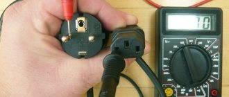
To check the headphones, you need to connect the ends of the probes to their connector. Typically, headphones are connected to the equipment using a 3.5 mm jack connector, shown in the photo.
One end of the probe touches the common terminal, and the other, in turn, touches the terminals of the right and left channels. The resistance should be the same and be about 40 ohms. Usually, the resistance is indicated in the passport for headphones.
If the resistance of the channels is very different, then there may be a short circuit or a broken wire in the wires. It is easy to verify this; just connect the ends of the probes to the terminals of the right and left channels. The resistance should be twice that of one earphone, that is, already 80 Ohms. In practice, the total resistance of series-connected emitters is measured.
If the resistance changes when the conductors move during measurements, it means that the wire is frayed in some place. Usually the wires fray where they exit the Jack or emitters.
To localize the location of the wire break, during measurements it is necessary to bend the wire locally, fixing the rest of it. Based on the instability of the ohmmeter readings, you will determine the location of the defect. If it’s a Jack, then you need to purchase a detachable connector, bite off the old one with a section of bad wire and solder the wire to the contacts of the new Jack.
If the break is located at the entrance to the headphones, then you need to disassemble them, remove the defective part of the wire, strip the ends and solder them to the same contacts to which the wires were soldered before. In the website article “How to solder with a soldering iron” you can learn about the art of soldering.
Measuring the resistor value (resistance)
Resistors (resistance) are widely used in electrical circuits. Therefore, when repairing electronic devices, it becomes necessary to check the serviceability of the resistor or determine its value.
On electrical diagrams, a resistor is designated as a rectangle, inside which its power is sometimes written in Roman numerals. I – one watt, II – two watts, IV – four watts, V – five watts.
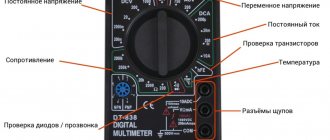
You can check the resistor (resistance) and determine its value using a multimeter turned on in resistance measurement mode. In the resistance measurement mode sector, there are several switch positions. This is done in order to increase the accuracy of the measurement results.
For example, position 200 allows you to measure resistances up to 200 Ohms. 2k – up to 2000 Ohm (up to 2 kOhm). 2M – up to 2,000,000 Ohm. (up to 2 MOhm). The letter k after the numbers denotes the prefix kilo - the need to multiply the number by 1000, M stands for Mega, and the number needs to be multiplied by 1,000,000.
If the switch is set to position 2k, then when measuring a resistor with a nominal value of 300 kOhm, the device will show an overload. It is necessary to switch it to position 2M. In contrast to measuring voltage, it does not matter what position the switch is in; you can always switch it during the measurement process.
Checking the headphones of the headset
There are problems with headphones associated with loss or distortion of sound, or its complete absence. The reason for this may be a failure of the headphones or the device from which the signal is received.
Using an ohmmeter you can determine the cause of the malfunction. To check the headphones, you need to attach the ends of the probes to the connector through which the headphones are connected to the equipment. Usually this is a 3.5 jack connector. The contact located in the connector closer to the holder is common, figured for the left channel, ring, located between them, for the right.
We bring one end of the probe to the common terminal, and touch the other end alternately to the right and left. The resistance at both ends should be 40 ohms. Often, all the parameters are indicated in the earphone passport.
If the difference in readings is large, there is a short circuit. This is easy to check. It is enough to touch the probes to the left and right channels at the same time. The resistance should increase by 2 times, that is, show 80 Ohms.
It turns out that we are measuring two series-connected circuits. If the resistance changes when you move the wire, the wire is frayed in some place. This usually occurs where the emitters or jack exit. To accurately determine the location of the breakdown, fix the wire, bend it locally, and connect an ohmmeter. If there is a gap where the Jack is installed, you need to buy a collapsible Jack.
You will have to bite off the old one along with part of the frayed wire, solder the contacts to the new connector according to the same principle as they are soldered to the Jack. If a break was found in the headphones, cut off the old piece of wire, solder a new one to the spot where the old solder was.
Resistor value measurement
Resistances (called resistors in a circuit) are widely used in electrical circuits. Often come to check the resistor for serviceability in order to determine the breakdown of the electrical circuit.
In the diagram, the resistor is shown as a rectangle; sometimes there is an inscription inside that may indicate its power. For example, I – 1 W and so on.
To determine the nominal value with an ohmmeter, turn it on in resistance measurement mode. The resistance testing sector is divided into parts. This is done to improve measurement efficiency. For example, the “200” slider indicates that we can measure resistance up to 200 Ohms. “2k” - 2000 Ohms and so on. “k” indicates that you need to add 1000 to the number, since it is a kilo prefix; “M” is mega, therefore the number is multiplied by 1,000,000.
If you set the slider to “2k” measurements and at the same time measure a 300 kOhm resistor, an overload icon will appear on the display. This means you need to set the slider to position 2M. It doesn’t matter in what position it is installed, you can change it during the measurement process.
During resistance measurements, the tester may show other readings than those indicated on the resistor. Such a resistor is not suitable for further use.
Modern resistors are color coded.
How to use resistance meters correctly
Regarding measurement technology, it is required to use instruments according to the specified methodology:
- Remove people from the electrical installation location being tested. They talk about the danger and put up special posters.
- The voltage is removed, the shield and cable are completely de-energized, and measures are taken to prevent accidental voltage supply.
- The absence of voltage is checked. The terminals of the tested object are grounded in advance, measurement probes are installed, and the grounding is removed. This procedure is carried out during each new measurement, since adjacent elements accumulate a charge, introduce deviations in the readings and pose a risk to life.
- Installation and removal of probes is carried out using insulated handles while wearing gloves. Emphasis is placed on the fact that the wire insulation is cleared of contamination before checking the resistance.
- The insulation of the wire between phases is checked. The data is entered into the measurement protocol.
- Automatic devices, RCDs, lamps and luminaires are turned off, and the neutral cables are disconnected from the terminal.
- All lines are measured separately between phases. The data is also entered into the protocol.
- When defects are identified, the measured part is disassembled into elements, the defect is found and eliminated.
Upon completion of the test, the residual charge is removed using a portable grounding using a short circuit, and the probes are discharged.
Using devices
Checking diodes with a multimeter or tester
If it is necessary to convert alternating current to direct current, semiconductor diodes are used. When checking the board, the first attention should be paid to them. They are made from silicon, germanium and other materials that serve as semiconductors.
The diodes differ in appearance. The body can be made of plastic, glass, metal. They can be either colored or transparent. Despite this, they all have 2 outputs. In circuits, as a rule, LEDs, zener diodes, and rectifier diodes are used.
Conventionally, they are shown as an arrow that rests on a line segment. The diode is designated by the letters VD and only the LEDs are designated HL. The purpose of the diodes directly depends on the designations that are shown in the drawing. Due to the fact that the circuit may include a huge number of diodes connected in parallel, they are numbered.
The diode is easy to check if you know its operating principle. And it’s simple, it’s like a nipple. When air enters, the wheel is inflated, but it will not come back out. The same operating principle applies to diodes. Only he passes current through himself. To check its performance, you need a constant power source, which can be an ohmmeter or a tester, since they use batteries.
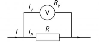
The photo shows a diagram of how the tester works when checking resistance. The terminals receive voltage of a certain type of polarity. “+” is supplied to the red terminal, “-” to the black terminal. When we touch, it turns out that there will be a positive probe at the anode terminal, and a negative one at the cathode terminal. Current will begin to flow through the diode.
If you mix up the probes, the current will not flow. The diode can be broken, serviceable, or broken. When a breakdown occurs, no matter which direction we connect the probes, current will flow through the diode. This is all because the diode in this case will be a piece of wire.
If a break occurs, no current will flow. It rarely happens that the junction resistance changes. Such a breakdown can be easily identified by looking at the display. Using this principle, you can check the rectifier diode, LED, zener diode, Schottky diode. Diodes can be either with leads or have an SMD design. Let's practice.
First, insert the probes into the device, observing the color markings. COM – black cable, R/V/f – red, plus. Next, set the slider to “dialing”. The photo shows the 2kOm position. We turn on the device, close the probes, and make sure that it works.
First of all, let's check the germanium diode D7. He is already 53 years old. Such diodes are not currently produced, since the price of raw materials is high, and the operating temperature is low (max 80-100). However, they are good because they have low noise and low voltage drop. They are appreciated by people who collect tube audio amplifiers.
When connected directly, the voltage drop is 0.129 mV. The dial gauge will show somewhere around 130 Ohms. If you change the polarity, the multimeter reading will be equal to 1, and the pointer, in turn, will show infinity. This means that the resistance is too great. The diode is OK.
A silicon based diode is tested in the same way. The case has 2 cathode terminals, which are marked with a dot, line or circle. With a direct connection, the drop is about 0.5 V. More powerful diodes will show approximately 0.4 V. Schottky diodes, whose drop is 0.2 V, are tested in this way.
Powerful LEDs have a drop of more than 2 V, the device can show 1. In this case, the LED is an indicator. If it glows, even faintly, then everything is fine.
Some types of higher-power LEDs are made according to the chain principle. That is, they have several LEDs connected in series. This is not visible from the outside. The drop across them can be up to 30 V; they should be checked with a power supply that has the appropriate voltage and resistors included in the circuit.
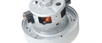
Checking electrolytic capacitors
Capacitors are divided into 2 types: electrolytic and simple. Simple ones are connected to the circuit in any way. But this method will not work with electrolytic ones. It is important to observe the polarity so as not to damage it.
Capacitors are shown on the diagram using two parallel lines. If the capacitor is electrolytic, you must indicate the polarity by placing a “+” sign next to it. Such capacitors are not reliable and most often they are the cause of failure of the power supply. A swollen capacitor in a device can often be noticed.
You can check such a capacitor with a multimeter or tester; in common parlance they say “ring.” Before starting the test, you need to unsolder the capacitors and discharge it. To do this, simply short-circuit its leads with tweezers or a similar object whose body is made of metal. The device should be set to test resistance in the range from hundreds of kilos to megaohms.
Use the probes to touch the terminals of the capacitor. At the same time, the arrow on the device will smoothly quickly deviate and smoothly fall. This depends on the size of the capacitor being tested. The larger the capacity, the slower the return of the arrow to its original position. The tester will show low resistance, but after a while it can reach hundreds of megohms.
If the readings differ from those described above and the resistance is zero, a breakdown is possible at the capacitor winding. When infinity is visible on the display, this indicates a break. This capacitor is not suitable for the application.
Classification and principle of operation
Classification
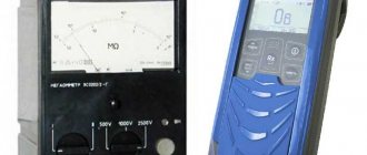
- According to their design, ohmmeters are divided into panel, laboratory and portable
- According to the principle of operation, ohmmeters can be magnetoelectric - with a magnetoelectric meter or magnetoelectric logometer (megaohmmeters) and electronic - analog or digital
Magnetoelectric ohmmeters
The operation of a magnetoelectric ohmmeter is based on measuring the current flowing through the measured resistance at a constant voltage of the power source, using a magnetoelectric microammeter. To measure resistances from hundreds of ohms to several megaohms, a meter (microammeter with additional resistance), a constant voltage source and the measured resistance rx
turn on in series.
In this case, the current strength I
in the meter is equal to:
I = U/(r0 + rx)
, where
U
is the voltage of the power source;
r0
is the resistance of the meter (the sum of the additional resistance and the resistance of the microammeter frame).
According to this formula, a magnetoelectric ohmmeter has a nonlinear scale. In addition, it is reverse (zero resistance value corresponds to the extreme right position of the instrument arrow). Before starting resistance measurement, it is necessary to perform a zero adjustment (adjust the value of r0
) a special regulator on the front panel when the input terminals of the device are closed, to compensate for instability of the power source voltage.
Since the typical value of the total deflection current of magnetoelectric microammeters is 50..200 μA, the supply voltage provided by the built-in battery is sufficient to measure resistances up to several megaohms. Higher measurement limits (tens - hundreds of megaohms) require the use of an external constant voltage source of the order of tens - hundreds of volts.
To obtain a measurement limit of kilo-ohms and hundreds of ohms, it is necessary to reduce the value of r0
and accordingly increase the total deflection current of the meter by adding a shunt.
At small values of rx
(up to several ohms) another circuit is used: the meter and
rx
are connected in parallel.
In this case, the voltage drop across the measured resistance is measured, which, according to Ohm's law, is directly proportional to the resistance (provided I
= const).
- EXAMPLES:
M419, M372, M41070/1
Ratiometric megohmmeters
The basis of ratiometric megaohmmeters is a ratiometer, to the arms of which exemplary internal resistors and the measured resistance are connected in different combinations (depending on the measurement limit), the reading of the ratiometer depends on the ratio of these resistances. As a source of high voltage necessary for carrying out measurements, such devices usually use a mechanical inductor - a manually driven electric generator; in some megohmmeters, a semiconductor voltage converter is used instead of an inductor.
- EXAMPLES:
ES0202, M4100
Analog electronic ohmmeters
The operating principle of electronic ohmmeters is based on converting the measured resistance into a voltage proportional to it using an operational amplifier. The measured object is included in the feedback circuit (linear scale) or at the input of the amplifier.
- EXAMPLES:
E6-13A, F4104-M1
Digital electronic ohmmeters
A digital ohmmeter is a measuring bridge with automatic balancing. Balancing is carried out by a digital control device by selecting precision resistors in the bridge arms, after which the measuring information from the control device is supplied to the display unit.
- EXAMPLES:
OA3201-1, E6-23, Shch34
Small resistance measurements. Four-wire connection
When measuring small resistances, an additional error may occur due to the influence of transition resistance at the connection points. To avoid this, use the so-called. four-wire connection method. The essence of the method is that two pairs of wires are used: one pair supplies a given current to the object being measured, and the other pair measures the voltage on the object, proportional to the current strength and resistance of the object. The wires are connected to the terminals of the two-terminal network being measured in such a way that each of the current wires does not directly touch the corresponding voltage wire, and it turns out that the transition resistances at the contact points are not included in the measuring circuit.
How to use a megohmmeter, measuring insulation
instrument.guru > Measuring > How to use a megohmmeter, insulation measurement
Electrical networks are characterized by various parameters. One of the most important parameters of networks is electrical insulation. Insulation is any material that prevents electrical current from flowing in the wrong direction.
Insulation can be the protective sheath of wires and cables. Devices such as insulators prevent conductive lines from contacting the ground.
All these measures to isolate conductive parts are aimed at preventing short circuits, fires, or electric shock to humans.
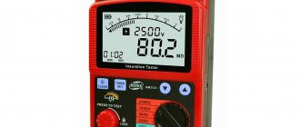
Megaohmmeter
Insulation, like any other material, is influenced by various external factors: weather, mechanical wear and others. For timely detection of insulation defects, there is a device, the so-called megohmmeter. It measures insulation resistance.
Operating principle of the device
What the device is intended for can be understood from its name, which is formed from three words: “mega” - the dimension of the number 106; “ohm” - a unit of resistance and “meter” - to measure.
To measure electrical resistance in the megohm range, a megohmmeter is used.
The principle of operation of the device is based on the application of Ohm's law, from which it follows that the resistance (R) is equal to the voltage (U) divided by the current (I) flowing through this resistance. Therefore, in order to implement this law in a device, you need:
- DC generator;
- measuring head:
- terminals for connecting the measured resistance;
- a set of resistors for operation of the measuring head within the working area;
- a switch that switches these resistors;
Implementation of a megohmmeter according to this scheme requires a minimum of elements. It is simple and reliable. Such devices have been working properly for half a century. The voltage in such devices is supplied by a direct current generator, the value of which varies in different models. Usually it is equal to 100, 250, 500, 700, 1000, 2500 volts.
Different models of devices may use one or more voltages from this series. Generators differ in power and, accordingly, in size. Such generators are operated manually.
To operate, you need to twist the handle of a dynamo, which produces direct current.
Working with a megohmmeter
Working on any equipment with this device is a high-risk job due to the fact that the device generates high voltage and there is a possibility of electrical injury.
Work with this device is permitted to be carried out by personnel who have studied the instructions for working with the device, in accordance with the rules of labor protection and safety precautions when working in electrical installations.
The employee must have the appropriate access group and periodically undergo tests on knowledge of the rules of work in electrical installations, know the instructions on labor protection, including the use of a megohmmeter.
Before starting work using a megohmmeter, you need to ensure the integrity of the device by visual inspection. There should be a verification stamp on it, there should be no chips on the device body, the indicator glass should be intact.
Test leads are checked for insulation damage. The device needs to be tested.
note
To do this, it is necessary, if a pointer instrument is used, to install it on a horizontal surface in order to avoid measurement errors and carry out measurements with open and closed probes.
On older models of megohmmeters, measurements are carried out by rotating the generator handle at a constant frequency of 120–140 rpm. On other models, measurements are made by pressing the corresponding button on the device. The megohmmeter should show infinity and zero megohms, respectively. After this, you can begin work on measuring insulation resistance.
Instrument measurements
The design of this type of work differs at different enterprises. In some organizations, this work is carried out according to a work permit, in others, by order or as part of routine operation. It is important that the general execution rules are the same.
Let’s take as an example the technology for measuring the insulation resistance of communication cables in railway transport.
Having completed all the necessary organizational and technical measures (designing the work, hanging posters, etc.), we proceed directly to the measurements.
Having selected the pair on which you want to measure, you first need to check that there is no voltage on it. Using the previously prepared ground electrodes, we remove the charge from the cable cores being measured and ground them.
Having installed the measuring probes and removed the ground electrodes, we measure the insulation resistance with a megohmmeter.
Having recorded the results obtained, switch the measuring probe to another core and repeat the measurement procedure.
It must be remembered that after measurements are taken, an electrical charge remains in the cable. After completing the measurements, it is necessary to remove the electrical charge using a grounding electrode. It is necessary to discharge the megohmmeter itself. This is done by short-circuiting the measuring cords to each other. Work on installing measuring probes and grounding conductors is carried out wearing dielectric gloves.
Important
The measured value of insulation resistance is entered into the protocol. The protocol usually indicates which device used the measurement, the magnitude of the applied voltage and the measured insulation resistance. The amount of resistance varies for different types of tests. It is compared with the permissible value and a conclusion is drawn about the state of the insulation of the electrical installation.
Names and designations
Species names
- Microohmmeter
- ohmmeter with the ability to measure very low resistances (less than 1 mOhm) - Milliohmmeter
- ohmmeter for measuring small resistances (units - hundreds of milliohms) - Megaohmmeter
(
old
megohmmeter) - ohmmeter for measuring high resistances (units - hundreds of megaohms) - Teraohmmeter
- ohmmeter for measuring very high resistances (units - hundreds of teraohms) - Ground resistance meter
- a special ohmmeter for measuring transient resistance in grounding devices
Designations
Ohmmeters are designated either depending on the system (basic operating principle) or according to GOST 15094
- M
xx - devices of the magnetoelectric system - F
xx,
Shch
xx - electronic system devices - E6-
xx - resistance meters, marking according to GOST 15094
Types of electrical measuring instruments
Classification of electrical measuring instruments:
By type of current:
- variable;
- permanent;
- combined devices.
By level of accuracy:
- 0, 05;
- 0,1;
- 0,2;
- 0,5;
- 1,0.
Each number indicates a percentage of the permissible error.
According to the essence of the work:
- electromagnetic;
- induction;
- magnetoelectric;
- ferromagnetic.
When carrying out measurement tests, it is necessary to select the appropriate measuring device correctly.
- Ammeters are devices for measuring current values. The unit of measurement is Ampere (A).
- Voltmeter – measures the voltage of the electrical network. The unit of measurement is Volt (V).
- An ohmmeter is an auxiliary device that measures resistance in an electrical circuit. Measured in Ohms (Ohm).
- A wattmeter is an element that measures network power. The unit measured is Watt (W).
- Frequency meter – a frequency meter for alternating pulse values. Measured in Hertz (Hz).
Other resistance measuring instruments
DC resistance measurement
- Measuring bridge
- provides very high accuracy, but is inconvenient due to the need for manual balancing - Resistance store
,
electrical resistance coils
- measurement is carried out by comparison method, using substitution of the measured object - Multimeter (tester)
- a combined device for measuring voltage, current and resistance
AC resistance measurement
- Immittance meter
- resistance measurements at frequencies from tens of hertz to several megahertz - High-frequency (vector) impedance meter
- resistance measurements at frequencies of hundreds of kilohertz - hundreds of megahertz - Q meter
- indirect resistance measurements at frequencies from 1 kHz to several hundred megahertz - Impedance meter
- measuring line load resistance at frequencies of tens - hundreds of megahertz - Measuring line
- measuring line load resistance at frequencies of hundreds - thousands of megahertz
How to use a multimeter?
Friends, hello everyone! Today I bought a multimeter and wanted to tell you a few words about this device, what it is for and how to use it. A multimeter is a combined electrical measuring device that combines several functions.
includes functions of a voltmeter (for measuring voltage ), ammeter (for measuring current ) and ohmmeter (for measuring resistance ), has continuity functions and functions for measuring temperature with a thermocouple.
Sometimes a multimeter is made in the form of a clamp meter. There are digital and analog multimeters.
Important
I purchased a multi-meter with temperature measurement and sound testing. Before starting work, insert the black probe into the lowest socket of the device labeled COM), and the red probe into the middle one. When measuring the current, we move the red probe to the upper socket.
1. So let's start by measuring the voltage. Voltage, as we know, can be constant or variable . Constant voltage includes batteries, accumulators, and chargers.
We will measure using a regular battery. We know in advance that the voltage is 1.5 volts, so we select the range accordingly.
Literature and documentation
Literature
- Handbook of Electrical Measuring Instruments
; Ed. K. K. Ilyunina - L.: Energoatomizdat, 1983 - Handbook of radio measuring instruments
: In 3 volumes; Ed. V. S. Nasonova - M.: Sov. radio, 1979 - Handbook of Electrical Measuring Instruments
; Ed. K. K. Ilyunina - L., 1973
Regulatory and technical documentation
- GOST 22261-94 “Instruments for measuring electrical and magnetic quantities. General technical conditions"
- GOST 23706-93
- GOST 8.366-79 “State system for ensuring the uniformity of measurements. Digital ohmmeters. Methods and means of verification"
- GOST 8.409-81 “State system for ensuring the uniformity of measurements. Ohmmeters. Methods and means of verification"
see also
- Electrical resistance
- Measuring bridge
- Resistance Shop
- Imitance meter
- Q meter
- Impedance meter
- Measuring device
- Radio measuring instruments
- Electrical measuring instruments
- Unplug and turn off the power to the circuit under test.
To ensure measurement accuracy, as well as your own safety, the wire or circuit must be completely de-energized. Your ohmmeter will provide voltage and current to the circuit, so there is no need for other power sources. According to the ohmmeter/voltmeter instructions, testing a circuit while power is present “can cause damage to the meter, the circuit, and you.”
- Choose the right ohmmeter for your project.
Analog ohmmeters are very easy to use and inexpensive. Their measuring range is from 0-10 to 0-10,000 ohms. Digital analogues have the same range or "auto-ranging", so they can measure the resistance of a device or circuit and automatically select the appropriate range.
- Check the ohmmeter for battery presence.
If you just recently purchased an ohmmeter, the battery may already be installed in the meter or packaged separately along with installation instructions.
- Insert the probes into the connectors on the device.
For multi-function appliances, you will see a "common" or negative probe, as well as a "positive" probe. They also come in different colors, red (+) and black (-).
- Zero the instrument if it has a zero dial.
Note that the scale moves in the opposite direction of most conventional measuring scales, meaning more resistance on the right and less resistance on the left. Zero resistance will be observed when connecting two probes to each other. You can adjust the meter by holding the probes together and turning the dial until the needle on the scale reads 0 ohms.
- Select the circuit or electrical device you want to test.
To practice, you can take almost anything that conducts electricity, from a piece of aluminum foil to a pencil mark on paper. To get an idea of the accuracy of your measurements, go to an electronics store and buy several different resistors or devices with a known resistance level.
- Touch one probe to one edge of the circuit, and the other to the other edge and look at the indicators of the device.
If you purchased a 100 ohm resistor, you can touch each wire on the resistor with a probe, select the 1000 or 10,000 ohm range, and read the meter to make sure it actually reads 1000 ohms.
- Isolate components in a heavy-duty electrical circuit to test them separately from each other.
If you are reading ohms across a resistor in a PCB, you will have to unsolder or chip off the resistor to be sure you are not getting a false reading from another part of the circuit.
- Measure the resistance of the wires or circuit line to check for a short or open open in the circuit.
If you get an "infinite resistance" reading, it means there is nowhere for the electrical current to go. Simply put, this indicates a burned out component somewhere in the circuit or a broken conductor. Since most circuits contain "output" devices (transistors and semiconductors), diodes and capacitors, you may not be able to measure continuity even if the circuit is completely intact. This is why it is very difficult to test a circuit with just an ohmmeter.
- If you are not using the ohmmeter, turn it off.
Sometimes, while storing the device, the wires can become shorted and cut off power to the battery.
Voltage measurement
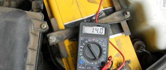
Voltage measurement has been and remains one of the most popular measurements in everyday life. The charge of the battery is measured by motorists, and the voltage in the network is checked during interruptions in the operation of electrical appliances.
Considering that voltage is the potential difference between two points, to determine the alternating voltage, the probes of the device must be connected in parallel to the device whose voltage is being assessed.
How to measure voltage, for example, of a battery:
- Connect the probes.
- Set the switch to the maximum value in the ACV sector.
- Holding the probes by their insulated areas, touch the bare ends to the different contacts of the battery.
- Record the measurement results in volts displayed on the screen.
- If the readings are not accurate, you should change the limit measurement value by moving the switch knob to the optimal value from the suggested range.
To measure DC voltage, set the switch knob to the DCV sector (voltmeter mode). It is not necessary to maintain the polarity as a negative value will be displayed on the screen if connected in reverse.