Now EMF and voltage are perceived by many as identical concepts, which, even if they have some distinctive features, are so insignificant that they hardly deserve your attention.
On the one hand, this state of affairs takes place, because those aspects that distinguish these two concepts are so insignificant that even more or less experienced users are unlikely to notice them. However, they are still provided and it is also impossible to say that the EMF and voltage are exactly the same.
What is voltage
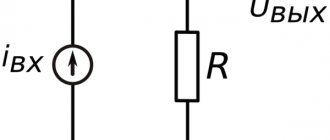
Electric voltage (denoted as U) is a physical quantity that reflects the quantitative characteristic of the work of the electric field in transferring charge from point A to point B. Accordingly, the voltage can be between two points of the circuit, but unlike EMF, it can be between two terminals of which something from the elements of the circuit. Let us recall that EMF characterizes the work performed by external forces, that is, the work of the current source itself or the EMF to transfer charge through the entire circuit, and not on a specific element.
This definition can be expressed in simple language. The voltage of direct current sources is the force that moves free electrons from one atom to another in a certain direction.
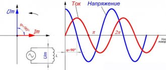
For alternating current the following concepts are used:
- instantaneous voltage is the potential difference between points in a given period of time;
- amplitude value – represents the maximum absolute value of the instantaneous voltage value over a period of time;
- average value – constant voltage component;
- RMS and RMS.
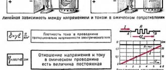
The voltage of a circuit section depends on the conductor material, load resistance and temperature. Just like electromotive force is measured in Volts.
Often, to understand the physical meaning of tension, it is compared to a water tower. A column of water is identified with voltage, and a flow with current.
At the same time, the column of water in the tower gradually decreases, which characterizes a decrease in voltage and a decrease in current.
Are emf and voltage the same thing? If not, can you provide a simple explanation of what they represent?)))
Electromotive force and voltage
To maintain an electric current in a conductor, some external source of energy is needed, which would always maintain a potential difference at the ends of this conductor. Such energy sources are the so-called sources of electric current, which have a certain electromotive force that creates and maintains a potential difference at the ends of the conductor for a long time.
Electromotive force (abbreviated EMF) is denoted by the letter E. The unit of measurement for EMF is the volt. In our country, the volt is abbreviated as “B”, and in the international designation it is abbreviated as “V”.
So, to obtain a continuous flow of electric current, you need an electromotive force, that is, you need a source of electric current.
The first such current source was the so-called “voltaic column”, which consisted of a series of copper and zinc circles lined with leather soaked in acidified water. Thus, one of the ways to obtain electromotive force is the chemical interaction of certain substances, as a result of which chemical energy is converted into electrical energy. Current sources in which electromotive force is created in this way are called chemical current sources.
Currently, chemical current sources - galvanic cells and batteries - are widely used in electrical engineering and power engineering. Another main source of current, widely used in all areas of electrical engineering and power engineering, are generators.
Current sources are used to supply electric current to various devices - current consumers. Current consumers are connected using conductors to the poles of the current source, forming a closed electrical circuit. The potential difference that is established between the poles of a current source in a closed electrical circuit is called voltage and is designated by the letter U.
The unit of measurement for voltage, like EMF, is the volt.
If, for example, it is necessary to write down that the voltage of the current source is 12 volts, then they write: U - 12 V.
To measure EMF or voltage, a device called a voltmeter is used.
The EMF developed by a current source is always greater than the voltage at its terminals.
Source
So what's the difference
To better understand the difference between electromotive force and voltage, let's look at an example. There is a source of electrical energy of infinite power, in which there is no internal resistance. A load is mounted in the electrical circuit. In this case, the statement will be true that the EMF and voltage are identically equal, that is, there is no difference between these concepts.
However, these are ideal conditions that do not occur in real life. These conditions are used exclusively for calculations. In real life, the internal resistance of the power supply is taken into account. In this case, the EMF and voltage are different.
The figure shows what the difference will be in the values of electromotive force and voltage in real conditions. The above formula for Ohm's law for a complete circuit describes all processes. When the circuit is open, the battery terminals will have a value of 1.5 Volts. This is the EMF value. By connecting the load, in this case it is a light bulb, it will have a voltage of 1 volt.
The difference from an ideal source lies in the presence of internal resistance of the power supply. It is at this resistance that the voltage drop occurs. These processes are described by Ohm's law for a complete circuit.
If the measuring device at the terminals of the electricity source shows a value of 1.5 Volts, this will be electromotive force, but we repeat, assuming there is no load.
When connecting a load, the terminals will have a lower value. This is tension.
EMF. Ohm's law for a complete circuit
The author of the article is a professional tutor, author of textbooks for preparing for the Unified State Exam Igor Vyacheslavovich Yakovlev
Topics of the Unified State Examination codifier: electromotive force, internal resistance of a current source, Ohm's law for a complete electrical circuit.
Until now, when studying electric current, we have considered the directional movement of free charges in an external circuit
, that is, in the conductors connected to the terminals of the current source.
As we know, positive charge:
• goes into the external circuit from the positive terminal of the source;
• moves in an external circuit under the influence of a stationary electric field created by other moving charges;
• comes to the negative terminal of the source, completing its path in the external circuit.
Ohm's law for a complete circuit
After reducing by we get:
So we found the current in the circuit:
Formula (4) is called Ohm's law for a complete circuit
.
Due to the small internal resistance, the short circuit current can be quite large. For example, a AA battery gets so hot that it burns your hands.
Knowing the current strength (formula (4)), we can find the voltage across the resistor using Ohm’s law for a section of the circuit:
This voltage is the potential difference between points and (Fig. 2). The potential of the point is equal to the potential of the positive terminal of the source; the potential of the point is equal to the potential of the negative terminal. Therefore, voltage (5) is also called voltage at the source terminals
.
The meaning of this result is simple: if the source is not connected to the circuit, then a voltmeter connected to the poles of the source will show its EMF
.
Third party force
Nevertheless, current flows through the circuit; therefore, there is a force that “pulls” the charge through the source despite the resistance of the electric field of the terminals (Fig. 1).
Rice. 1. Third party force
This force is called a third party force
;
It is thanks to it that the current source functions. The external force has nothing to do with the stationary electric field - it is said to be of non-electrical
origin; in batteries, for example, it arises due to the occurrence of appropriate chemical reactions.
Let us denote by the work of an external force to move a positive charge q inside the current source from the negative terminal to the positive. This work is positive, since the direction of the external force coincides with the direction of charge movement. The work of an external force is also called the work of a current source
.
There is no external force in the external circuit, so the work done by the external force to move the charge in the external circuit is zero. Therefore, the work of an external force to move a charge around the entire circuit is reduced to the work of moving this charge only inside the current source. Thus, this is also the work of an external force to move charge throughout the circuit
.
We see that the external force is non-potential - its work when moving a charge along a closed path is not zero. It is this non-potentiality that allows the electric current to circulate; a potential electric field, as we said earlier, cannot support a constant current.
This quantity is called electromotive force
(EMF) of the current source. As you can see, EMF is measured in volts (V), so the name “electromotive force” is extremely unfortunate. But it has long been ingrained, so you have to come to terms with it.
When you see the inscription on the battery: “1.5 V”, then know that this is exactly the EMF. Is this value equal to the voltage created by the battery in the external circuit? It turns out not! Now we will understand why.
Electromagnetic induction (self-induction)
Let's start with electromagnetic induction. This phenomenon is described by Faraday's law of electromagnetic induction. The physical meaning of this phenomenon is the ability of an electromagnetic field to induce an emf in a nearby conductor. In this case, either the field must change, for example, in the magnitude and direction of the vectors, or move relative to the conductor, or the conductor must move relative to this field. In this case, a potential difference arises at the ends of the conductor.
There is another phenomenon that is similar in meaning - mutual induction. It lies in the fact that a change in the direction and current strength of one coil induces an EMF at the terminals of a nearby coil; it is widely used in various fields of technology, including electrical and electronics. It underlies the operation of transformers, where the magnetic flux of one winding induces current and voltage in the second.
In electrical engineering, a physical effect called EMF is used in the manufacture of special AC converters that provide the required values of effective quantities (current and voltage). Thanks to the phenomena of induction and self-induction, engineers have been able to develop many electrical devices: from a conventional inductor (inductor) to a transformer.
The concept of mutual induction refers only to alternating current, the flow of which in a circuit or conductor changes the magnetic flux.
An electric current of constant direction is characterized by other manifestations of this force, such as, for example, a potential difference at the poles of a galvanic cell, which we will discuss later.
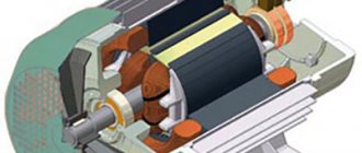
Electric motors and generators
The same electromagnetic effect is observed in the design of an asynchronous or synchronous electric motor, the main element of which is inductive coils. His work is described in accessible language in many textbooks related to the subject called “Electrical Engineering”. To understand the essence of the processes taking place, it is enough to remember that the induced emf is induced when a conductor moves inside another field.
According to the law of electromagnetic induction mentioned above, a counter EMF is induced in the armature winding of the motor during operation, which is often called “back EMF” because when the motor is running it is directed towards the applied voltage. This also explains the sharp increase in current consumed by the motor when the load increases or the shaft is jammed, as well as starting currents. For an electric motor, all the conditions for the appearance of a potential difference are obvious - a forced change in the magnetic field of its coils leads to the appearance of torque on the rotor axis.
In another electrical device - a generator, everything is exactly the same, but the processes occurring in it have the opposite direction. An electric current is passed through the rotor windings, and a magnetic field arises around them (permanent magnets can be used). When the rotor rotates, the field, in turn, induces an EMF in the stator windings - from which the load current is removed.
A little more theory
When designing such circuits, the current distribution and voltage drop across individual elements are taken into account. To calculate the distribution of the first parameter, Kirchhoff's second law, known from physics, is used - the sum of the voltage drops (taking into account the sign) on all branches of a closed circuit is equal to the algebraic sum of the EMF of the branches of this circuit), and to determine their values, Ohm's law for a section of the circuit or Ohm's law is used for a complete chain, the formula of which is given below:
I=E/(R+r),
where E is the EMF, R is the load resistance, r is the resistance of the power source.
The internal resistance of a power source is the resistance of the windings of generators and transformers, which depends on the cross-section of the wire with which they are wound and its length, as well as the internal resistance of galvanic cells, which depends on the state of the anode, cathode and electrolyte.
When carrying out calculations, it is necessary to take into account the internal resistance of the power source, considered as a parallel connection to the circuit
A more accurate approach, taking into account large values of operating currents, takes into account the resistance of each connecting conductor
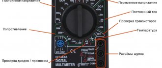
How to determine the value of alternating voltage in the network
An important point when determining alternating voltage is that the multimeter probes are connected in parallel to the device being measured. This is because voltage itself represents the potential difference between two points.
The same principle can be used as in the case of alternating current. Adjust the range of values from maximum to minimum, keeping in mind the position of the sensors.
For example, you can use a standard battery to measure AC voltage. The switch is set to the appropriate mode, the interval is set. In this case, the probes touch the battery in parallel on both sides. And you can immediately see how the voltage value of the element under study is displayed on the screen.
The situation is the same with constant voltage, but you just need to remember to set the switch to the correct mode.
Regardless of the model and specific operation of the multimeter, it is important to follow fire safety rules and handle electrical devices correctly without endangering your health.
EMF in everyday life and units of measurement
Other examples can be found in the practical life of any ordinary person. Common things like small batteries and other miniature batteries fall into this category. In this case, the working EMF is formed due to chemical processes occurring in constant voltage sources.
When this happens at the terminals (poles) of the battery due to internal changes, the cell is fully ready for use. Over time, the EMF decreases slightly, and the internal resistance increases significantly.
As a result, if you measure the voltage on an unconnected finger battery, you will see 1.5V (or so) is normal, but when there is a load connected to the battery - say you installed it in some device - it does not work.
Why? Because if we assume that the internal resistance of the voltmeter is many times greater than the internal resistance of the battery, then you have measured its emf. When the battery began to supply current to the load, its terminals became not 1.5 V, but, for example, 1.2 V - the device does not have enough voltage or current for normal operation. It was this 0.3V that reached the internal resistance of the galvanic element. If the battery is very old and its electrodes are destroyed, there may be no electromotive force or voltage, such as zero, at the battery terminals.