One of the parameters that characterizes the state of the electrical network is its power.
It reflects the amount of work performed by electric current per unit of time. The power of devices included in the electrical circuit must be within the power of the network. Otherwise, unpleasant surprises are possible - from equipment failure to short circuits and fires. The power of electric current is measured with a special device - a wattmeter. And if in a DC circuit it is calculated by simply multiplying the current by voltage (a voltmeter and an ammeter are sufficient), then in an AC network you cannot do without measuring equipment. They also control the operating mode of electrical equipment and take into account energy consumption.
Application of Wattmeters
The main area of application is the electrical power industry and mechanical engineering, electrical appliance repair shops. However, household meters are also widely used, which are purchased by lovers of electronics, computers and just ordinary people - to account for and save energy consumption.
Wattmeters are used for:
- Determining the power of devices;
- Testing of electrical networks and their individual sections;
- Testing of electrical installations (as indicating devices);
- Monitoring the operation of equipment;
- Accounting for electricity consumption.
Types of wattmeters
Power measurement is preceded by measuring the current and voltage of the test section of the circuit.
Depending on the methods of measurement, data conversion and display of final information, wattmeters are divided into analog and digital.
Analog wattmeters are either indicating or recording and reflect the active power of a circuit section. The display of the indicating device has a semicircular scale and a rotating arrow. The scale divisions are graduated according to specific power values, measured in watts (W).
Digital wattmeters measure both active and reactive power. In addition, the device display can also display (in addition to power readings) current, voltage, and energy consumption over time. Measurement data can be displayed remotely on the operator’s computer.
Video about a wattmeter from China:
Reactive power is measured using a special varmeter device; it can also be determined indirectly using a number of devices such as a voltmeter, ammeter, and phase meter.
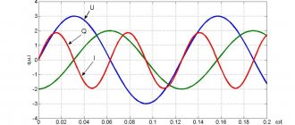
Reactive power is a quantity characterizing the loads created on electrical equipment by changes in the energy of the electromagnetic field in alternating current circuits:
Q = UIsin φ
The unit of measurement of reactive power is reactive volt-ampere (var). Reactive power in electrical networks causes additional active losses and voltage drop . In special-purpose electrical installations (induction furnaces), reactive power is significantly greater than active power. This leads to an increase in the reactive component of the current and causes overload of power supply sources. To eliminate overloads and increase the power factor of electrical installations, reactive power compensation is carried out.
NEED A CONSULTATION?
Call:
+7 (495) 730-73-62, +7, +7
Write:
or fill out a simple form
To correctly determine the required power value of the reactive power compensation installation, it is necessary to take measurements in the electrical network.
The use of modern electrical measuring instruments based on microprocessor technology allows for a more accurate assessment of the amount of energy in the network.
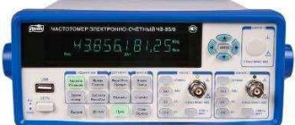
The energy quality and consumer network parameters analyzer is a universal measuring system designed for measuring, storing in memory and monitoring electrical parameters in low and medium voltage power networks. Measurement is carried out in single-phase and three-phase networks. One of the main advantages of the analyzer of energy quality and consumer network parameters is the high accuracy of measurements, compact dimensions and the ability to measure harmonics of current and voltage in the network. One analyzer of energy quality and consumer network parameters combines 13 different measuring instruments: ammeter, voltmeter, wattmeter, reactive and apparent power meters, power factor cos φ, frequency meter, harmonic analyzer of current and voltage, meters of active, reactive and total consumed electricity. The three-phase electronic measuring system of the device measures and digitizes the effective values of voltage and current in a three-phase network with a frequency of 50/60 Hz. The device takes 2 measurements within a second. From the obtained values, the microprocessor calculates the electrical parameters. Maximum, minimum parameter values and program data are stored in memory. Selected measured values, as well as data on network interruptions, are stored in a buffer memory with date and time. Then this information can be viewed and analyzed on a computer monitor or printed on a printer.
NEED A CONSULTATION?
Call:
+7 (495) 730-73-62, +7, +7
Write:
or fill out a simple form
Device and principle of operation
Analog wattmeters
The most common and accurate analog wattmeters are electrodynamic system devices.
The operating principle is based on the interaction of two coils. One of them is stationary, has a thick winding with a small number of turns and low resistance. Connected in series with the load. The second coil is movable.
Its winding is made of thin wire and has a large number of turns, so its resistance is high.
It is connected in parallel to the load and is equipped with additional resistance (to prevent a short circuit between the coils).
When the device is connected to the network, magnetic fields are formed in the coils. Their interaction creates a torque that deflects the moving coil with the arrow connected to it at a certain angle.
The magnitude of the angle is equivalent to the product of current and voltage at a given time.
Digital wattmeters
The operation of a digital wattmeter is based on a preliminary measurement of current and voltage. To do this, the following are installed at the input: in series with the load - a current sensor, in parallel - a voltage sensor. They can be based on thermistors, instrument transformers, thermocouples and other elements.
The instantaneous values of the obtained current and voltage values are transmitted through an analog-to-digital converter to the built-in microprocessor. Here the necessary calculations are made (active and reactive power is found) and are presented as final information on the display and connected external devices.
Figure - Wattmeter connection diagram
GENERAL INFORMATION AND CLASSIFICATION OF METHODS AND DEVICES FOR POWER MEASUREMENT
POWER MEASUREMENT
In the practice of electroradio measurements, the task of measuring power has to be encountered in almost the entire frequency range used - from low-frequency direct and alternating current to the optical range. In low frequency DC and AC circuits, power is measured directly or indirectly using electromechanical instruments. At high frequencies (HF), direct power measurement becomes preferable and more accurate, and at ultra-high frequencies (UHF) this is the only type of measurement that unambiguously characterizes the intensity of electromagnetic oscillations.
ABSORBED POWER MEASUREMENT AT HIGH AND ULTRA-HIGH FREQUENCIES
Absorbed power measurements are most common at RF and microwave. Primary converters of absorbed power wattmeters are the equivalent of a matched load and, as can be seen from Fig. 4.1, a, are switched on at the end of the transmission line. Most of the methods listed in § 4.1 can be used to measure absorbed power.
THERMAL METHODS
Thermal methods are based on the conversion of electromagnetic energy into thermal energy and then measuring the amount of heat released (temperature increase) or the replacement DC power (low frequency) causing an equivalent temperature increase. The main advantage of thermal wattmeters is the ability to calibrate and certify them using direct current, which helps achieve high accuracy in power measurement.
Calorimetric method
The calorimetric method is one of the most accurate methods for measuring power at RF and microwave. The design of calorimetric wattmeters is very diverse and is determined by the level of measured power, frequency range and required accuracy. However, in all cases, the primary converter of the wattmeter is the calorimeter,
where the conversion of electromagnetic energy into thermal energy takes place. All calorimeters are divided into calorimeters with variable and constant temperature.
Variable calorimeters
temperature can be structurally designed as static and flow-through.
In static calorimeters, the working fluid, where electromagnetic energy is converted into thermal energy, is motionless and does not change its shape or physical properties during the measurement process. The working fluid can be water and solid (volumetric or film) absorbers. In the first case, the calorimeter is a Dewar vessel, and calorimeters with solid absorbers are called “dry”. Dry calorimeters are the most common and are structurally coaxial (Fig. 4.3, a)
or waveguide (Fig. 4.3,
b)
matched loads, in which the increase in temperature of the working fluid is measured using thermocouples.
Calibration in such calorimeters is carried out by direct current, which passes either directly through the load (microwave resistor in Fig. 4.3, a) or through a special heater (winding in Fig. 4.3, b).
Rice. 4.3. Schematic structure of a dry calorimeter:
a - coaxial: 1 - internal conductor; 2 - external conductor; 3 - microwave resistor; 4 — screen; b - waveguide; 1 - waveguide; 2 — screen; 3 - heater; 4—absorber.
In flow calorimeters, the working fluid is a circulating fluid, and the process of measuring power is reduced to measuring the temperature increment and flow rate of this fluid. Such calorimeters can also be coaxial (Fig. 4.4, a) and waveguide (Fig. 4.4,6).
The liquid used is water, silicon-organic liquid, etc.
Rice. 4.4. Schematic design of a flow calorimeter:
a — coaxial: 1—dielectric washer; 2—load housing; b—waveguide: /—load housing; 2 - dielectric wedge.
The second group of calorimeters are calorimeters with a constant
temperature - currently represented by phase change calorimeters, compensation calorimeters and calorimeters based on the substitution method.
In phase change calorimeters, the electromagnetic energy converted to thermal energy is determined by the amount of solid matter (such as ice) converted to a liquid state. In compensation calorimeters, the processes of heat release and equivalent absorption occur simultaneously and at the same speed. Calorimeters based on the substitution method are characterized by preheating of the working fluid using direct or alternating current. After Px
, the thermal regime of the working fluid is maintained unchanged by reducing the heating power, and the value
of Px
is determined by the change in this power.
In the DI of calorimetric wattmeters, both the direct conversion method by measuring the temperature increment of the working fluid, and the comparison method by measuring the replacement power of direct or alternating current can be implemented. Direct conversion calorimetric wattmeters are almost never used due to low sensitivity and low accuracy. Let us therefore consider a calorimetric wattmeter with a flow calorimeter that implements the comparison method.
Rice. 4.5. Block diagram of a calorimetric wattmeter with a flow calorimeter
.
As can be seen from Fig. 4.5, during the measurement process, a comparison is made of the thermal effect of the measured power Px,
supplied to the primary converter
I,
with the thermal effect of the DC power supplied to the reference load
4.
The process of measuring the replacement power is automated thanks to a closed circulation system.
The working and support loads are sequentially washed by one fluid flow, and due to the heat exchanger 5
, equality of fluid temperatures at the inputs of both loads is ensured.
The design of the loads provides for the placement of thermistors 2 and 3,
which together with resistors R1
and
R2
form
In the absence of Px,
the temperature of the thermistors is the same and the bridge is balanced.
After applying Px
, the bridge is unbalanced, and the unbalance signal is sent through an AC amplifier to the detector, where it is converted into a DC compensation voltage.
This voltage is supplied to the reference load through the UPT and is simultaneously measured by a magnetoelectric device. As a result of a change in the temperature of the reference load, the resistances of the thermistors are equalized, the balance of the bridge is restored, and the reading of the device turns out to be proportional to the measured value of Px.
Thus, we obtain a direct-reading calorimetric wattmeter with automatic thermal balancing.
The main advantages of calorimetric wattmeters are an exceptionally wide frequency range, wide limits and high measurement accuracy, determined mainly by the measurement error of the replacement power (compensation voltage) and operating load parameters, which are precisely known for each wattmeter. Therefore, on the basis of the calorimetric method, state special standards for the unit of power of electromagnetic oscillations in coaxial and waveguide paths have been developed, approved by GOST 8.073-73, GOST 8.102-73 and GOST 8.277-78. They provide watt reproduction with a standard deviation of no more than 0.15% and a non-excluded systematic error not exceeding 0.5%. Disadvantages of calorimetric wattmeters: large inertia (the time it takes to establish readings can reach several minutes) and difficulty in operation.
Thermoelectric method
The thermoelectric method is based on converting microwave energy into thermal energy using thermocouples and measuring the resulting thermoEMF ET,
proportional to the microwave power dissipated in the thermocouple. Thus, thermocouples simultaneously perform (unlike a dry calorimeter) the functions of a matched load and a thermometer.
The thermoelectric method, like the bolometric method, is applicable to measuring low power levels. However, it has a significant advantage over the bolometric one: the ET
practically independent of ambient temperature, and there is no need for special thermal compensation circuits. In addition, thermocouples do not require initial heating, have high sensitivity and, together with a simple DUT, make it possible to implement direct conversion thermoelectric wattmeters.
Rice. 4.10. Equivalent circuit of a thermoelectric converter with differential connection of thermocouples.
Rice. 4.11. Amplitude characteristic of thermoelectric converter.
The design of coaxial and waveguide-type thermoelectric heads is generally similar to the design of bolometric heads (see Fig. 4.7 and 4.8). To increase the sensitivity, thermocouples are made differential, with direct current branches of the thermocouple connected in series, and high frequency branches in parallel. As can be seen from the equivalent circuit in Fig. 4.10, this is achieved using a design capacitor C2. Capacitor C1 (also structural) allows you to decouple DC and microwave circuits. The values of RT1 and RT2 are selected from the head matching condition. Film thermocouples (metal films deposited on dielectric substrates) are mainly used, and the most widely used thermocouples are bismuth - antimony, kopel - antimony and chromel - kopel.
The main characteristic of a thermoelectric converter is the amplitude characteristic ET(РХ),
a typical view of which is shown in Fig.
4.11. The linear portion of the characteristic determines the limits of Px measurement,
and the characteristics of differential thermocouples have maximum linearity.
Since the output signal of the converter is a direct voltage, the DUT of thermoelectric wattmeters is a direct current voltmeter, the scale of which is graduated in Px values.
In practical wattmeter circuits, both analog and digital voltmeters are used. An additional functional unit of the IU is a power calibrator—a stabilized square wave generator with a frequency of 20...50 kHz. It is used to calibrate the wattmeter before starting work and after changing the converter. Thanks to this, the spread of ET(PX) characteristics is eliminated.
The main advantages and parameters of thermoelectric wattmeters are the same as those of bolometric (thermistor) ones. An additional important advantage, as already noted, is the low dependence of the measurement results on the ambient temperature. The main disadvantage of wattmeters is their small measurement limits and low resistance to overloads.
ELECTRONIC METHODS
Common to electronic methods is the conversion of the measured power into a proportional DC or AC voltage and then measurement of this voltage. The main advantage of these methods is their low inertia, due to which they allow direct measurement of RI. In absorbed power wattmeters, as a rule, the voltmeter method and the method using the effect of “hot” current carriers are implemented.
Voltmeter method
The voltmeter method, also called the method of measuring voltage across a known resistance, is very simple and consists of using a voltmeter to measure the voltage across a resistor connected as a load at the end of the transmission line. Since the load must be matched to a transmission line having characteristic impedance W, the value of Px can be determined from the voltmeter readings as ,
,
or if the detector is peak (when measuring, for example,
RI).
Rice. 4.12. Schematic design of the load and detector of an electronic wattmeter.
The main difficulties in implementing the method and sources of errors are associated with the design and coordination of the load and the voltmeter detector. To expand the frequency range, the detector is structurally combined with a load, as shown schematically in Fig. 4.12, removing the voltage either from the entire resistor or from part of it. In practice, both semiconductor and vacuum detectors are used (when measuring high powers). Semiconductor diodes in combination with film microwave resistors provide a frequency range of wattmeters up to 40 GHz.
The main advantages of the method are the simplicity and high reliability of wattmeters, as well as the ability to measure small and large values of P
and
Ri.
However, the measurement error can reach ±25%.
ABSORBING WALL METHOD
The absorbing wall method is a thermal method, but unlike the case of measuring absorbed power, only part of the power passing into the load is converted into heat. Structurally, this is achieved by constructing one of the sections of the path in the form of a temperature-sensitive resistive element with losses. In the simplest case, such an element (entracometer) is an absorbing platinum film built into the side wall of the waveguide (Fig. 4.14). Similar to the bolometer, the entracommeter is included in the bridge circuit (see Fig. 4.9), with the help of which the value of the power absorbed by the entracommeter is measured, and the value of Rpr is determined using a formula similar to (4.16). To ensure thermal compensation, a similar film is placed on the outside of the waveguide, which is also included in the bridge circuit.
Wattmeters with conventional entracometers allow the measurement of low and medium power levels. In high-power wattmeters, the outer surface of the enthracometer is cooled by a flowing liquid, the flow of which is taken into account when determining Rpr. The result is simple and reliable wattmeters for built-in control of RPR in a wide frequency range. Their disadvantages are significant measurement errors (reaching ±25%) and inertia.
Rice. 4.14. Schematic design of an entracommeter.
PONDEROMOTOR METHOD
The ponderomotive power measurement method is based on the conversion of electromagnetic energy into mechanical energy. This conversion in turn uses the well-known effect of mechanical (ponderomotive) action (pressure) of electromagnetic waves on the walls of the transmission line or on reflective elements located inside the line. Mechanical pressure is proportional to the modulus of the Umov-Poynting vector perpendicular to the reflecting surface. There are two main ways to practically implement the ponderomotive method.
In wattmeters using the first method, part of the side wall of the waveguide is replaced by an elastic plate - a microwave membrane, which is deformed under the influence of the RPR. A piezoelectric element or a capacitor element can be used to measure the degree of deformation. In this case, the upper limit of measured powers
Rice. 4.16. Schematic design of a torsional wattmeter.
is practically limited only by the electrical strength of the waveguide.
Wattmeters that implement the second method are called torsional. As can be seen from Fig. 4.16, structurally such a wattmeter is a section of a waveguide, inside of which a metal plate is placed 1,
suspended on an elastic quartz thread
2, and on
the other hand fixed on a rigid rod
4,
the second end of which is lowered into an oil shock absorber 7. The thread, in turn, is connected to the axis of the torsion head
3,
on which divisions in degrees are marked.
The matching diaphragm 9
compensates for the inhomogeneity introduced by the plate /. Using a torsion head, the plate is positioned at a certain initial angle to the waveguide axis (the optimal angle is 45°).
When the H10
a torque arises, which additionally rotates the plate through an angle proportional to the value of
Ppr.
This angle is fixed by an optical system consisting of a mirror
6
mounted on a rod
4,
a light source
5
and a scale
8.
A counteracting moment is created by a thread
2.
Pondromotor wattmeters are one of the most accurate power meters for microwaves. They are also characterized by wide measurement limits (from several milliwatts to hundreds of kilowatts), and the devices do not fail even under significant overloads. At the same time, ponderomotive wattmeters are very sensitive to vibrations and cannot operate in harsh operating conditions. The need for careful coordination with the path significantly limits the operating frequency range of wattmeters. They are used as standard measuring instruments when conducting metrological studies.
RESONANCE FREQUENCY METERS
The operating principle of resonant frequency meters (RF) is based on the phenomenon of resonance in oscillatory systems. The basis of P4 is a measuring resonant circuit connected to the fx
and resonance indicator. Although in principle RF can be used to measure frequency in the B4 and CB4 bands, their practical use, as already indicated, is limited to the CB4 range. This is easily explained by the possibility of creating high-quality oscillatory systems in the microwave range with a sharp manifestation of resonance and its precise fixation. It is in the microwave range that it is possible to realize RF accuracy classes of 0.005; 0.01; 0.02 and 0.05, allowing them to compete with digital frequency counters.
Oscillatory systems in the microwave range are circuits with distributed constants in the form of coaxial and waveguide resonators. As is known from the theory of long lines, the dimensions of the resonators at the time of their tuning
Rice. 5.1. Schematic design of a microwave resonant frequency meter.
resonance is uniquely related to the wavelength of the excited oscillations. This allows you to determine the desired value of fx from the results of measuring λ .
Let us consider, as examples, RF with a coaxial half-wave resonator (Fig. 5.1, a) and with a cylindrical waveguide resonator (Fig. 5.1,
b).
As can be seen from Fig. 5.1, a,
The coaxial resonator is a segment of a short-circuited coaxial line, the length of which is changed by moving the piston P using a micrometric mechanism equipped with a corresponding scale.
The connection of the resonator with the fx
and the resonance indicator is inductive, carried out using communication loops 1 and 2
.
The resonance indicator consists of a detector chamber
3
with a semiconductor diode and an indicator I, for which magnetoelectric devices are used when measuring the frequency of continuous signals, and selective measuring amplifiers when measuring the frequency of pulse-modulated signals.
Resonance in such a system occurs every time l
= nλ/2
,
where i=1,2,3, ..., and is fixed according to the maximum readings I. If we count the positions P corresponding to two adjacent resonances
(li
and /r) on the scale of the micrometric mechanism, then
Δl=( l1 - l2)=
λ
/2 , (5.3)
i.e., according to the measurement results Δl
is determined by λ and further
by fx.
Relationship (5.3) and the design of the movement mechanism P determine the optimal range of measured fx
≈
2.5 ... 10 GHz. At lower frequencies, RF with coaxial quarter-wave resonators is used, and at higher frequencies, RF with waveguide resonators is used.
From Fig. 5.1 it can be seen that RF with waveguide and coaxial resonators are similar in design and fx measurement technique. The difference is that for RF with a waveguide resonator, instead of (5.3), the relation Δl
= λ in/2, where
is determined not only by the value of λ,
but also the critical wavelength λk, which depends on the type of wave excited in the resonator.
Most often, short-circuited sections of cylindrical waveguides are used as waveguide resonators, excited through hole 4
in the center of the end wall (Fig. 5.1, b).
In this case, a H11 type wave with a critical length = 3.41 a is excited in the waveguide.
Method (5.3) is not entirely convenient, since it requires readings of two positions of P. Therefore, the scale of the moving mechanism P is often preliminarily calibrated in fx values ,
and then we get direct-sampling RF with fixation of only one resonance. The accuracy class of such RF is determined both by the quality factor of the resonator, the sensitivity I and the error of the micrometric mechanism P, and the influence of external conditions on the RF - temperature and humidity. To minimize this influence, materials with a low temperature coefficient of expansion (for example, Invar), temperature compensation and sealing of the resonators are used.
DIGITAL FREQUENCY METERS
Digital frequency meters (DF) are the next characteristic representatives of DFC after CV. They, as already noted, have practically supplanted all other types of frequency meters and occupy a dominant position in the complex of equipment for time-frequency measurements. Modern types of central frequency make it possible to measure fx, Tx, Δtx,
frequency ratio and frequency instability. When equipped with appropriate converters, they turn into CVs and multimeters (see §3.6).
The general idea of constructing a CIP has already been discussed in Chapter. 3 and is specified using the example of CV. Based on the classification of CVs and data from GOST 22335-77, it can be argued that the vast majority of CV types are direct conversion devices that count the number of identical events over a certain measurement time interval. Depending on the value of this interval (sometimes called “time gate”), it is possible to distinguish instantaneous values measuring fx
for one oscillation period
Тх
(similar to non-integrating CVs), and CN of average values, measuring
fx
by counting the number of periods
Тх
during the measurement time interval
TI>ТХ
and dividing the resulting number by
Ti
(similar to integrating CVs).
Despite their multifunctionality, modern RFs can be characterized by a certain standard structural diagram and a certain range of parameters, which allows one to evaluate their capabilities as radio measuring instruments.
Frequency measurement
When measuring fx
the signal is supplied to input
1,
and the reference frequency block (FRB) is connected to FU2.
Forming devices FU1 and FU2 are necessary for converting harmonic signals into short pulses corresponding to the moments when the signals cross zero in one direction. Thanks to this, a periodic sequence of pulses with a period Tx
(FU1) is formed, which is convenient to count when measuring
fx,
and pulses with the help of which (FU2) the interval
Ti
(time stamps) is formed. A quartz oscillator with a divider system is used as a barrel
Rice. 5.2. Typical block diagram of a central frequency unit.
and frequency multipliers, allowing you to select the required division or multiplication coefficient when forming T
And
.
The formation of T itself
is
carried out with the help of the control unit. As in CV, control of CV operation can be manual or automatic.
fx measurement process
is clearly illustrated by the timing diagrams shown in Fig.
5.3. Pulses U1
arrive at the input of the selector, which is open during the action of voltage U3, formed from oscillations of the barrel U2.
This voltage can be in the form of a rectangular pulse of duration T
and
,
called a strobe
pulse, or time stamps similar to the start and stop pulses in the CV.
Thus, the counter records the number of pulses N
(diagram U4), associated with
Tx
and Ti by the obvious relationship
Ti=N Tx
where
fx=N/Ti,(5.4)
i.e. at Ti=10n s (n = 0, ±1, ±2, …) the counter reading corresponds to fx,
and we obtain a forward-reading integrating central frequency.
The considered operating mode of the central frequency frequency can be used to measure long-term frequency instability by recording the values of ft,
determination of the relative frequency variation 0о, - or relative deviation ег and calculation using formulas (5.1) or (5.2)
required value σ
or δ. This process is automated according to a given program in real time. In addition, to measure the frequency deviation from the nominal value and display the measurement result as a percentage of this value, so-called percentage frequency meters, which are classified as special-purpose devices, are used.
Rice. 5.3. Timing diagrams characterizing the operation of the central frequency unit.
Period measurement
When measuring Tx
the signal is supplied to input
2,
and the barrel is connected to FU1 (see Fig. 5.2).
In this case, the measurement time interval is determined by the value of Tx,
and the counting pulses are generated from voltage
02
(Fig. 5.3). To reduce the quantization step, the frequency f0 can be multiplied by the required number of times. Thus, for this mode of operation of the central frequency
Tx=N T0/10n(5.5)
where 10n(n = 0,
1, 2, …) is determined by the multiplication factor f0.
From (5.5) it is clear that for sufficiently large values of Tx
(in the range of low and infra-low frequencies) and i, the required measurement time interval can be equal to
Tx.
This shows the possibility of measuring
fx
over one signal period - non-integrating CN.
In practical DF schemes, it is possible to measure not only one, but also several periods of Tx
with subsequent averaging of the measurement results.
Therefore, in the general case, the measurement time interval is selected using the control unit to be equal to 10m Tx (t = 0,
1, 2, ...), and from (5.5) it follows
Tx=N T0 /10(n+m)(5.6)
Possibility of measuring one or more Tx
allows this mode to be used to measure short-term frequency instability in real time.
Frequency ratio measurement
The mode for measuring the frequency ratio of two signals is a derivative of the fx
and
Tx.
In this mode, the barrel is excluded from the circuit, a signal of higher frequency f is supplied to input 1, and a signal of lower frequency f2 is supplied to input
2
(see Fig. 5.2).
Thus, the interval Ti is formed from the frequency signal f2, and the pulses generated from the frequency signal } and
. As can be seen from formula (5.4), this corresponds to
N= f1 / f2(5.7)
that is, with the help of DF, not only absolute, but also relative frequency measurements can be realized.
Other operating modes of the central frequency unit
The versatility of the central frequency is not limited to the operating modes considered. As already noted, the addition of the basic diagram in Fig. 5.2 with the appropriate converters converts CN into CV and multimeters. In addition, each CF has a special output for BOCH signals, i.e., it can be used as a source of signals of stable frequencies. The possibility of operating the frequency frequency from an external reference frequency source, a self-monitoring mode, outputting information about the measured value to an external recording device, and the possibility of remote control of operation are also provided. CCs are often used as counters for the number of electrical pulses. Therefore, the measurement time interval T is usually called the counting time
and set in nanoseconds, microseconds, milliseconds or seconds.
Main parameters of the central frequency
The nomenclature of CN parameters is regulated by GOST 22335-77 and corresponds to a set of general SI parameters (see § 2.2). Special explanations need to be made only regarding measurement errors fx, Тх, fjf2
and
Atx,
since they characterize the capabilities of the frequency frequency in each of the considered operating modes and make it possible to clarify the fundamental features that occur when measuring low and high frequencies.
Relative measurement error
fx is normalized by
(5.8)
where =k10n is the component determined by the relative frequency error of the reference oscillator BOCH, and k=1.0; 1.5; 2.0; 2.5 or 5.0, and n=
- 4, -5, etc. The value of b0 should be normalized for time intervals from the following series: 10, 15, 30 minutes; 1, 2, 8, 24 hours; 10, 15, 30 days; 6 and 12 months
The second term in formula (5.8) characterizes the discreteness error. Indeed, the absolute value of this error is normalized in the general case as ± 1 least significant digit of the count (see § 3.6.1), i.e., a relative value defined as 1/N,
turns out to be equal, according to (5.4), to the second term in formula (5.8).
The occurrence of discreteness error is illustrated in Fig. 5.3 and is due to the out-of-phase signals Their
and
U2-
When
TI=
=const, this error is inversely proportional
to fx,
i.e., accurate measurement of low frequencies is associated with an increase
in Tz.
In some cases, the required
TI
may be prohibitively large.
For example, measuring fx =
10 Hz with a discreteness error of 10~5 requires, according to (5.8), the value
Tya = 104
s, which is unrealistic.
At high frequencies this error decreases, but other factors arise that limit the maximum fx value.
Relative error of Tx measurement
normalized separately for harmonic and pulse signals. As an example, consider a pulse signal for which, taking into account (5.6)
(5.9)
The second term in formula (5.9) also characterizes the discreteness error and determines the boundaries of the Tx values measured with the required accuracy.
The same formula is valid for estimating the relative measurement error
Δtx,
but if
Δtx
is the pulse duration, an additional component 8d<> appears due to the steepness of the front and fall of the pulse.
Relative measurement error
f1/f2, unlike formulas (5.8) and (5.9), does not contain the component δ0, since the BOC in this mode is excluded from operation. If, when measuring f1/f2, the measurement results are averaged, then in accordance with (5.7) and (5.6)
POWER MEASUREMENT
In the practice of electroradio measurements, the task of measuring power has to be encountered in almost the entire frequency range used - from low-frequency direct and alternating current to the optical range. In low frequency DC and AC circuits, power is measured directly or indirectly using electromechanical instruments. At high frequencies (HF), direct power measurement becomes preferable and more accurate, and at ultra-high frequencies (UHF) this is the only type of measurement that unambiguously characterizes the intensity of electromagnetic oscillations.
GENERAL INFORMATION AND CLASSIFICATION OF METHODS AND DEVICES FOR POWER MEASUREMENT
Power P
in an electrical circuit, it is, as is known, the energy consumed by the load from the source per unit time.
In DC circuits, if the current I passing through the load, the voltage U
applied to it, or the load resistance
R are known,
the power can be determined using one of the well-known relationships
P = IU=I2R = U2/R.
(4.1)
In alternating current circuits, several concepts of power are used that require clarification. First of all, by analogy with instantaneous values of current and voltage (see § 3.1), the concept of instantaneous
power
P(t) =U(t) • I(t).
Next, to assess the energy impact of alternating current, the concept of active
power is introduced, defined as the average value of P
t) over the period using
It is proved that for periodic signals of complex shape
(4.2)
i.e., the active power of the signal is equal to the sum of the power of the direct component and the active powers of all harmonics. Harmonic active power
P = IckUck cos
(4.3)
where is the phase shift between current and voltage in the load. Active power, like DC power, is measured in watts (W), and instruments designed to measure active power are called wattmeters.
At HF and microwave signals, signals often take the form of pulse-modulated oscillations (radio pulses).
For them, the concept of pulse
(peak) power value is introduced, associated with the
P
by the relation
(4.4)
where we mean the duration of almost rectangular radio pulses, following with a repetition period T.
If the shape of the radio pulses differs from rectangular, the concept
of pulse power
may become uncertain if it is not specified how the value should be determined. In practice, the value is measured at a level of 0.5 of the pulse amplitude.
However, such a rule is to a certain extent arbitrary, and with indirect measurements of P„,
the error in determining Pu using formula (4.4) increases. This drawback is eliminated by introducing the so-called generalized pulse parameters.
In cases where, in order to calculate certain circuit elements, it is important to know not only the power, but also the maximum current and voltage allowed for them, the concept of total
power, defined for signals of complex shape as
(4.5)
from where for the harmonic signal
(4.6)
Apparent power is measured in volt-amperes (V*A) and is related to active power in certain ratios. In particular, the ratio =P/S
called power factor
For harmonic signals, according to (4.3) and (4.6), =cos.
Since , there must be another power in AC circuits, called reactive power.
By analogy with (4.2) reactive power
Connecting a Wattmeter
Wattmeters have four terminals (2 inputs, 2 outputs) for connection. Two of them are used when assembling a serial (current) circuit - it is connected first, and two - for a parallel (voltage circuit).
The beginning of the voltage circuit (input) is connected to the beginning of the current circuit (connect the terminals with a jumper), connected to one terminal of the network. The end of the voltage circuit (output) is connected to another terminal of the network.
Let's consider several wattmeters of different designs and different manufacturers:
Multifunctional digital wattmeter CM3010 accuracy class 0.1
Designed to measure active power, current, voltage and frequency in DC circuits and single-phase AC circuits; for testing wattmeters, ammeters, voltmeters of class 0.3 and below, frequency meters of class 0.01 and below.
Current measurement limits Iп:
- on direct and alternating current: 0.002-0.005-0.01-0.02-0.05-0.1-0.2-0.5-1-2-5-10 A.
Voltage measurement limits Up:
- DC: 1-3-7.5-15-30-75-150-300-450-700-1000 V.
- alternating current: 1-3-7.5-15-30-75-150-300-450-700 V.
Power measurement limits respectively Up* Iп
Frequency measurement limits are from 40 to 5000Hz.
Basic error:
- reduced error in measuring current, voltage and power at direct current ±0.1%;
- reduced error in measuring current and voltage on alternating current in the frequency range from 40 to 1500 Hz ±0.1%;
- reduced error in measuring power on alternating current in the frequency range from 40 to 1000 Hz ±0.1%;
- relative frequency measurement error in the frequency range from 40 to 5000 Hz ±0.003%;
Overall dimensions 225x100x205 mm. Weight no more than 1 kg. Power consumption no more than 5W.
Multifunctional wattmeters SM3010 are produced according to TU 4221-047-16851585-2014, comply with the requirements of TR TS 004/2011, TR TS 020/2011.
Manufactured by ZIP-Nauchpribor.
Measuring devices TsP8506-120 (hereinafter referred to as devices).
Designed to measure active, reactive, active and reactive three-phase three-wire AC circuits, display the current value of the measured power on a digital indicator and convert it into an analog output signal (hereinafter referred to as the output signal).
The measured values are displayed digitally on built-in indicators. The measured values are displayed on digital indicators in units of the measured value supplied directly to the input of the device, or in units of the measured value supplied to the input of current and voltage transformers, taking into account transformation ratios, in watts, kilowatts, megawatts, vars, kilovars, megavars. Digital indicators have four significant digits.
Purpose of CPU8506-120:
- for measuring active and reactive power in three-phase three-wire electrical circuits of alternating current with a frequency of 45 to 55 Hz
Brief technical specifications of CPU8506-120 (Wattmeter)
Panel digital three-phase varmeter:
- Power factor: for a wattmeter cos φ=1, for a varmeter sin φ=1
- Overall dimensions: 120x120x150 mm
- Sign height: 20 mm
- Maximum display range: 9999
- Accuracy class: 0.5
- Conversion time: no more than 0.5s
- Operating temperature: +5 ... +40 degrees C (O4.1), -40 ... +50 degrees C (UHL3.1)
- Front panel protection degree: IP40
- Power consumption: 5VA
- Weight: no more than 1.2 kg
POWER MEASUREMENT IN DC CIRCUITS
Measuring DC power given by Eq.
where U and I are voltage and current, respectively, produced either by an indirect method - according to the readings of a voltmeter and ammeter, or by a direct method - according to the readings of a wattmeter.
The essence of the indirect power measurement method is to measure the voltage U and current I of the circuit using a voltmeter and ammeter and then calculate it in accordance with expression (2). In Fig. 1 shows two possible schemes for connecting a voltmeter and an ammeter to a circuit when measuring the power consumed by the load RH,
For scheme 1, a
The power consumed by the circuit is:
where IN and IV are currents flowing through the load and voltmeter, respectively; RN and PB are the power consumed by the load and the voltmeter, respectively.
Thus, for a given switching circuit, the calculated power value P
will be greater than the actual power consumed by the LV
, by the amount
РВ
=
UIB.
In this case, the error in determining the power consumed by the load will be smaller, the lower the current IV compared to IN, i.e., the greater the input resistance of the voltmeter (RV)
.
The power consumed by the circuit (Fig. 1,
b),
i.e., the power determined by calculation, will be greater than the actual load power PH by the amount of power loss in the ammeter Pa=IHRa. The smaller the ammeter resistance is compared to the load resistance, the smaller the error in determining the power consumed by the load.
The analysis shows that the power measurement error will be minimal when the measuring instruments are switched on according to the diagram shown in Fig. 1,a, if the condition is met
When turning on the devices according to the diagram shown in Fig. 1, b, the measurement error will be minimal provided
For accurate measurements, the mentioned error can be taken into account if the resistance of the measuring instruments is known.
the power Pa it consumes is determined by measuring the current In flowing through it or the voltage drop across it Un .
Power calculation is made in accordance with the expressions:
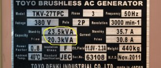
The considered methods for determining the power consumed by the load are also used when measuring the power of DC generators.
Measuring power in a direct current circuit by the direct method is mainly carried out using wattmeters of an electrodynamic system.
where I1 and I2 are the currents flowing through the fixed and moving coils, respectively; f(α)
- a function that takes into account the change in torque depending on the angle of rotation a of the moving coil (due to a change in the mutual induction between the coils).
The counteracting moment is created by the conductive springs of the moving coil
Please note that in accordance with Federal Law N 273-FZ “On Education in the Russian Federation”, organizations engaged in educational activities organize the training and education of students with disabilities, both together with other students and in separate classes or groups.
“The relevance of creating school conciliation/mediation services in educational organizations”
Certificate and discount on training for each participant
Topic: Measurement of active and reactive power in three-phase electrical circuits using the one-wattmeter method.
Goal: Learn to measure experimentally using the one-wattmeter method
The method is used when measuring power in symmetrical three-phase circuits. To measure active power, the voltage winding of the wattmeter is connected to the phase voltage, and the current winding is connected to the wire of any phase. To obtain the active power of the entire three-phase circuit, it is necessary to triple the wattmeter readings: P = ZR.
To measure reactive power, the voltage winding of the wattmeter is switched on to line voltage (dashed line). To obtain the reactive power of the entire three-phase circuit, it is necessary to multiply the wattmeter readings by v 3: Q = V 3 P.
1. Familiarize yourself with the devices necessary for work, write down their basic technical data in Table 1.
2. Determine the terminals of the series and parallel windings of the wattmeter.
3. Connect the devices according to the diagram given above and show it to the teacher for checking.
4. Connect the circuit according to the circuit for measuring active power and measure the active power according to the data of the wattmeter R. Based on the readings, determine P for the entire circuit.
5. Connect the circuit according to the circuit for measuring reactive power (dashed line) and measure the reactive power according to the wattmeter R. Based on the readings, determine Q of the entire circuit.
6. Compare the power value according to the readings of a wattmeter, ammeter, voltmeter.
8.
Record observations and calculations in a table.
1. What is the measurement limit of electrical measuring instruments?
8.
Record observations and calculations in a table.
Expert opinion
It-Technology, Electrical power and electronics specialist
Ask questions to the “Specialist for modernization of energy generation systems”
Three-phase circuit power under unbalanced load briefly. In conclusion, we note that if, when connecting to a star, linear voltages are specified, which is usually the case in practice, then taking into account the fact that the sum of the latter is zero, they can be uniquely specified using two sources of EMF, for example, and. Ask, I'm in touch!