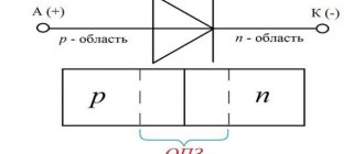
What is a three-phase network?
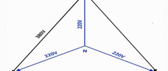
Before putting into operation, any house or apartment is connected to the local power grid. Such a network can be single-phase or three-phase. With a single-phase connection, two wires are supplied to the house, a phase and a zero, between which the voltage is 220 V. A three-phase network is characterized by the presence of four wires: three phases and a zero. Between each phase and zero the voltage is 220 V, and between the phases themselves 380 V (as shown in the image).
To account for electricity in such a network, a three-phase meter is required, which is installed by the local distribution zone. A typical example of such a meter is INCOTEX Mercury 231 AM-01, designed for metering active electricity.
Calculation of power by current and voltage
This calculation occurs based on the actual power; it must be done before you start designing your home (house, apartment).
- This value determines the cables that power the devices that are connected to the electrical network.
- Using the formula, you can calculate the current strength; for this you need to take the exact network voltage and the load of the powered devices. Its size gives us an idea of the cross-sectional area of the veins.
If you know all the electrical appliances that should be powered from the network in the future, then you can easily make calculations for the power supply diagram. The same calculations can be performed for production purposes.
Single-phase 220 volt network
Current formula I (A - amperes):
Where P is the electrical full load (its designation must be indicated in the technical data sheet of this device), W - watt;
U—mains voltage, V (volts).
The table shows the standard loads of electrical appliances and the current they consume (220 V).
| electrical appliance | Power consumption, W | Current strength, A |
| Washing machine | 2000 – 2500 | 9,0 – 11,4 |
| Jacuzzi | 2000 – 2500 | 9,0 – 11,4 |
| Electric floor heating | 800 – 1400 | 3,6 – 6,4 |
| Stationary electric stove | 4500 – 8500 | 20,5 – 38,6 |
| microwave | 900 – 1300 | 4,1 – 5,9 |
| Dishwasher | 2000 — 2500 | 9,0 – 11,4 |
| Freezers, refrigerators | 140 — 300 | 0,6 – 1,4 |
| Electric meat grinder | 1100 — 1200 | 5,0 — 5,5 |
| Electric kettle | 1850 – 2000 | 8,4 – 9,0 |
| Electric coffee maker | 6з0 — 1200 | 3,0 – 5,5 |
| Juicer | 240 — 360 | 1,1 – 1,6 |
| Toaster | 640 — 1100 | 2,9 — 5,0 |
| Mixer | 250 — 400 | 1,1 – 1,8 |
| Hairdryer | 400 — 1600 | 1,8 – 7,3 |
| Iron | 900 — 1700 | 4,1 – 7,7 |
| Vacuum cleaner | 680 — 1400 | 3,1 – 6,4 |
| Fan | 250 — 400 | 1,0 – 1,8 |
| TV | 125 — 180 | 0,6 – 0,8 |
| Radio equipment | 70 — 100 | 0,3 – 0,5 |
| Lighting devices | 20 — 100 | 0,1 – 0,4 |
In the figure you can see a diagram of the power supply device at home with a single-phase connection to a 220 volt network.
Device diagram for single-phase voltage
As shown in the figure, all consumers must be connected to the appropriate machines and meter, then to a general machine that will withstand the total load of the house. The cable that will carry the current must withstand the load of all connected household appliances.
The table below shows hidden wiring for a single-phase housing connection to select a cable at a voltage of 220 volts.
| Wire core cross-section, mm 2 | Conductor core diameter, mm | Copper conductors | Aluminum conductors | ||
| Current, A | Power, W | Current, A | power, kWt | ||
| 0,50 | 0,80 | 6 | 1300 | ||
| 0,75 | 0,98 | 10 | 2200 | ||
| 1,00 | 1,13 | 14 | 3100 | ||
| 1,50 | 1,38 | 15 | 3300 | 10 | 2200 |
| 2,00 | 1,60 | 19 | 4200 | 14 | 3100 |
| 2,50 | 1,78 | 21 | 4600 | 16 | 3500 |
| 4,00 | 2,26 | 27 | 5900 | 21 | 4600 |
| 6,00 | 2,76 | 34 | 7500 | 26 | 5700 |
| 10,00 | 3,57 | 50 | 11000 | 38 | 8400 |
| 16,00 | 4,51 | 80 | 17600 | 55 | 12100 |
| 25,00 | 5,64 | 100 | 22000 | 65 | 14300 |
As shown in the table, the cross-section of the cores also depends on the material from which it is made.
How are three phases different from one?
In both types of power there is a working neutral conductor (ZERO). I talked in detail about protective grounding here; it is a broad topic. In relation to zero in all three phases - the voltage is 220 Volts. But in relation to these three phases to each other, they have 380 Volts.
Voltages in a three-phase system
This happens because the voltages (with active load, and current) on the three phase wires differ by a third of the cycle, i.e. at 120°.
You can read more in the electrical engineering textbook - about voltage and current in a three-phase network, and also see vector diagrams.
It turns out that if we have three-phase voltage, then we have three phase voltages of 220 V each. And single-phase consumers (and there are almost 100% of them in our homes) can be connected to any phase and zero. You just need to do this in such a way that the consumption in each phase is approximately the same, otherwise phase imbalance is possible.
Power supply to consumers from a three-phase power supply system
In very rare cases, electrical energy consumers are supplied directly from generators. Such systems are used only in cases of emergency power outage (diesel generators or gasoline generators) or in places where extending power lines is not economically feasible.
Therefore, for the most part, consumers of electrical energy receive power from the secondary windings of transformers, which, like generators, also have an almost symmetrical EMF system. Therefore, as a rule, it is rarely taken into account how the EMF is created at the load - by transformers or generators.
Not only three-phase consumers, but also single-phase ones, and also, for the most part, DC consumers (through controlled or uncontrolled rectifiers) receive power from three-phase electricity sources.
Also, a three-phase receiver of electrical energy can be considered as a device that consists of three two-terminal networks having the same parameters, which are connected to each wire of a circuit between which there are voltages, shifted in phase relative to each other by an angle equal to 2π/3 or 1200. Each two-terminal network is called AC mains phase. The most common three-phase consumers are asynchronous electric motors, electromagnets, and electric furnaces.
A single-phase electricity receiver can be considered as an ordinary two-terminal network, which is designed to be connected to two network wires and has one voltage, unlike a three-phase one. Single-phase electrical receivers include lighting lamps, low-power asynchronous electric motors, household electrical appliances and other devices.
Power distribution system
Initially, the voltage is always three-phase. By “initially” I mean a generator at a power plant (thermal, gas, nuclear), from which a voltage of many thousands of volts is supplied to step-down transformers, which form several voltage stages. The last transformer lowers the voltage to a level of 0.4 kV and supplies it to end consumers - you and me, apartment buildings and the private residential sector.
Large enterprises with power consumption of more than 100 kW usually have their own 10/0.4 kV substations.
Visually:
Three-phase power supply – stages from generator to consumer
The figure shows in a simplified way how from generator G a voltage (everywhere we are talking about three-phase) 110 kV (can be 220 kV, 330 kV or another) is supplied to the first transformer substation TP1, which lowers the voltage for the first time to 10 kV. One such transformer substation is installed to power a city or region and can have a capacity of the order of a few to hundreds of megawatts (MW).
Next, the voltage is supplied to the second stage transformer TP2, at the output of which the end-user voltage is 0.4 kV (380V). The power of transformers TP2 is from hundreds to thousands of kW. From TP2, voltage is supplied to us - to several apartment buildings, to the private sector, etc.
Such voltage level conversion stages are necessary in order to reduce losses during the transportation of electricity. Read more about losses in cable lines in my other article.
The circuit is simplified, there may be several steps, the voltage and power may be different, but the essence does not change. There is only one final voltage of consumers - 380 V.
Three-phase power: advantages
The presence of three phases brings a lot of advantages to the owner of a private house or cottage. Here are some of them:
- Increased capacity
Every year the number of household electrical appliances in each home increases, which means their total power and the load they transfer to the electrical grid increase. Today in Russia, local Oblenergos offer the opportunity to draw up a contract for the consumption of 5 kW for single-phase networks and 15 kW for three-phase networks.
Let's assume you have one phase and the total power of all electrical appliances in your house is 4 kW. But time passed, and you decided to buy yourself a 3 kW welding machine. By the way, you can read about which welding machine to buy here. In this case, the total power will be 7 kW, and you will not be able to use all devices at the same time. And if in the future you plan to install pumping equipment or an electric heating system, then you should think about connecting a three-phase network.
- Even load distribution
Thanks to the operation of three phases simultaneously, it is possible to evenly distribute the load between them to avoid distortion. For example, if you regularly weld in the garage, it is best to do it on a different phase to which the TV, computer equipment or light bulbs in the house are connected. You can calculate the load for each household appliance and distribute them proportionally across phases.
There are also cases when, due to increased load (not through your fault), the voltage drops to 170 V or even lower on certain phases. This often happens if the house is located at a great distance from the transformer substation, and there are dozens of other consumers in front of it. In this case, the equipment can be temporarily switched to a less loaded phase, and when the imbalance “goes away”, everything can be returned to its place.
- Operation of three-phase equipment
Although most household appliances operate on 220 V, there is still equipment for three-phase networks of 380 V. The following types of such equipment can be distinguished:
- Pumping stations. Some deep and surface pumping stations require 380 V.
- Transformer welding machines.
- Heating boilers. Most electric heating boilers have a rated power of 7 - 9 kW - a single-phase network simply would not cope with it. For example, for a single-circuit boiler EVAN Warmos-IV-9.45 with a power of 9.45 kW, three phases are required.
- Possibility of installing automatic circuit breakers and RCDs with lower nominal values
Due to the fact that each phase wire in a three-phase network will have a lower load than on one phase in the case of a single-phase input, it is possible to install circuit breakers and RCDs with lower current loads. For example, if devices with a total power of 3 kW are placed on each phase, then each phase will require an automatic machine capable of withstanding such a load:
3000/220 = 13.6 A (phase load)
The closest machine is rated at 16 A. For single-phase power supply with a maximum possible power of 5 kW, you will need a more powerful machine. The same rule applies to residual current devices. We have already written about how to choose an RCD based on power, so we will not dwell on this.
Disadvantages of three-phase power
Three-phase power also has several unpleasant aspects that should be considered before connecting:
- Connection and equipment costs
It will be interesting➡ How to make a metal detector with your own hands
If you already have a single-phase input into your house, then reconnecting to a three-phase one will require additional expenses. Such expenses include:
- Registration of the contract. According to current legislation, drawing up an agreement for the installation of a three-phase input and a meter costs 550 rubles.
- Purchase of a meter and wires. The average cost of a three-phase meter included in the state register is 1,500 rubles. Also, for input you will need approximately 20 m of insulated SIP cable with a cross-section of 16 mm2, costing 1,200 rubles. It is also worth considering the need to organize wiring inside the house for a three-phase house. This indicator is difficult to calculate, since all houses are different in size.
- Additional machines. Each phase will require its own machine. You will also need to install a voltage monitoring relay so that you can always “monitor” the voltage in each phase and, in case of distortions, switch between phases.
In order for electricians to connect you to a three-phase network, you will have to stand in line and wait a couple of weeks. If you don’t want to wait, you will have to pay separately for urgency. As a result, connecting three-phase power will cost its owner a tidy sum.
- Increased dimensions of the panel room
To connect three-phase power it is necessary to install a large switchboard. This is due to the presence of additional protective and distribution equipment. Typically, such a power cabinet or switchboard is installed outdoors so that it does not take up much space in the house.
It is worth noting that energy sales have certain requirements for distribution boards. For example, protection of the switchboard from dust and dirt should be at least IP31, and in wet rooms IP54. For some owners of summer cottages or private houses, finding a suitable place for a cabinet or installing such a structure can be a real challenge.
- Re-wiring in the house
If initially the house had one phase, then connecting two more will require the owner to completely redesign the wiring. So initially all sockets and light bulbs were “planted” on one phase. With a three-phase connection, these sockets will need to be moved, and this means considerable repairs in the house, since you will have to trench the walls for the wiring. Naturally, this work requires additional time and money.
Peculiarities
To reduce the likelihood of phase overload, the load is distributed evenly across phases. Failure to comply with this condition, as well as burnout of the “zero” conductor or its poor contact, will lead to a difference in voltage on the phase conductors, up or down.
Thus, converted single-phase power (220 V) will lead to malfunction of electrical consumers connected to it. This will happen due to the fact that some devices will receive an increased voltage (240-270 V), while others will receive a reduced voltage (160-200 V).
Important! If the load is unevenly distributed across phases, on meters that are not sensitive to distortions, there will be an increased consumption of electricity.
Calculation of Power by Current and Voltage
To protect yourself when working with household electrical appliances, you must first correctly calculate the cross-section of the cable and wiring. Because if the cable is chosen incorrectly, it can lead to a short circuit, which can lead to a fire in the building, the consequences can be catastrophic.
This rule also applies to the choice of cable for electric motors.
The emergence of the three-phase voltage concept
Dolivo-Dobrovolsky is considered the father of three-phase voltage in Russia and Nikola Tesla in the rest of the world. Events relating to the era of the emergence of the subject of the dispute took place in the 80s of the 19th century. Nikola Tesla demonstrated the first two-phase motor while working for a company where he set up electrical installations for various purposes. Interest in the phenomenon of electrification of domestic cat fur led the scientist to great discoveries. While walking in the park with a friend, Nikola Tesla realized that he would be able to put into practice Arago’s theory of a rotating magnetic field, and he would need:
- Two phases.
- The shift between them is at an angle of 90 degrees.
To show the great significance of the discovery, we note that Yablochkov’s transformer did not gain mass popularity at the indicated time, and Faraday’s experiments on magnetic induction were safely forgotten, only the formula of the law was written down. The world didn't want to know about:
- alternating current;
- phase;
- reactive power.
Generators (alternators) and dynamos rectified the voltage using a mechanical commutator. The entire electricity industry, which was meager at that time, languished in a similar way. Edison was just beginning to invent; no one really knew about the incandescent light bulb yet. By the way, in the Russian Federation they believe that the device was invented by Lodygin.
Tesla's idea looked revolutionary; it remained unknown how to obtain two phases with a given interphase shift. The young scientist had little interest in the question. He read about the reversibility of electric machines and radiated confidence that he could easily build a generator by arranging the windings accordingly. There were no difficulties with the drive. At the beginning of the 80s, steam was actively used, the demonstration model was supposed to be powered by a dynamo.
3 phase image
Tesla did not set out to obtain a certain frequency. No research was carried out; it was simply necessary to make the rotor rotate. The idea was realized through slip rings. At that time, brushed DC motors were equipped with similar contacts; Tesla’s conclusion is not surprising. It is more interesting to explain the choice of the number of phases.
Three-phase circuits. How is voltage applied to them?
In a three-phase circuit, the voltage can be phase or linear. The vector diagram looks like this:
The graph contains three voltage (phase) vectors – Uа, Ub and Uс. The angle between them is 120°. This is observed between windings in the simplest electrical equipment. In order for the sign of the vector Ub to change to the opposite, it must be reflected in such a way that the vector beginning and end are swapped, while the original angle of inclination is preserved. After setting the vector beginning Ub to the end Ua, the resulting distance will be considered as the linear voltage vector (Ul).
"Δ" scheme
By connecting the end of each phase of the power receiver to the beginning of the next, you can obtain a three-phase current with phases connected in series. The resulting circuit configuration is called a "triangle". In this form, it can only operate as a three-wire one.
With the help of vector constructions, understandable even for dummies, phase and linear voltages and currents are illustrated. Each phase of the electrical receiver is connected to a linear voltage between two conductors. Line and phase voltages are identical at the power receiver.
Scheme “Δ” and construction of vectors
Interphase currents for the “triangle” are I(A), I(B), I(C). Phase – I(AB), IBC), I(CA).
Linear currents are found from vector constructions:
- I(A) = I(AB) – I(CA);I(B) = I(BC) – I(AB);I(C) = I(CA) – I(BC).
The summing current quantity in a symmetrical system corresponds to zero. RMS values of phase currents:
I(AB) = I(BC) = I(CA) = U/Z.
Since the phase shift between U and I is 30°, the line current in this configuration will be equal to:
I(A) = I(AB) – I(CA) = 2 x I(AB) x cos 30° = 2 x Iph x √3/2 = √3 x Iph.
Important! The effective value of the line current is √3 times the effective value of the phase current.
Where is the voltage used at 220V, and where at 380V?
In most residential buildings (apartments, houses, cottages and country houses), single-phase electrical networks are installed and used, in which the voltage is standard 220V. This is justified by the fact that the level of consumption in an ordinary house or apartment does not, as a rule, exceed 10 kW.
A three-phase electrical network is installed at facilities where the planned level of power consumption exceeds 10 kW, and electrical installations are installed and used that require a three-phase voltage supply to ensure correct operation. For example, if you use only one phase using a capacitor to start a three-phase motor, this will significantly reduce the efficiency of the electrical installation and at the same time increase the consumption of electrical energy.
On the other hand, if the level of maximum power consumption in a private household does not exceed 9 kW, it is permissible to use a two-core copper cable with a cross-section of 6 mm at the input and install a 40A machine.
In the case where the maximum load is supposed to be 15 kW, for a wire of one phase the value of the passing current will be 70A. Therefore, it will be necessary to install a copper wire with a 10 mm cross-section and a power circuit breaker. However, the cost of such a network is much more expensive. Therefore, a way out of the situation may be to install a conventional three-phase network and distribute the effective load equally between the phases, that is, 5 kW each. Today, such power supply solutions are used by most shops, enterprises and offices.
Selecting the rating of the circuit breaker
Applying the formula I = P/209, we find that with a load with a power of 1 kW, the current in a single-phase network will be 4.78 A. The voltage in our networks is not always exactly 220 V, so it would not be a big mistake to calculate the current strength with a small margin like 5 A for every kilowatt of load. It is immediately clear that it is not recommended to connect an iron with a power of 1.5 kW to an extension cord marked “5 A”, since the current will be one and a half times higher than the rated value. You can also immediately “graduate” the standard ratings of the machines and determine what load they are designed for:
- 6 A – 1.2 kW;
- 8 A – 1.6 kW;
- 10 A – 2 kW;
- 16 A – 3.2 kW;
- 20 A – 4 kW;
- 25 A – 5 kW;
- 32 A – 6.4 kW;
- 40 A – 8 kW;
- 50 A – 10 kW;
- 63 A – 12.6 kW;
- 80 A – 16 kW;
- 100 A – 20 kW.
Using the “5 amperes per kilowatt” technique, you can estimate the current strength that appears in the network when connecting household devices. You are interested in peak loads on the network, so for the calculation you should use the maximum power consumption, not the average. This information is contained in the product documentation. It is hardly worth calculating this indicator yourself by summing up the rated powers of the compressors, electric motors and heating elements included in the device, since there is also such an indicator as the efficiency factor, which will have to be assessed speculatively with the risk of making a big mistake.
When designing electrical wiring in an apartment or country house, the composition and passport data of the electrical equipment that will be connected are not always known for certain, but you can use the approximate data of electrical appliances common in our everyday life:
- electric sauna (12 kW) - 60 A;
- electric stove (10 kW) - 50 A;
- hob (8 kW) - 40 A;
- instantaneous electric water heater (6 kW) - 30 A;
- dishwasher (2.5 kW) - 12.5 A;
- washing machine (2.5 kW) - 12.5 A;
- Jacuzzi (2.5 kW) - 12.5 A;
- air conditioner (2.4 kW) - 12 A;
- Microwave oven (2.2 kW) - 11 A;
- storage electric water heater (2 kW) - 10 A;
- electric kettle (1.8 kW) - 9 A;
- iron (1.6 kW) - 8 A;
- solarium (1.5 kW) - 7.5 A;
- vacuum cleaner (1.4 kW) - 7 A;
- meat grinder (1.1 kW) - 5.5 A;
- toaster (1 kW) - 5 A;
- coffee maker (1 kW) - 5 A;
- hair dryer (1 kW) - 5 A;
- desktop computer (0.5 kW) - 2.5 A;
- refrigerator (0.4 kW) - 2 A.
The power consumption of lighting devices and consumer electronics is small; in general, the total power of lighting devices can be estimated at 1.5 kW and a 10 A circuit breaker is sufficient for a lighting group. Consumer electronics are connected to the same outlets as irons; it is not practical to reserve additional power for them.
If you sum up all these currents, the figure turns out to be impressive. In practice, the possibility of connecting the load is limited by the amount of allocated electrical power; for apartments with an electric stove in modern houses it is 10 -12 kW and at the apartment input there is a machine with a nominal value of 50 A. And these 12 kW must be distributed, taking into account the fact that the most powerful consumers concentrated in the kitchen and bathroom. Wiring will cause less cause for concern if it is divided into a sufficient number of groups, each with its own machine.
For the electric stove (hob), a separate input with a 40 A automatic circuit breaker is made and a power outlet with a rated current of 40 A is installed; nothing else needs to be connected there. A separate group is made for the washing machine and other bathroom equipment, with a machine of the appropriate rating. This group is usually protected by an RCD with a rated current 15% greater than the rating of the circuit breaker. Separate groups are allocated for lighting and for wall sockets in each room.
You will have to spend some time calculating powers and currents, but you can be sure that the work will not be in vain. Well-designed and high-quality electrical wiring is the key to the comfort and safety of your home.
According to what schemes do consumers connect to three-phase electrical networks?
To connect electric motors, heaters and other three-phase power, a star or delta circuit is used. Most installations are equipped with jumpers, which, depending on the position of the windings, form the above circuits.
Star connection
The scheme provides for connecting the ends of the windings of the generating device at one point and connecting the same load windings to the beginning. In electric motors, it turns out that a linear voltage of 380V, provided the windings are connected in a star circuit, is applied to two windings for each phase pair.
It will be interesting➡ What is a contactor, its features and connection diagrams
Delta connection
This circuit provides for the application of line voltage to each winding. These elements, as a rule, are designed for just such connections.
These connection methods have both advantages and disadvantages.
Three-phase circuit diagrams
The windings of a generator or transformer in three-phase circuits can be connected to each other according to two schemes:
- star;
- triangle.
Connections are made on the terminal block (boron) of the unit or transformer, where the ends of the windings are brought out.
Jumper connection of windings
Connecting the load to the generator (transformer) can be done according to the following schemes:
- star-star connection using a neutral conductor;
- star-star connection without using a neutral wire;
- star-delta connection;
- "triangle-triangle" scheme;
- delta-star connection.
Attention! This variety of circuits is due to the fact that the generator's own windings and the load's own windings can be connected in different ways. With different types of coupling, different correspondences between phase and linear values are obtained.
The connection can be made at the factory when assembling the generator; the second ends of the windings are already brought out to the point where the power cable is connected. Information about the winding connection diagram is applied to a plate attached to the stator of the machine.
On electric motors, transformers or other consumers, the necessary manipulations are also performed to switch winding terminals. In the picture below, the ends of the windings connected by a jumper are marked with a red marker. Blue marker - power phases.
Connections on boron motor
Star connection
The letter designation of the beginning of the windings is “A”, “B”, “C”, the ends are “X”, “Y”, “Z”. The zero point is marked “O”. Each winding has two ends. When connecting “star”, all three winding terminals of the same name (beginning) are connected to each other at one point “O”. The load is connected to the free ends.
Star winding connection diagram
Delta connection
When making this connection, jumpers are placed on the board, turning on the windings in the following sequence:
- the end of “A” - with the beginning of “B”;
- end “B” – with beginning “C”;
- the end of "C" - with the beginning of "A".
The graphic image of the coils becomes similar to a triangle, hence the name.
When they want to use a plug-in asynchronous motor with maximum efficiency, its windings are connected in a triangle. In this case, the phase voltages coincide (Ul = Uph), the line current will be calculated by the formula:
Il = √3*Iph.
When connecting a motor as a load, it is necessary to take into account a number of nuances:
- an increase in power by 1.5 times is achieved;
- the value of the starting current increases 7 times compared to the operating current due to difficult starting;
- a sharp increase in the load on the electric machine shaft will cause a sharp increase in current.
Because of all this, there is a risk of the machine overheating, which does not happen when the load windings are connected in a star configuration. There, the engine is not prone to overheating, and it starts smoothly.
Switching on the windings according to the "triangle" pattern
With two types of winding connection, two types of currents are distinguished and defined: linear and phase. It's easy to remember the differences:
- the current flowing through the conductor that connects the source to the receiver is called linear;
- The current moving through the windings of the source or load is called phase.
It is worth paying attention to the power formulas for various schemes for connecting the source to the load.
The current power in a star circuit is determined by the formula:
P = 3*Uф*Iф*cosϕ = √3*Uл*Iл*cosϕ,
Where:
- Uph – phase voltage;
- Uл – linear voltage;
- Iph – phase current;
- Il – linear current;
- cosϕ – phase shift.
The current power in a delta circuit is calculated by the formula:
P = 3* Uф* Iф*cosϕ = √3*Uл*Iл*cosϕ.
For your information. It is necessary to pay attention to linear and phase currents when the generator (source) is loaded asymmetrically when the load is connected.
Connections in a three-phase circuit
Options for connecting a 3-phase motor to the electrical network
Asynchronous three-phase motors are common in production and everyday life. The peculiarity is that they can be connected to both three-phase and single-phase networks. In the case of single-phase motors, this is impossible: they only operate when powered by 220V. What are the ways to connect a 380 Volt motor? Let's look at how to connect stator windings depending on the number of phases in the power supply using illustrations and a training video.
Using 3 phases
If you live in an apartment building, then 3 phases are already connected to it, which, in order to optimally distribute the loads, are separated into individual apartments. On each floor there are distribution boards, from where you can bring the missing two phases into the apartment. But this will require permission.
If you wish, you can obtain permission from the energy supply company or coordinate with Energonadzor the installation of three-phase power in your apartment. In this case, you will need to install a three-phase electricity meter.
Using an electric motor
You probably know that the rotor of a conventional three-phase motor, after starting, continues to rotate after one phase is disconnected. It turns out that there is an EMF between the terminal of the disconnected winding and the activated terminals.
The phase shift between the stator windings depends only on their location. In a three-phase motor, these coils are located at an angle of 120º, which means they provide the same phase shift angle. This circumstance suggests that an asynchronous three-phase motor can be used to obtain 380 volts from a conventional single-phase network. A simple diagram for connecting an electric motor is shown in Figure 3. The capacitor in the diagram is needed only to start the engine. Once launched, you can disable it. We take the capacitor type MBGO, MBGP, MBGT or K42-4, the operating voltage of which must be at least 600 V. You can use the capacitor K42-19, with an operating voltage of at least 250 V.
Example of calculating total power for an electric motor
The power of electric motors can be useful or mechanical on the shaft and electrical. They differ by the coefficient of performance (efficiency), this information is usually indicated on the nameplate of the electric motor.
From here we take the data to calculate the connection in a triangle to Ulinear 380 Volts:
Then you can find the active electrical power using the formula:
P=Pon the shaft/n=160000/0.94=170213 W
Now we can find S:
It is this that needs to be found and taken into account when selecting a cable or transformer for an electric motor. This completes the calculations.
Three-phase input and increasing power in the apartment
To increase the level of comfort in an apartment, you first need to reach the required amount of allocated power per apartment. You can understand this value by calculating the power based on the selected equipment. Almost always, an apartment is equipped with a single-phase input, but powerful modern equipment requires a three-phase input. Finally, it is necessary to obtain the missing power, put the new electrical installation of the apartment into operation and apply voltage. All these issues can be solved, but require a serious systematic approach. The first thing you need to do is contact the operating organization (MC, HOA, DEZ), get a certificate about the amount of power allocated to the apartment and find out the possibility of increasing the power. Any options are possible, but almost always the power is there, but you have to pay for it. In new houses, a reserve for sale is specially laid down during construction; in old houses, this is ensured by a safety margin from Soviet times. The cost of increasing power will be determined as a result of negotiations with the operating organization, while it must be taken into account that the consumer does not have any legal rights to receive additional power. You should not quarrel with the operating organization, as it may simply refuse you, citing disagreement with using its network or charging an exorbitantly high price. You must understand that the electrical network of your apartment is connected to the electrical network of another balance holder (MC, HOA, DEZ), which has every right to refuse you additional use of its network and not give you a new connection point to its network. Unfortunately, it is almost impossible to connect an apartment directly to the network of the electric grid company (to a transformer substation or input device), since this is extremely expensive and difficult due to the small amount of connected power. Having received the consent of the operating organization, it is necessary to conclude a purchase and sale agreement for electric power and obtain permission to connect the power to the networks of the electric grid company. A three-phase input must be specified in the power connection permit if you expect to connect three-phase equipment. According to the new laws, the cost of obtaining power under a power purchase and sale agreement is negligible for household consumers up to 15 kilowatts. Power over 15 kilowatts is paid at high tariffs for legal entities. It is advisable to agree with the operating organization so that the point of connection of the new power is as close as possible to the apartment (in the riser on the landing). This will save money when laying a new cable line. In the worst case, you will have to run a new cable line to the ASU of the building, which may be located in the basement of another entrance. If you have permission to connect and have completed work on supplying additional power, the energy sales company will enter into a new power supply contract with you without additional conditions. A power supply project is not required in this case. The only condition of the energy sales company is the availability of the required electricity meter. If you have special knowledge, it is possible to independently complete the paper part of this set of works, but in any case, for the apartment owner, the results of the negotiations will be much worse in monetary terms than for intermediary organizations. It is more profitable to entrust the entire complex of work to one authorized organization and receive a discount for the complex of work.
Voltage between two phases
In this short article, without going into the history of AC networks, we will understand the relationships between phase and line voltages. We will answer questions about what phase voltage is and what line voltage is, how they relate to each other and why these relationships are the way they are.
It's no secret that today electricity from generating power plants is supplied to consumers via high-voltage power lines with a frequency of 50 Hz. At transformer substations, high sinusoidal voltage is reduced and distributed to consumers at the level of 220 or 380 volts. Somewhere the network is single-phase, somewhere three-phase, but let's figure it out.
Effective value and amplitude value of voltage
First of all, we note that when they say 220 or 380 volts, they mean the effective voltage values, expressed in mathematical language - root mean square voltage values. What does it mean?
note
This means that in fact, the amplitude Um (maximum) of the sinusoidal voltage, phase Umph or linear Uml, is always greater than this effective value. For a sinusoidal voltage, its amplitude is greater than the effective value by the root of 2 times, that is, 1.414 times.
So for a phase voltage of 220 volts, the amplitude is equal to 310 volts, and for a linear voltage of 380 volts, the amplitude will be equal to 537 volts. And if we take into account that the voltage in the network is never stable, then these values can be either lower or higher. This circumstance should always be taken into account, for example, when choosing capacitors for a three-phase asynchronous electric motor.
Phase mains voltage
The windings of the generator are connected in a star configuration, and the ends X, Y and Z are connected at one point (at the center of the star), which is called the neutral or zero point of the generator. This is a four-wire, three-phase circuit. Linear wires L1, L2 and L3 are connected to the terminals of windings A, B and C, and neutral wire N is connected to the zero point.
The voltages between terminal A and the zero point, B and the zero point, C and the zero point are called phase voltages, they are designated Ua, Ub and Uc, but since the network is symmetrical, you can simply write Uph - phase voltage.
In three-phase AC networks in most countries, the standard phase voltage is approximately 220 volts - the voltage between the phase wire and the neutral point, which is usually grounded and its potential is taken to be zero, which is why it is also called the neutral point.
Three-phase line voltage
It will be interesting➡ How does thermal resistance work?
The voltages between terminal A and terminal B, between terminal B and terminal C, between terminal C and terminal A are called linear voltages, that is, these are the voltages between the linear conductors of a three-phase network. They are designated Uab, Ubc, Uca, or you can simply write Ul.
Standard line voltage in most countries is approximately 380 volts.
It is easy to notice in this case that 380 is 1.727 times greater than 220, and, neglecting losses, it is clear that this is the square root of 3, that is, 1.732.
Important
Of course, the voltage in the network fluctuates all the time in one direction or another depending on the current load on the network, but the relationship between linear and phase voltages is exactly that.
Where does the root of 3 come from?
In electrical engineering, the vector method of depicting voltages and currents that vary sinusoidally over time is often used. The method is based on the position that when a certain vector U rotates around the origin with a constant angular velocity ω, its projection onto the Y axis is proportional to the sine ωt, that is, the sine of the angle ω between the vector U and the X axis, which is determined at each time.
The graph of the projection magnitude versus time is a sinusoid. And if the voltage amplitude is the length of the vector U, then the projection that changes over time is the current voltage value, and the sinusoid U(ωt) reflects the voltage dynamics.
So, if we now draw a vector diagram of three-phase voltages, it turns out that between the vectors of the three phases there are identical angles of 120°, and then if the lengths of the vectors are the effective values of the phase voltages Uph, then in order to find the linear voltages Ul, it is necessary to calculate the DIFFERENCE of any pair vectors of two phase voltages. For example Ua – Ub.
Having carried out the construction using the parallelogram method, we see that the vector Ul = Ua + (-Ub), and as a result Ul = 1.732Uph. Hence it turns out that if standard phase voltages are equal to 220 volts, then the corresponding linear ones will be equal to 380 volts.
Electric machine converters
Electrical machine converters serve as sources of secondary and emergency ESSs and produce a single-phase voltage of 115 V or three-phase 36 V, consuming direct current with a voltage of 27 V.
Electric machine converters have the shape of a cylinder in which a DC motor and an AC generator are placed on a common shaft with common bearings and a ventilation system.
On top of the cylinder there is a box in which there is an automatic control system (AVR) for voltage and frequency, a DC power contactor. On the box there are terminals for connecting DC wires and a connector for outputting alternating current and converter switching circuits. Electric machine converters, while relatively cheap, have significant disadvantages, these are: low efficiency, less than 50%; high noise during operation, short service life between repairs.
Fig. 7.1 Block diagram of an electric machine converter. The block diagram shows separately the voltage and frequency regulation channels. The elements are indicated on the diagram: D - motor (armature), G - generator (stator), CO - serial (serial) winding, UOD - motor control winding, UOG – control winding of the generator, UC – frequency amplifier; UN – voltage amplifier, IOC – frequency measuring organ, ION – voltage measuring organ. Frequency regulator channel UOD-UCH-UOCh, voltage regulator channel UOG-UN-ION.
CO is designed to create the main magnetic flux in the motor gap due to network energy = 27 V, thereby unloading the power frequency regulator (reduces the share of magnetic flux from the UOD) and increasing the starting torque of the engine. Let's consider the operation of the frequency regulator channel. The generator frequency is determined by the expression f = Р n/60, where P is the number of pole pairs, n is the generator revolutions per minute. The generator revolutions depend on the engine speed, since they are on the same shaft.
The revolutions of a DC motor are described by the expression n = (U- Iа∙Rа)/s·Ф, where U is the supply voltage, I is the armature current, R is the armature resistance, c is the coefficient connecting all quantities and Ф is the magnetic flux in the gap. In our case Ф = Фso + Fuod. From the expression it is clear that it is possible to stabilize the speed n with changing U and I by changing F. Consequently, the circuit is designed in such a way that, throughout the entire range of changes in U and I, the flow is regulated due to Fuod. If the frequency has dropped, then Fuodum decreases and n increases, and vice versa, if the frequency increases, then FuodIOC increases - analyzes the frequency shift ∆f from 400 Hz and generates a signal proportional to the shift kf. – generates a direct current proportional to kf to power the UOD. Thus, the frequency regulator is powered by the energy of the generator. Let's consider the operation of the voltage regulator channel. The generator voltage is determined by the expression Ug = s1∙nФ – Ip∙Rp where c1 is the coefficient, n is the generator revolutions, F is the magnetic flux in the generator gap, Iр is the current of the working winding, Rp is the resistance of the working winding. It is clear from the expression that when changing IрUг, it is possible to regulate the speed n and magnetic flux F. In our diagram, voltage stabilization by magnetic flux is used.
The ION measures the deviation U from 115 V and converts the deviation into a signal kU proportional to the deviation. The UN produces a direct current proportional to the voltage deviation and powers the UOG. Thus, the voltage channel is also supplied from the generator. As a rule, the UOG is located on the rotor and rotates together with the motor armature. The advantages of three-phase current are obvious only to electrician specialists.
What three-phase current is is very vague for the average person. Let's dispel the uncertainty. Most people, with the exception of electrical specialists, have a very vague idea of what the so-called “three-phase” alternating current is, and in terms of what current strength, voltage and electric potential, as well as power, are often confused Let's try to give initial concepts about this in simple language. To do this, let's turn to analogies. Let's start with the simplest one - the flow of direct current in conductors.
It can be compared to the flow of water in nature. Water, as you know, always flows from a higher point on the surface to a lower one. Always chooses the most economical (shortest) path. The analogy with the flow of current is complete. Moreover, the amount of water flowing per unit time through a certain section of the flow will be similar to the current strength in the electrical circuit.
The height of any point of the river bed relative to the zero point - sea level - will correspond to the electrical potential of any point in the chain. And the difference in height of any two points of the river will correspond to the voltage between two points of the circuit. Using this analogy, you can easily imagine in your mind the laws of the flow of direct electric current in the circuit. The higher the voltage - the height difference, the greater the flow speed, and, consequently, the amount of water flowing along the river per unit time.
A water flow, just like an electric current, experiences the resistance of the riverbed during its movement - along a rocky riverbed, water will flow violently, changing direction, heating up a little (stormy streams, even in severe frosts, do not freeze due to heating from the resistance of the riverbed). In a smooth channel or pipe, water will flow quickly and, as a result, in a unit of time the channel will pass much more water than a winding and rocky channel. Resistance to water flow is completely analogous to electrical resistance in a circuit. Now imagine a closed bottle with some water in it.
If we begin to rotate this bottle around a transverse axis, then the water in it will flow alternately from the neck to the bottom and vice versa. This idea is an analogy to alternating current. It would seem that the same water flows back and forth, so what? However, this alternating flow of water is capable of doing work. Yes, ever since humanity learned that moving a magnet near a conductor causes an electric current in the conductor. It is the movement of the magnet that causes the current, if the magnet is placed next to the wire and does not move - This will not cause any current in the conductor.
Next, we want to receive (generate) current in the conductor in order to use it in the future for some purpose. To do this, we will make a coil of copper wire and start moving a magnet near it. The magnet can be moved near the coil as you like - move it in a straight line back and forth, but in order not to move the magnet with your hands, creating such a mechanism is technically more difficult than just starting to rotate it near the coil , similar to spinning the water bottle from the previous example. It was in this way - for technical reasons - that we obtained sinusoidal alternating current, which is now used everywhere.
A sine wave is a description of rotation unfolded in time. Later it turned out that the laws of the flow of alternating current in a circuit differ from the flow of direct current. For example, for the flow of direct current, the resistance of the coil is simply equal to the ohmic resistance of the wires. And for alternating current, the resistance of the wire coil increases significantly due to the appearance of the so-called inductive reactance. Direct current does not pass through a charged capacitor; for it, the capacitor is an open circuit. And alternating current is able to flow freely through the capacitor with some resistance.
It was further discovered that alternating current can be converted using transformers into alternating current of other voltages or currents. Direct current does not lend itself to such transformation, and if we turn on any transformer into a direct current network (which is absolutely impossible to do), then it will inevitably burn out, since the direct current will only be resisted by the ohmic resistance of the wire, which is made as small as possible, and through the primary winding a large current will flow in short circuit mode. Note also that electric motors can be designed to operate on both direct current and alternating current. But the difference between them is this: DC electric motors are more difficult to manufacture, but they allow you to smoothly change the rotation speed with a conventional rheostat that regulates the current strength.
And AC electric motors are much simpler and cheaper to manufacture, but they rotate at only one speed, determined by the design. Therefore, both are widely used in practice. Depending on the purpose. For control and regulation purposes, DC motors are used, and AC motors are used as power plants. Further, the design idea of the inventor of the generator moved approximately in this direction - if it is most convenient to use the rotation of a magnet next to a coil to generate current, then why not instead of one coil generator, can’t you place several coils around a rotating magnet (there’s so much space around)? It will immediately look like several generators operating from one rotating magnet. Moreover, the alternating current in the coils will differ in phase - the maximum current in subsequent coils will be somewhat delayed relative to the previous ones.
That is, the current sinusoids, if depicted graphically, will seem to be shifted among themselves. This important property is phase shift, which we will discuss below. Reasoning approximately this way, the American inventor Nikola Tesla first invented alternating current, and then a three-phase current generation system with six wires. He placed three coils around a magnet at equal distances at angles of 120 degrees, if the axis of rotation of the magnet is taken as the center of the angles. (The number of coils (phases) can actually be any, but to obtain all the advantages that a multiphase current generation system provides, a minimum of three is enough).Next, the Russian electrical engineer Mikhail Osipovich Dolivo-Dobrovolsky developed N.’s invention.
Tesla, for the first time, proposed a three- and four-wire system for transmitting three-phase alternating current. He proposed connecting one end of all three generator windings to one point and transmitting electricity through just four wires. (Savings on expensive non-ferrous metals are significant). It turned out that with a symmetrical load of each phase (equal resistance), the current in this common wire is zero. Because when summing (algebraically, taking into account the signs) currents shifted in phase by 120 degrees, they cancel each other out.
This common wire was called neutral. Since the current in it arises only when the loads of the phases are uneven and numerically it is small, much less than the phase currents, it became possible to use a wire of a smaller cross-section as a “zero” wire than for phase wires. For the same reason (phase shift by 120 degrees) three-phase transformers turned out to be significantly less material-intensive, since mutual absorption of magnetic fluxes occurs in the magnetic core of the transformer and it can be made with a smaller cross-section. Today, a three-phase power supply system is carried out by four wires, three of them are called phase and are designated by Latin letters: on the generator - A, B and C , for the consumer – L1, L2 and L3. The neutral wire is designated 0. The voltage between the neutral wire and any of the phase wires is called phase and in consumer networks is 220 volts.
There is also a voltage between the phase wires, and much higher than the phase voltage.
This voltage is called linear and is 380 volts in consumer circuits. Why is it larger than the phase one? Yes, all this is due to a phase shift of 120 degrees. Therefore, if on one wire, for example, at a given moment in time the potential is plus 200 volts, then on the other phase wire at the same moment in time the potential will be minus 180 volts.
Voltage is the potential difference, that is, it will be + 200 – (-180) = +380 V. The question arises, if current does not flow through the neutral wire, then is it possible to remove it altogether. It is possible. And we will get a three-wire power supply system. With the connection of consumers in the so-called “triangle” - between the phase wires. However, it should be noted that with an uneven load on the sides of the “triangle” the generator will be subject to destructive loads, so this system can be used with a huge number of consumers, when the uneven loads are leveled out. Transmission of electricity from large power plants at high phase and line voltages (hundreds of thousands volts) are carried out this way.
Why is such a high voltage used? The answer is simple - to reduce heating losses in the wires. Since the heating of the wires (energy loss) is proportional to the square of the flowing current, it is desirable that the flowing current be minimal. Well, to transmit the required power at a minimum current, you need to increase the voltage.
Power transmission lines (PTLs) are designated this way, for example, PTL - 500 is a power transmission line with a voltage of 500 kilovolts. By the way, losses in power transmission line wires can be further reduced by using high voltage direct current transmission (the capacitive component of losses acting between the wires ceases to operate ), even such experiments have been carried out, but such a system has not yet become widespread, apparently due to greater savings in wires with a three-phase generation system. Savings on the number of wires required for transmitting electricity. Considering the considerable distances (hundreds and thousands of kilometers) and the fact that non-ferrous metals with low electrical resistance are used for wires, the savings are quite significant. Three-phase transformers, with equal power to single-phase ones, have a significantly smaller magnetic core. Which allows you to get significant savings. It is very important that the three-phase electricity transmission system creates, when a consumer is connected to three phases, a kind of rotating electromagnetic field. Again, due to a phase shift.
This property has made it possible to create extremely simple and reliable three-phase electric motors that do not have a commutator, and the rotor, in fact, is a simple “blank” in bearings, to which no wires need to be connected. (In fact, the design of a squirrel-cage rotor has its own characteristics and is not a blank at all.) These are so-called three-phase asynchronous electric motors with a squirrel-cage rotor. Very widespread today as power plants. A remarkable property of such motors is the ability to change the direction of rotation of the rotor to the opposite direction by simply switching any two phase wires. The ability to obtain two operating voltages in three-phase networks.
In other words, change the power of an electric motor or heating installation by simply switching the supply wires. The ability to significantly reduce the flickering and stroboscopic effect of lamps using fluorescent lamps by placing three lamps in the lamp, powered from different phases. Thanks to these advantages, three-phase power supply systems have become widespread in the world. In Currently, the production and distribution of electrical energy is mainly carried out by three-phase current. Connection diagram of a three-phase meter. Three alternating currents of equal frequency and amplitude, shifted relative to each other by 1/3 periods (120°), form a three-phase system. There are two ways to connect electrical windings machines and receivers in a three-phase system: star connection and delta connection. The three phases of the power supply can be connected to three loads with six wires. Such a chain system is called unconnected. Currently, it is not used. When connecting a three-phase system according to a star circuit, the ends of all windings of the source phases are connected to a common point. The same connection is made in the load.
Then all three return wires are combined into one and connected to the common points of the source and load. The sum of the currents of all three phases flows through this wire. But if the same currents flow in all phases, then their sum will be equal to zero, since they are shifted relative to each other by 120°. Therefore, no current will flow in the common wire.
This wire is called neutral, or zero. The remaining wires connecting the generator windings to the receiver are called linear. The load at which the currents in all phases are equal in magnitude and have the same phase shifts with respect to the phase EMF is called symmetrical. When connected in a star with a symmetrical load, there is no neutral wire, since it is not necessary. Such a system is called three-wire. In other cases, a system with a neutral wire is used - four-wire. The voltages between the end and the beginning of the phase windings in a three-phase system are called phase, and the voltages between linear wires are called linear.
Currents flowing in the phase windings of a source or load are called phase currents, and in linear wires - linear. Between phase and linear quantities when connected in a star, there is the following connection (with a symmetrical load): Relationship between phase and linear quantities. When connected in a triangle, the phase windings of the source are connected in series so that the beginning of one winding is connected to the end of the next. Common points of each pair of phase The source windings and the common points of each pair of receiver branches are connected by wires, which are called linear. It is easy to verify that a delta connection in a three-phase system is also obtained from a three-phase unconnected circuit by combining wires drawn side by side with each other. With a symmetrical load of a system connected in a delta, the linear currents are 3 times greater than the phase ones, and the phase voltages are equal to the linear ones, i.e.
f. Phase and line voltages. Share a useful article: Home> Theory> Three-phase current Most alternating current generators, as well as lines that transmit electricity, use three-phase systems. Current transmission is carried out along three lines (or four) instead of two. Three-phase current is an alternating electric current system where the values of currents and voltages change according to a sinusoidal law. The frequency of sinusoidal current oscillations in Russia and Europe is 50 Hz. Three-phase power lines
Phase and line voltage
The voltage between phase and zero is called phase. On one phase the voltage is always 220 V, and on zero, respectively, 0. Since the difference between them is 220 V, this means the phase voltage will always be 220 V (in a household network there are surges and dips, so the voltage may vary slightly).
But if everything is extremely clear with phase voltage, then with linear voltage everything is not so simple. Line voltage is the voltage between two phases. We know that it is 380V, but where does it come from?
It's all about the operation of the generator, which generates electricity and is installed at the substation. Pay attention to the illustration below. The windings (phases A, B and C) of the generator are located at an angle of 120° relative to each other. The internal inductor or magnet (indicated by the letters C and Y) rotates and creates an electromagnetic field. But since the phases are located at an angle of 120° relative to each other, the rotation of the inductor with respect to each phase is shifted by 1/3 of the cycle. As a result, when a magnet passes near one phase, it excites the winding to a maximum of 220 V, and at the same time the other phase is excited only at -160. In this case, the linear voltage will be Ul = 220 - (-160) = 380 V.
Also, for a four-wire wiring system when connecting a three-phase generator with a star, there is the following formula: Ul = square root of 3 * Uph, where Uph is the phase voltage, which is equal to 220 V. As a result, we get Ul = 1.73 * 220 = 380 V.
No matter how you decide to carry out the calculations, you will arrive at 380 V.
Three-phase AC system
Three-phase system networks are designed for power from substations that supply voltage through four wires: three phases and zero. This is one of the special cases of multiphase circuits where EMFs operate, having sinusoidal shapes and equal frequency. They are produced by the same source, but have a phase angle of 120 degrees (2π/3).
Another electrical engineer M.O. Dolivo-Dobrovolsky, while studying the operation of asynchronous motors, presented a four-wire system as a working system for powering this type of machines and units. Each wire that forms a separate circuit within this system is called a “phase”. The structure of three phase-shifted alternating currents is called three-phase current.
Four-wire power circuit
Important! In such a structure, the phase voltage is 220 V - this is what the device will show when measuring between the phase and neutral conductors. The linear voltage will be 380 V when measuring between two phase current conductors.
Differences between linear and phase voltage
The three-phase power supply circuit for buildings and industrial facilities is popular in the Russian Federation, as it has advantages - cost-effectiveness (in terms of the use of materials) and the ability to transmit more electricity compared to a single-phase power supply circuit.
A three-phase connection makes it possible to switch on high-power generators and electric motors, as well as the ability to work with different voltage parameters, this depends on the type of load connected to the electrical circuit. To work in a three-phase network, you need to understand the relationship of its elements.
Why use three-phase current
Knowing what three-phase current is, you can clearly answer the question why it is used.
How to connect a three-phase electric motor to a 220V network
Three-phase AC systems have a number of advantages that allow them to stand out among the multi-phase construction of electrical structures. The advantages include the following features:
- economical transportation of energy over long distances without reducing parameters;
- 3-phase transformers and cables have lower material consumption, unlike single-phase models;
- the ability to ensure a balanced energy system;
- simultaneous presence in installations of two voltages for operation: phase voltage (220 V) and linear voltage (380 V).
For your information. Connecting fluorescent lamps to different phases and installing them in one lamp will significantly reduce the stroboscopic effect and flicker noticeable to the eye.
An integral part of the equipment of any manufacturing enterprise are asynchronous motors. For their normal operation and development of rated power, 3-phase power is required. It provides the possibility of forming a rotating MF (magnetic field), which drives the rotor of an asynchronous machine. Such motors are more economical, easier to manufacture and easy to operate compared to single-phase or any other.
At power plants of any type (hydroelectric power plant, nuclear power plant, thermal power plant), as well as alternative ones, the production of variable-type electricity is ensured using generators.
Three-phase power line 10 kV
Calculation of the relationship between phase and line voltage
To calculate the ratio, you need to know the linear parameters. All calculations are made according to the formula: 12UAB=UA cos 30˚, or UAB=2√3/2×UA=√3×UA. Thus, we conclude that the final formula looks like this – Ul=√3×UФ.
At first glance it may seem that the formulas are too complicated, but this is not so. On the other hand, there is practically no point in doing such calculations for a home master. A simple voltage check on each phase with a conventional multimeter is sufficient.
Why is it necessary to check the phase voltage before turning it on?
When connecting equipment that requires a voltage of 380 V (for example, an asynchronous electric motor), you should check the voltage on each of the three phases and compare the indicators. This is especially true in private sectors where the voltage is unstable or electricians are insufficiently qualified. The fact is that in villages they often do not pay attention to load distribution. As a result of such actions, one of the phases may be overloaded with minimal load on the others. Coupled with outdated transformers, this leads to phase imbalance. It turns out that in one of the phases the voltage decreases significantly. This leads to overheating of three-phase motors or other equipment and its failure.
How to protect yourself?
Having learned about the danger posed by the loss of zero, we suggest considering options for protecting against this phenomenon:
- You need to start with proper installation of electrical wiring. If it is planned to use a three-phase power supply circuit to power the facility, then it must be calculated in such a way as to minimize the likelihood of phase imbalance. That is, it is necessary to systematically distribute the load on each line.
- Devices that balance the load on each phase should be used in network management. Moreover, ideally, this work should be carried out without the involvement of operators, that is, it should be performed automatically when the zero is broken.
- It should be possible to quickly change the consumer connection scheme. This allows adjustments to be made if at the design stage the load on each section was not properly taken into account or the power consumption increased due to the commissioning of new facilities. That is, if a critical situation arises, it must be possible to change the power. An example is when an apartment building is transferred to a line with a higher load to “dilute” the phase imbalance that occurs when the zero is broken.
In the above options, we considered protection against distortions on a global scale; the end user can provide the required level of protection much easier. To do this, it is enough to install a voltage control relay, in which you indicate the permissible minimum and maximum levels. As a rule, this is ±10% of normal.