Specifications
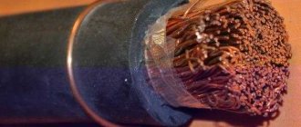
A heat-resistant cable is an electrical conductor enclosed in a sheath of heat-resistant material. This insulation is specially made for the operation of wires and cables in rooms with high temperatures. The insulation is halogen-free, resulting in low smoke emissions. The sheath of these cables and wires is environmentally friendly.
Technical indicator of the product
The RKGM wire has the following characteristics:
- Rated alternating voltage - up to 660 V.
- The cross-section of the stranded core is from 0.75 to 120 square millimeters.
- Flexibility class - from 4 and more.
- The smallest bending radius during installation work is double.
- The operating temperature range is from minus 60 to plus 180 degrees Celsius. The gasket temperature should not be less than 15 degrees below zero.
- The warranty period is 8 years.
- Resistant to fire.
Kinds
What types are there?
Before moving on to discussing types of products, it is necessary to study their main advantages:
- Possibility of operation at high temperature loads.
- High mechanical strength.
- Fire resistance.
- High resistance to corrosion.
- Ability to work in aggressive environments.
- Maximum safety during operation.
Note! Heat-resistant cables and wires for electric furnaces are exposed to high temperatures. They can also be used in grills, heaters, infrared dryers and other equipment.
Manufacturers produce several types of products.
Decoding of the RKGM conductor
Wire RKGM
As a rule, RKGM (marking) is deciphered as follows:
- The letter “A” is missing at the beginning, which means copper wires;
- P - rubber insulation, and its type is organosilicon, as evidenced by the next letter “K”;
- G - the cable is flexible;
- M - outer fiberglass braid. For additional protection, the manufacturer uses heat-resistant silicone varnish and enamel.
Heat resistant conductor MVV
Heat-resistant wire MVV
Scope of application of this type of product:
- heating elements (clamp, cartridge, etc.)
- any electrothermal equipment (furnaces, drying ovens, etc.)
Has the following technical characteristics:
- Long-term operating temperature: from −60 to +500 degrees. Briefly up to +700 degrees.
- The maximum operating temperature of conductors made of 99.20% nickel is +600 degrees.
- Rated supply voltage: 300/500 V.
- Test supply voltage: 2500 V.
- Non-flammable up to +500 degrees.
- Does not ignite if placed in an open fire.
How to decipher the PRKA conductor
PRKA
This abbreviation can be deciphered as follows:
- P - wire made of copper material,
- RK - for reliability and protection of insulation, it is impregnated with anti-rot lubricant,
- A - this letter characterizes high hardness.
This type of wire is used when connecting electric heating devices and electric motors.
The insulator does not contain halogens. It is resistant to fungus and mold. This type of wire is so effective that it is difficult to destroy even when exposed to extreme ultraviolet rays. PRKA does not emit gases. This insulation helps maintain performance when temperatures reach 180 degrees. In addition to this indicator, the humidity level is also taken into account, which should be up to 98%.
What temperature can they withstand?
The term “permissible cable heating temperature” most often refers to a parameter that determines the operating temperature conditions at which the insulation retains its durability and practical qualities. However, when choosing a cable, it is worth using a broader approach, that is, also taking into account the heating temperature of the cores.
In the first case, the ambient temperature is implied, in the second - the heating of the cable itself, caused by the electrical resistance of the current-carrying conductors.
When exposed to excessive heating or cooling, the insulation can begin to deteriorate. This can lead to damage to the cable, as well as devices and mechanisms connected to it. As a result, the permissible heating temperature of wires and cables depends on the insulation material.
“Ordinary” cables with plastic (PVC, polyethylene, polymers), paper, rubber insulation for operation at temperature conditions from −50 to +50 degrees Celsius. When this value is exceeded, the shell and insulation material begins to degrade to the point of melting. Supercooling leads to mechanical destruction of the insulation - the appearance of cracks, breaks and other defects.
For example, the permissible heating temperature of the VVGng cable in the standard version during operation is +50°C, the minimum is −50°C, and for a cable in the design of which PVC plastic with increased cold resistance is used can withstand temperatures up to −60°C inclusive.
Important! If you plan to operate the cable in more extreme temperature conditions, it is advisable to consider specialized models with insulation made of other materials - fluoroplastic, silicone and others. In addition, when operating in extremely cold conditions, cold-resistant versions are suitable.
Product selection
Requirements for cables according to PUE (Electrical Installation Rules)
Requirements for cables are given in Chapter 1.3 PUE 6 (Rules for electrical installations in the sixth edition). In PUE 7, this chapter was included from PUE 6 without changes.
Chapter 1.3 “SELECTION OF CONDUCTORS BY HEATING, ECONOMIC CURRENT DENSITY AND ACCORDING TO CORONA CONDITIONS” applies to the selection of cross-sections of electrical conductors (bare and insulated wires, cables and busbars) by heating, economic current density and corona conditions. If the cross-section of the conductor determined according to these conditions is less than the cross-section required by other conditions (thermal and electrodynamic resistance to short-circuit currents, voltage losses and deviations, mechanical strength, overload protection), then the largest cross-section required by these conditions should be accepted.
Let us highlight the provisions of this chapter that relate to the most commonly encountered and used wires, cords and cables with polyvinyl chloride and rubber insulation.
SELECTION OF CONDUCTOR SECTIONS FOR HEATING
1.3.2. Conductors for any purpose must meet the requirements for maximum permissible heating, taking into account not only normal, but also post-emergency conditions, as well as conditions during repairs and possible uneven distribution of currents between lines, bus sections, etc. When testing for heating, a half-hour maximum current is taken, the largest of the average half-hour currents of a given network element.
1.3.3. For intermittent and short-term operating modes of electrical receivers (with a total cycle duration of up to 10 minutes and an operating period of no more than 4 minutes), the current reduced to the long-term mode should be taken as the calculated current for checking the cross-section of heating conductors. Wherein:
1) for copper conductors with a cross-section of up to 6 mm2, and for aluminum conductors up to 10 mm2, the current is taken as for installations with long-term operation;
2) for copper conductors with a cross-section of more than 6 mm2, and for aluminum conductors with a cross-section of more than 10 mm2, the current is determined by multiplying the permissible continuous current by a factor of 0.875/√Tp.v. , where Тп.в is the duration of the working period expressed in relative units (the duration of switching on in relation to the duration of the cycle).
1.3.4. For a short-term operating mode with a switching duration of no more than 4 minutes and breaks between switching on sufficient to cool the conductors to ambient temperature, the maximum permissible currents should be determined according to the standards for intermittent duty (see 1.3.3). When the duration of switching on is more than 4 minutes, as well as during breaks of insufficient duration between switching on, the maximum permissible currents should be determined as for installations with long-term operating mode.
1.3.6. For the period of liquidation of the post-emergency regime, an overload of up to 10% is allowed for cables with polyethylene insulation, and for cables with polyvinyl chloride insulation up to 15% of the rated load during peak loads lasting no more than 6 hours per day for 5 days, if the load during the remaining periods of time of these days is not exceeds nominal.
1.3.7. The requirements for normal loads and post-accident overloads apply to cables and the connecting and termination couplings and terminations installed on them.
1.3.8. Zero working conductors in a four-wire three-phase current system must have a conductivity of at least 50% of the conductivity of the phase conductors; if necessary, it should be increased to 100% of the conductivity of the phase conductors.
1.3.9. When determining permissible long-term currents for cables, bare and insulated wires and busbars, as well as for rigid and flexible conductors laid in an environment whose temperature differs significantly from that given in 1.3.12 - 1.3.15 and 1.3.22, coefficients should be applied, given in table. 1.3.3.
Table 1.3.3. Correction factors for currents for cables, bare and insulated wires and busbars depending on ground and air temperatures
| Conditional temp. environment, °C | Normir. pace. lived, °C | Correction factors for currents at the design temperature of the environment, °C | |||||||||||
| -5 and below | 0 | +5 | +10 | +15 | +20 | +25 | +30 | +35 | +40 | +45 | +50 | ||
| 15 | 80 | 1,14 | 1,11 | 1,08 | 1,04 | 1,00 | 0,96 | 0,92 | 0,88 | 0,83 | 0,78 | 0,73 | 0,68 |
| 25 | 80 | 1,24 | 1,20 | 1,17 | 1,13 | 1,09 | 1,04 | 1,00 | 0,95 | 0,90 | 0,85 | 0,80 | 0,74 |
| 25 | 70 | 1,29 | 1,24 | 1,20 | 1,15 | 1,11 | 1,05 | 1,00 | 0,94 | 0,88 | 0,81 | 0,74 | 0,67 |
| 15 | 65 | 1,18 | 1,14 | 1,10 | 1,05 | 1,00 | 0,95 | 0,89 | 0,84 | 0,77 | 0,71 | 0,63 | 0,55 |
| 25 | 65 | 1,32 | 1,27 | 1,22 | 1,17 | 1,12 | 1,06 | 1,00 | 0,94 | 0,87 | 0,79 | 0,71 | 0,61 |
| 15 | 60 | 1,20 | 1,15 | 1,12 | 1,06 | 1,00 | 0,94 | 0,88 | 0,82 | 0,75 | 0,67 | 0,75 | 0,47 |
| 25 | 60 | 1,36 | 1,31 | 1,25 | 1,20 | 1,13 | 1,07 | 1,00 | 0,93 | 0,85 | 0,76 | 0,66 | 0,54 |
| 15 | 55 | 1,22 | 1,17 | 1,12 | 1,07 | 1,00 | 0,93 | 0,86 | 0,79 | 0,71 | 0,61 | 0,50 | 0,36 |
| 25 | 55 | 1,41 | 1,35 | 1,29 | 1,23 | 1,15 | 1,08 | 1,00 | 0,91 | 0,82 | 0,71 | 0,58 | 0,41 |
| 15 | 50 | 1,25 | 1,20 | 1,14 | 1,07 | 1,00 | 0,93 | 0,84 | 0,76 | 0,66 | 0,54 | 0,37 | — |
| 25 | 50 | 1,48 | 1,41 | 1,34 | 1,26 | 1,18 | 1,09 | 1,00 | 0,89 | 0,78 | 0,63 | 0,45 | — |
1.3.10. Permissible long-term currents for wires with rubber or polyvinyl chloride insulation, cords with rubber insulation and cables with rubber or plastic insulation in lead, polyvinyl chloride and rubber sheaths x are given in table. 1.3.4 - 1.3.11. They are accepted for temperatures: cores +65 °C, ambient air +25 °C and ground +15 °C.
When determining the number of wires laid in one pipe (or cores of a stranded conductor), the neutral working conductor of a four-wire three-phase current system, as well as grounding and neutral protective conductors are not taken into account.
The data contained in the table. 1.3.4 and 1.3.5 should be applied regardless of the number of pipes and the location of their installation (in the air, floors, foundations).
Permissible long-term currents for wires and cables laid in boxes, as well as in trays in bundles, must be accepted: for wires - according to table. 1.3.4 and 1.3.5, as for wires laid in pipes, for cables - according to table. 1.3.6 - 1.3.8, as for cables laid in the air. If the number of simultaneously loaded wires is more than four, laid in pipes, boxes, and also in trays in bundles, the currents for the wires should be taken according to the table. 1.3.4 and 1.3.5, as for wires laid openly (in the air), with the introduction of reduction factors of 0.68 for 5 and 6; 0.63 for 7 - 9 and 0.6 for 10 - 12 wires.
For secondary circuit wires, reduction factors are not introduced.
1.3.11. Permissible long-term currents for wires laid in trays for single-row installation (not in bundles) should be taken as for wires laid in the air.
Permissible long-term currents for wires and cables laid in boxes should be taken according to table. 1.3.4 - 1.3.7, as for single wires and cables laid openly (in the air), using the reduction factors indicated in table. 1.3.12.
When choosing reduction factors, control and reserve wires and cables are not taken into account.
Table 1.3.4. Permissible continuous current for wires and cords with rubber and polyvinyl chloride insulation with copper conductors
| Cross-section of current-carrying conductor, mm2 | Current, A, for wires laid | |||||
| open | in one pipe | |||||
| two single-core | three single-core | four single-core | one two-wire | one three-wire | ||
| 0,5 | 11 | — | — | — | — | — |
| 0,75 | 15 | — | — | — | — | — |
| 1 | 17 | 16 | 15 | 14 | 15 | 14 |
| 1,2 | 20 | 18 | 16 | 15 | 16 | 14,5 |
| 1,5 | 23 | 19 | 17 | 16 | 18 | 15 |
| 2 | 26 | 24 | 22 | 20 | 23 | 19 |
| 2,5 | 30 | 27 | 25 | 25 | 25 | 21 |
| 3 | 34 | 32 | 28 | 26 | 28 | 24 |
| 4 | 41 | 38 | 35 | 30 | 32 | 27 |
| 5 | 46 | 42 | 39 | 34 | 37 | 31 |
| 6 | 50 | 46 | 42 | 40 | 40 | 34 |
| 8 | 62 | 54 | 51 | 46 | 48 | 43 |
| 10 | 80 | 70 | 60 | 50 | 55 | 50 |
| 16 | 100 | 85 | 80 | 75 | 80 | 70 |
| 25 | 140 | 115 | 100 | 90 | 100 | 85 |
| 35 | 170 | 135 | 125 | 115 | 125 | 100 |
| 50 | 215 | 185 | 170 | 150 | 160 | 135 |
| 70 | 270 | 225 | 210 | 185 | 195 | 175 |
| 95 | 330 | 275 | 255 | 225 | 245 | 215 |
| 120 | 385 | 315 | 290 | 260 | 295 | 250 |
| 150 | 440 | 360 | 330 | — | — | — |
| 185 | 510 | — | — | — | — | — |
| 240 | 605 | — | — | — | — | — |
| 300 | 695 | — | — | — | — | — |
| 400 | 830 | — | — | — | — | — |
Table 1.3.5. Permissible continuous current for rubber and polyvinyl chloride insulated wires with aluminum conductors
| Cross-section of current-carrying conductor, mm2 | Current, A, for wires laid | |||||
| open | in one pipe | |||||
| two single-core | three single-core | four single-core | one two-wire | one three-wire | ||
| 2 | 21 | 19 | 18 | 15 | 17 | 14 |
| 2,5 | 24 | 20 | 19 | 19 | 19 | 16 |
| 3 | 27 | 24 | 22 | 21 | 22 | 18 |
| 4 | 32 | 28 | 28 | 23 | 25 | 21 |
| 5 | 36 | 32 | 30 | 27 | 28 | 24 |
| 6 | 39 | 36 | 32 | 30 | 31 | 26 |
| 8 | 46 | 43 | 40 | 37 | 38 | 32 |
| 10 | 60 | 50 | 47 | 39 | 42 | 38 |
| 16 | 75 | 60 | 60 | 55 | 60 | 55 |
| 25 | 105 | 85 | 80 | 70 | 75 | 65 |
| 35 | 130 | 100 | 95 | 85 | 95 | 75 |
| 50 | 165 | 140 | 130 | 120 | 125 | 105 |
| 70 | 210 | 175 | 165 | 140 | 150 | 135 |
| 95 | 255 | 215 | 200 | 175 | 190 | 165 |
| 120 | 295 | 245 | 220 | 200 | 230 | 190 |
| 150 | 340 | 275 | 255 | — | — | — |
| 185 | 390 | — | — | — | — | — |
| 240 | 465 | — | — | — | — | — |
| 300 | 535 | — | — | — | — | — |
| 400 | 645 | — | — | — | — | — |
Table 1.3.6. Permissible continuous current for wires with copper conductors with rubber insulation in metal protective sheaths and cables with copper conductors with rubber insulation in lead, polyvinyl chloride, nayrite or rubber sheaths, armored and unarmored
| Conductor cross-section, mm2 | Current*, A, for wires and cables | ||||
| single-core | two-wire | three-wire | |||
| when laying | |||||
| in the air | in the air | in the ground | in the air | in the ground | |
| 1,5 | 23 | 19 | 33 | 19 | 27 |
| 2,5 | 30 | 27 | 44 | 25 | 38 |
| 4 | 41 | 38 | 55 | 35 | 49 |
| 6 | 50 | 50 | 70 | 42 | 60 |
| 10 | 80 | 70 | 105 | 55 | 90 |
| 16 | 100 | 90 | 135 | 75 | 115 |
| 25 | 140 | 115 | 175 | 95 | 150 |
| 35 | 170 | 140 | 210 | 120 | 180 |
| 50 | 215 | 175 | 265 | 145 | 225 |
| 70 | 270 | 215 | 320 | 180 | 275 |
| 95 | 325 | 260 | 385 | 220 | 330 |
| 120 | 385 | 300 | 445 | 260 | 385 |
| 150 | 440 | 350 | 505 | 305 | 435 |
| 185 | 510 | 405 | 570 | 350 | 500 |
| 240 | 605 | — | — | — | — |
* Currents apply to wires and cables both with and without a neutral core.
Table 1.3.7. Permissible continuous current for cables with aluminum conductors with rubber or plastic insulation in lead, polyvinyl chloride and rubber sheaths, armored and unarmored
| Conductor cross-section, mm2 | Current, A, for cables | ||||
| single-core | two-wire | three-wire | |||
| when laying | |||||
| in the air | in the air | in the ground | in the air | in the ground | |
| 2,5 | 23 | 21 | 34 | 19 | 29 |
| 4 | 31 | 29 | 42 | 27 | 38 |
| 6 | 38 | 38 | 55 | 32 | 46 |
| 10 | 60 | 55 | 80 | 42 | 70 |
| 16 | 75 | 70 | 105 | 60 | 90 |
| 25 | 105 | 90 | 135 | 75 | 115 |
| 35 | 130 | 105 | 160 | 90 | 140 |
| 50 | 165 | 135 | 205 | 110 | 175 |
| 70 | 210 | 165 | 245 | 140 | 210 |
| 95 | 250 | 200 | 295 | 170 | 255 |
| 120 | 295 | 230 | 340 | 200 | 295 |
| 150 | 340 | 270 | 390 | 235 | 335 |
| 185 | 390 | 310 | 440 | 270 | 385 |
| 240 | 465 | — | — | — | — |
Note. Permissible continuous currents for four-core cables with plastic insulation for voltages up to 1 kV can be selected according to table. 1.3.7, as for three-core cables, but with a coefficient of 0.92.
Table 1.3.8. Permissible continuous current for portable light and medium hose cords, portable heavy duty hose cables, mine flexible hose cables, floodlight cables and portable wires with copper conductors
| Conductor cross-section, mm2 | Current*, A, for cords, wires and cables | ||
| single-core | two-wire | three-wire | |
| 0,5 | — | 12 | — |
| 0,75 | — | 16 | 14 |
| 1,0 | — | 18 | 16 |
| 1,5 | — | 23 | 20 |
| 2,5 | 40 | 33 | 28 |
| 4 | 50 | 43 | 36 |
| 6 | 65 | 55 | 45 |
| 10 | 90 | 75 | 60 |
| 16 | 120 | 95 | 80 |
| 25 | 160 | 125 | 105 |
| 35 | 190 | 150 | 130 |
| 50 | 235 | 185 | 160 |
| 70 | 290 | 235 | 200 |
* Currents apply to cords, wires and cables with and without a neutral core.
Table 1.3.9. Permissible continuous current for portable hose cables with copper conductors and rubber insulation for peat enterprises
| Conductor cross-section, mm2 | Current*, A, for cables with voltage, kV | ||
| 0,5 | 3 | 6 | |
| 6 | 44 | 45 | 47 |
| 10 | 60 | 60 | 65 |
| 16 | 80 | 80 | 85 |
| 25 | 100 | 105 | 105 |
| 35 | 125 | 125 | 130 |
| 50 | 155 | 155 | 160 |
| 70 | 190 | 195 | — |
* Currents refer to cables with and without a neutral core.
Table 1.3.10. Permissible continuous current for hose cables with copper conductors and rubber insulation for mobile electrical receivers
| Conductor cross-section, mm2 | Current*, A, for cables with voltage, kV | Conductor cross-section, mm2 | Current*, A, for cables with voltage, kV | ||
| 3 | 6 | 3 | 6 | ||
| 16 | 85 | 90 | 70 | 215 | 220 |
| 25 | 115 | 120 | 95 | 260 | 265 |
| 35 | 140 | 145 | 120 | 305 | 310 |
| 50 | 175 | 180 | 150 | 345 | 350 |
* Currents refer to cables with and without a neutral core.
Table 1.3.11. Permissible continuous current for wires with copper conductors with rubber insulation for electrified transport 1.3 and 4 kV
| Conductor cross-section, mm2 | Current, A | Conductor cross-section, mm2 | Current, A | Conductor cross-section, mm2 | Current, A |
| 1 | 20 | 16 | 115 | 120 | 390 |
| 1,5 | 25 | 25 | 150 | 150 | 445 |
| 2,5 | 40 | 35 | 185 | 185 | 505 |
| 4 | 50 | 50 | 230 | 240 | 590 |
| 6 | 65 | 70 | 285 | 300 | 670 |
| 10 | 90 | 95 | 340 | 350 | 745 |
Table 1.3.12. Reduction factor for wires and cables laid in boxes
| Laying method | Number of laid wires and cables | Reduction factor for wires and cables supplying | ||
| single-core | stranded | separate electrical receivers with a utilization factor of up to 0.7 | groups of electrical receivers and individual receivers with a utilization factor of more than 0.7 | |
| Multilayered and bundled | — | Up to 4 | 1,0 | — |
| 2 | 5-6 | 0,85 | — | |
| 3-9 | 7-9 | 0,75 | — | |
| 10-11 | 10-11 | 0,7 | — | |
| 12-14 | 12-14 | 0,65 | — | |
| 15-18 | 15-18 | 0,6 | — | |
| Single layer | 2-4 | 2-4 | — | 0,67 |
| 5 | 5 | — | 0,6 | |
Cable VVG, VVGng(A), VVGng(A)-LS decoding and differences according to GOST
Color of conductors in the cable according to PUE 7, GOST R 50462 and GOST 31996
Color chart for cable cores according to GOST R 50462-2009
How to choose the right one
When choosing a cable, you need to take into account all the requirements. Not only the reliability of electrical wiring, but also safety depends on the right decision. The peculiarity of the bath rooms is the temperature increase up to +160°C, as well as the humidity level up to 80%. Based on this data, you need to select the appropriate cable that will meet all the requirements.
You might be interested in this: What is a main switchboard, how does it stand for?
Both a bathhouse and a sauna usually include more than one object, each of which has its own specific temperature regime. Accordingly, for each object you need to select the appropriate product. To install a lighting network in the dressing room, you can use conventional wiring of the PVS, VVG, AVVG or NYM categories.
Note! For wooden objects, even a regular cable should be protected with a plastic box, despite the fact that the room is almost dry. Domestic cables of the brands PPGng-HF 3*1.5, VVGng-LS 3*1.5 or NYM 3*1.5 are suitable for the first group of premises - for wiring lighting in dressing rooms. For sockets, it is better that the wire cross-section is at least 2.5 sq. mm.
The second group of premises is the bathhouse or sauna itself. This is where a special heat-resistant cable is needed. Among the domestic options, the following are suitable: three RKGM 1*2.5, PVKV 1*2.5, PRKA 1*2.5 or PAL 1*2.5, or three-core PMTC 3*2.5, PNBS 3*2.5 or PRKS 3*2.5. The wiring must have protective grounding.
Cable Application
Area of cable use
Thanks to the wide range, choosing products for specific purposes is quite simple. It is successfully used in industry and everyday life, outdoors and indoors. Therefore, the cable is often used in tropical heat and temperate climate zones.
Important! In residential construction, this brand of wire is used for electrical wiring in bathrooms and in the construction of baths and saunas.
Industrial enterprises use wire to connect powerful machines to the electrical wiring system and the main power source. It is used for the manufacture of windings in the production of large electrical equipment.
It is widely used in chemical plants, since the insulating materials are not afraid of the effects of varnishes and paints that can get on the surface of the cable. Since the rubber is impregnated with a layer of varnish, the outer winding does not dissolve under the influence of aggressive environments and remains intact. This ensures stable operation of the entire electrical system.
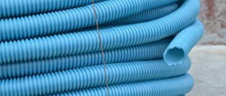
In conclusion, it should be noted that this type of cables and wires has a long service life. For additional protection, heat-resistant wires and cables can be equipped with flexible heat-resistant metal braiding with a diameter of 3 or 6 mm.