In the absence of special devices, two methods are mainly used:
- cartographic
- external identification marks
However, it can be difficult to determine the exact location of the cable route from them. Errors often occur due to the human factor.
But outdoor signs are not durable and are often damaged by unauthorized persons.
Moreover, even with a route finder, sometimes there are a lot of nuances in identifying a particular cable in dense urban areas.
The so-called “dirty air” is when communication cables or power cables laid in parallel, as well as communication pipes, generate significant interference.
Ultimately, the slightest mistake can result in huge costs and long-term equipment downtime.
To prevent this from happening, they came up with electronic marking of underground cable lines and other communication networks (each at its own frequency).
However, do not be confused, such intelligent marking is just an addition to existing methods of detecting and marking a route. And under no circumstances should we refuse them.
Finding a broken hidden wiring in a concrete wall
A special device - a locator - will help you find the location of a wire break in a concrete wall. It is a combination of a receiver and an oscillator. This method can be associated with the induction method in searching for cable faults underground.
So, determining the location of the break with a route finder is not difficult. The end of the wire in which there is a break is connected to a generator, which sends pulses of a certain frequency into it. By passing the frame over the place where the wiring is laid, the sound that is formed as a result of the influence of impulses will be clearly audible in the headphones. As soon as the sound disappears, mark this place on the wall - this will be the point of damage to the wire.
A non-contact voltage indicator will also help you find a break in a phase wire. Everything is simple here. We move the device along the wall until the voltage indicator stops lighting. We run the device several times in a circle in this area of the wall to make sure that we have not left the route of the wires. The absence of light on the indicator will indicate the approximate location of the break.
In conclusion, I would like to note that a locator and a non-contact voltage indicator can be used to search for damage to wiring under plaster or under drywall.
Finally, we recommend watching a useful video on finding short circuits in wiring:
So we looked at the most well-known methods for finding the location of cable damage. We hope the information was useful and interesting for you!
We also recommend reading:
Passive method
If the power cable is under load, voltage is applied to it and electric current flows through it, the use of a passive location method is allowed. An electric current flowing through the cores of a power cable creates an electromagnetic field around it with a frequency of 50 Hz. This field can be detected by the locator receiver. In this case, the locator generator is not used at all. This method is simple, but not always effective. With its help, it is easy to determine that there is a cable underground, but it is impossible to distinguish one cable from another. The signal from all power cables will have the same frequency.
Passive location method
Determining the distance to the location of cable damage underground
Determining the distance to the defect is carried out using one of two methods - reflectometric (using reflectometers) and bridge (using cable bridges). These methods have significant differences.
Cable bridges localize damage based on cable resistance and capacitance. During the measurement, they use auxiliary (known good) conductors or cable pairs, which allows them to measure the resistance (capacitance) of the good pair, compare these readings with similar values on the damaged pair and determine the distance to the defect. During measurements, they most often use a voltage of 180V - 500V, which makes it possible to determine even minor damage to the cable insulation.
Cable reflectometers send a pulse with an amplitude of approximately 20V to the pair (the pulse width is adjusted depending on the length of the line) and the type of damage and the distance to it are determined by the shape and delay of the pulses reflected from inhomogeneities (defects). This method will not allow you to detect minor insulation damage, but it will easily detect mixed-up pairs, parallel taps, Pupin coils, etc.
To increase efficiency, these methods are increasingly being combined in one device. In this version, for example, the IRK-PRO Alfa and KB Svyaz Sova devices are presented. The SideKick Plus and Riser Bond 6000DSL analyzers described above also have such functions.
It should be noted that the accuracy of determining the distance to a defect by the device and the accuracy of localizing damage in the cable are different things. After all, the measured distance still needs to be accurately measured, and this is a very difficult task, taking into account the cable reserves on the couplings, the unevenness of the cable depth, etc. In addition, a large error is introduced by inaccurately entered linear values of resistance and capacitance or the propagation coefficient (and they constantly change during operation).
Localization of damage on the ground
Once the approximate distance to the fault is known, a locator or cable locator generator is connected to the damaged pair and cable tracing begins. It is better to start tracing and searching for a defect in a damaged cable at a distance of 200-300 meters from the defect location determined by a cable bridge or reflectometer, from the nearest coupling, cable box or other place whose location is precisely known. Moreover, if the tracing starts from a cable cabinet or box, the generator must be installed in this place.
Tracing and localization of defects can be done in parallel or sequentially. In the first case, the route is first “beaten” using a locator, after which the damage is located using a cable locator. In the second case, tracing and localization of damage is carried out simultaneously: one specialist traces the line, the other - localizes the damage. For such cases, there are devices with one generator but two receivers, for example Search-310D-2M (2). There are also devices that combine not only means of searching and localizing damage, but also means of preliminary diagnostics and determining the distance to damage. Among them, we can highlight the ToneRanger device from Greenlee. Its advantages include:
- High accuracy of damage localization
- No dependence of diagnostic results on the length and temperature of the cable, the difference in the cross-section of the cores of different sections, the number of sections, the presence of water in the cable and couplings
- Measuring parameters such as:
- Insulation resistance
- Loop resistance
- Capacity
- Determining the distance to damage
- Localization of damage:
- Reduced insulation resistance
- Short circuit
- Break
- Confused couples
- Cable pair identification
- During measurements, it does not affect the transmission of information in adjacent DSL lines
- All-weather vibration and shock resistant design
Cable routing is described in detail in the section “Routing and identification of utilities (cables, pipelines, etc.)”, so we will not dwell on it here. Already during tracing, it is possible to localize some cable damage, such as a break or short circuit of a pair.
Localization of damage to cable insulation, as mentioned above, is carried out using a cable locator. Its components are contact pins (or, as shown in the figure, an A-frame) and a signal generator.
The generator is connected to the line and supplies high voltage pulses to it. Localization is done using contact pins or an A-frame with indicators. The A-frame consists of two contact pins connected to each other, measuring the potential difference at a point, finding where the current leaks into the ground. The leak point is determined after disconnecting the cable from the standard ground. A grounded generator is connected to the screen or core of the cable, creating conditions for the return of the “drained” current through the least resistance. The contact pins or A-frame are moved parallel to the cable line (above it), in the direction of the suspected damage, periodically sticking it into the ground, checking the indicator readings.
Depending on the location of the defect in relation to the A-frame (contact pins) and the generator, the voltmeter readings fluctuate to the right or left of zero (plus and minus, respectively). A shift of the indicator to a plus scale indicates that the cable damage is located between the A-frame and the end of the cable, and a shift to minus indicates that the device is between the generator and the A-frame. By moving the A-frame towards the damage, the location at which the indicator will show the opposite direction is determined. Having turned the frame 90 degrees, moving towards the defect, you need to find the next point at which the indicator will show the opposite direction. If the arrow is in the middle of “0”, this means that the insulation damage is located directly between the points of contact with the ground (A-frames). This point is the search target.
When localizing damage, the receiver readings may vary depending on the depth of the cable, heterogeneity of the soil (dry or wet, sand or clay) and the presence of metal objects directly near the line. In order not to be distracted by searching for such “problems”, you need to consider the following:
- near the damage, the indicator readings change sharply at one point;
- the value of the maximum indicator readings should be correlated with the value of damage resistance;
- Leakage can be checked “to a minimum” by inserting the pins at a greater distance from each other (if there are several damages nearby, this method is not suitable).
Damage to cable lines: methods and methods of detection
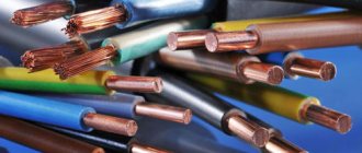
Most large electrical connections between energy consumers and sources are made using cable lines. Most often this is a system of cables, couplings and fasteners parallel to each other. Damage, even to the smallest extent, is fraught with at least economic losses.
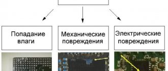
Most common damage
Cable lines can be laid underground or above ground. In this case, the nature of their damage will be similar. Most often the following happens:
- one or more cores may be damaged. In this case, the circuit is made to the ground;
- several wires are damaged with a short circuit to each other;
- grounding cable break;
- gap without grounding;
- the occurrence of a so-called “floating breakdown”, when a short circuit occurs when the voltage increases, after normalization the situation stabilizes;
- the integrity of the insulating layer is damaged.
Any damage requires immediate repair. As power supply patterns are disrupted, the reliability of the entire power supply to end users is called into question. This also affects the technical and economic indicators of the entire network as a whole.
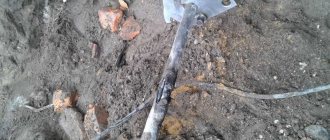
The photo shows that we are dealing with a low-Ohm breakdown; such a place of damage is the easiest to find.
The causes of damage may be:
- In different seasons, soil movement occurs. For example, in the spring, as a result of sudden thawing of individual sections, the lines may experience excessive tension, which leads to rupture;
- violation of supply conditions, in particular overcurrent;
- violations in line laying technology;
- work near lines that violate boundaries;
- lines may be exposed to transit currents.
What is electronic tagging?
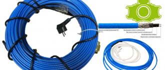
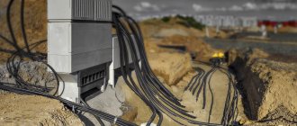
What is the essence of electronic cable marking? Everything is very simple. Initially during the construction period, a special marker is placed next to the existing communication line - an “orange” in a protective plastic casing.
This marker is easily determined from the surface of the earth with a sounding device. The search tool generates a signal, which causes response oscillations of a certain frequency in the marker, which are recorded on the screen.
These things are especially effective in places where couplings are installed and on road turns.
There is no need to apply any voltage to the marker or connect it to anything.
Imagine that from now on, when tracing a line, you no longer have to:
1Go to the transformer substation or substation to disconnect and unplug the ends of the cable. 2Switch the consumer to the backup cable line.
3Connect the generator to the conductors.
4Wander randomly around the city with headphones on and try to hear a squeak from the signal source among the extraneous noise.
5Dig a hole to find out the depth.
Your labor costs will be reduced by at least 50%. Here is a real calculation and comparison of similar work performed at one of the branches of OJSC “MOESK”.
The service life of the marker is 50 years and above. Individual specimens can be buried to a depth of 2.4 m and they will be perfectly audible.
True, it is always recommended to secure them with a cable to avoid movement when the ground moves.
The signal spot from them on the surface reaches 2 meters.
Briefly about cable line repair
Repair work on cable lines is usually classified into planned and emergency. As for the volume of such work, for the former it is, as a rule, capital, for the latter it is current.
During major works, planned replacement of cable lines, laying of new routes, etc. are carried out. If necessary, repairs and/or upgrades of related equipment are also performed. The latter include ventilation systems and lighting for cable tunnels, as well as pumps for pumping out groundwater. Considering the specifics of planned work, localization of defective areas is not required during their implementation.
The situation is completely different during emergency repairs. In order not to dig up the entire route, you should accurately determine the location of the wire break, insulation breakdown, etc. For this purpose, various methods are used, for which special equipment is used. This will be discussed in detail below.
The photo shows a dead-end coupling MT-45. Designed to protect splices of TPP and TPPep cables with a capacity of 10 to 50 pairs with conductors with a diameter of 0.32 to 0.5 mm. The coupling consists only of a polyethylene body in the form of a polyethylene tube, plugged on one side. The method of installing TPP and TPPep cables in the MT-45 coupling consists of connecting the cores and screens of the parallel connected ends of the cables, placing them in the coupling body and then filling the coupling with self-expanding polyurethane sealant VILAD-31. It’s just that it was clearly installed without the use of VILAD-31 sealant, but with the help of an incomprehensible white mass, more like soap or grease. And, of course, blue electrical tape. It is known that in any unclear situation you should use blue electrical tape - this is the “key to success.” The result of such installation of a coupling connection is in front of you.
Locators:
When providing services, we AT THE SAME TIME use the most informative equipment made in the USA and UK, Radiodetection 2000 and RIDGID SR-20 locators. The first has a higher sensitivity, the second allows you to determine the route with an accuracy of 5 cm, as well as the depth (up to 12 meters in depth).
In addition to finding the route, we also determine the depth of underground communications.
How to find the location of cable damage?
During operation and at the stage of installation of cable lines laid underground, unexpected mechanical damage to the insulation and current-carrying conductors occurs. This may be due to a violation of normal operating conditions, careless installation work on other communications located a few meters from the installation site and not related to the power supply line. We will further describe how to search for cable damage underground and in the wall, providing existing methods and instruments for detecting the faulty area.
To find the location of the cable line damage, you need to understand the specifics and methodology of the search. The process must be divided into two stages:
- Search for problem areas along the entire length of the line.
- Searching for an accident site on a designated section of the highway.
There are several methods for finding the damaged area:
- Pulse method;
- Loop method;
- Acoustic method;
- Induction method;
- Step voltage method.
Pulse method.
This method involves searching for damage using a reflectometer. The operation of the device is based on sending probing pulses of a certain frequency, which, when encountering an obstacle in their path, are reflected and returned back to the device. That is, the device is located at one end of the power cable, which is very convenient and practical. Tests should be carried out on a completely disconnected line.
Loop method.
This method is applicable provided that at least one wire in the cable remains intact, or another conductor with intact cores lies nearby. To find out the distance to the place of damage using the loop method, you need to measure the DC resistance of the wires with the P333 device. This is a DC measuring bridge. This is one of the first methods invented to find the location of the fault, and it is used exclusively for single-phase and two-phase faults. Gradually they stop using it, due to its labor intensity and large error in measurements.
Acoustic method.
You can find a break in a cable using the acoustic method by creating a discharge at the damage site using a high-voltage pulse generator. At the location of the break or short circuit, sound vibrations of a certain frequency will appear. The quality of listening depends on the type of soil, the distance from the surface to the cable line and the type of damage. A prerequisite for the method to work is to exceed the contact resistance value of 40 ohms.
Step voltage method.
The method is based on passing current generated by a generator through a cable. It creates a potential difference between two points located in the ground, which can be judged by the current leakage at the site of the accident. To find a point with reduced insulation resistance, contact probe probes are installed like this - the first one is exactly above the running conductor, the second one is at an angle of 90, a meter from the first one.
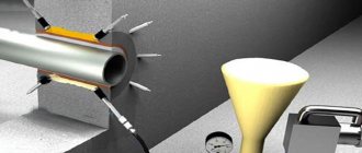
Induction method.
The method very accurately determines the location of the break, but its use is associated with burning the cable. If the transition resistance is high, it is necessary to reduce its value by burning using special devices. The method is based on passing a high-frequency current through the core, which forms an electromagnetic field above the cable line. In places of mechanical damage to the route, passing the receiving frame, the sound will change. Thus, the absence of sound indicates a wire break.
A special device - a locator - will help you find the location of a wire break in a concrete wall. It is a combination of a receiver and an oscillator. This method can be associated with the induction method in searching for cable faults underground.
Cost of services
We provide services throughout Moscow and the Moscow region.
| Finding hidden cables in the ground | from 9,000 rubles * |
| Cable routing | from 9,000 rubles * |
* The minimum cost of visiting sites located in Moscow and the Moscow region up to 10 km from the Moscow Ring Road is 9,000 rubles, more than 10 km from the Moscow Ring Road – 12,000 rubles.
You can get detailed advice on the cost of services by calling 8(495) 230-54-20 . Do not doubt! Order a service from the professionals of the Locator-PLUS company.
Methods for finding the location of cable damage
The following methods have been developed and successfully used to search for damage sites.
Pulse method
The pulse method is excluded from use in case of floating breakdowns due to the fact that the cause of such damage is high humidity; therefore, the conductor resistance exceeds 150 Ohms, and this is unacceptable for this method.
The check is carried out in accordance with the instructions provided on how to find the location of the damage, using an IKL-5 or IKL-4 meter by introducing a pulse through alternating current to the fault area and receiving a response signal. The device measures the time between the period of delivery and the return of the pulse.
Acoustic method
The acoustic method involves the use of a receiver and an electric generator of powerful shock pulses. The generator capacitor is connected to the cable, and when the spark gap is triggered, the voltage in the line creates an electromagnetic wave, and strong penetration occurs, accompanied by a click in the fault area. The operator detects clicks using an acoustic device.
The sound propagation zone ranges from two to fifteen meters. The point of cable failure is determined by the presence of the loudest possible sound.
Loop method
Faults are determined by comparing the resistances of the broken and intact cable cores using the loop method. The procedure for searching for damage in this case requires the formation of a bridge of type R 334 or R 333 from the cable, and the presence of an MVU-49 resistance bridge is also required.
It is used if one cable core is not damaged; if all cores are faulty, it is recommended to use an undamaged core of a nearby cable channel.
The good and damaged cores are connected on one side of the cable in a loop. A bridge is installed on the opposite side of the cable to regulate electrical resistance. Measurements are taken and, using resistance ratio formulas, the distance to the fault location is established.
The disadvantage of this method is the inaccuracy of determining the location of the fault and the huge time costs.
Induction method
Let us now consider how to determine the area of cable damage using the induction method, which is more accurate and gives a chance to identify the fault section directly in the cable line; the error of this method does not exceed 50 centimeters.
The use of the induction method is permissible if, at the location of the fault, the transition resistance in the cable line is no more than twenty to fifty ohms.
The content of the method is to capture and fix over the cable channel oscillations of the electromagnetic field formed by passing electricity through the faulty conductor with a sound frequency of 800 to 1000 Hz. The operator moves along the cable route and, using an antenna, amplifier and headphones, determines the nature of the transmission of the electromagnetic field. The sound increases noticeably at the point of failure and loses strength at a distance of 50 centimeters from the point of breakdown.
WHAT WHAT? CONSEQUENCES OF DAMAGE TO COMMUNICATIONS
Damage to cables and any other underground communications is primarily dangerous due to harm to the health and lives of people. Creating an emergency situation on any highway brings serious problems and waste of money.
For example
The fine for damage to a fiber optic communication cable, taking into account downtime of communication channels and loss of profit, is 100,000 - 300,000 rubles. The amount of financial losses in case of damage to an electrical cable is usually greater than the above. Damage to a gas pipe is even more dangerous and costly.