Repairing an electric drill can be done on your own. To do this, you need to know certain types of breakdowns and methods for restoring units. The connection diagram for the electric drill button requires special attention. Malfunctions associated with its operation should also be considered. If you know the intricacies of your instrument, it will be easy to repair it at any time. Before repairing, you should find out which drill button connection diagram is used in a particular model.
Possible faults
If the drill's performance begins to deteriorate, it is worth having it diagnosed. First you need to check the drive for various damages. Also, first of all, the presence of voltage in the network from which the device is powered is checked.
Battery models can be diagnosed using a special device - a tester. The voltage specified by the manufacturer must correspond to the value given by the testing device.
If the voltage is lower, the battery should be replaced. The most common drill malfunctions:
- problems arising when the button mechanism malfunctions;
- engine breakdown;
- brush wear.
If you know how to connect the tool button, you can easily deal with damage associated with this part. It should also be remembered that many problems that arise when operating a drill are associated with dustiness of the device. It should be cleaned after each use. Otherwise, the tool will last much less.
Connection diagram
To check the functionality of a tool, using only a tester is not enough. The main part of the device buttons is equipped with a smooth speed control mechanism. This is why the tester can produce incorrect values. In this case, you should familiarize yourself with the specific button connection diagram.
Often in electric drills there is only 1 wire going to the terminal. Due to this, when the contact is closed by the button, the terminals are tested. In this case, the blinking light means that everything is in order with the button. In the case of a faulty mechanism, the tester will not respond.
When replacing a button, it should be taken into account that the circuit may have a fairly simple structure, or it may be made in reverse. Due to this, each process associated with replacing a tool button must be carried out in accordance with the diagram. Nothing can be added. For example, the size of the new part must be appropriate. Drills with reverse will have to be checked for malfunctions a little longer than simple models.
How Reverse Works on a Drill
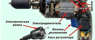
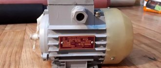
Drill device
Electric motor
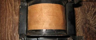
. The commutator electric motor of a drill contains three main elements. stator, armature and carbon brushes. The stator is made of electrical steel with high magnetic permeability. It has a cylindrical shape and grooves for laying stator windings. There are two stator windings and they are located opposite each other. The stator is rigidly mounted in the drill body.
The rotor is a shaft onto which an electrical steel core is pressed. Along the entire length of the core, grooves are machined at equal distances for laying armature windings.
The windings are wound with a solid wire with taps for attachment to the collector plates. Thus, an anchor is formed, divided into segments. The collector is located on the shaft shank and is rigidly mounted on it.
During operation, the rotor rotates inside the stator on bearings located at the beginning and end of the shaft.
Spring-loaded brushes move along the plates during operation. By the way, when repairing a drill, special attention should be paid to them. The brushes are pressed from graphite and have the shape of a parallelepiped with built-in flexible electrodes.
Speed controller
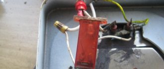
. The drill speed is controlled by a triac regulator located in the power button. It should be noted that there is a simple adjustment scheme and a small number of parts. This regulator is assembled in a button body on a PCB substrate using microfilm technology.
The board itself has miniature dimensions, which made it possible to place it in the trigger housing. Key moment. This is that in the drill regulator (in the triac) the circuit opens and closes in milliseconds.
And the regulator does not change the voltage that comes from the outlet in any way (however, the root mean square value of the voltage changes, which is shown by all voltmeters that measure alternating voltage). More precisely, pulse-phase control occurs. If the button is pressed lightly, then the time when the circuit is closed is the shortest.
As you press, the time the circuit is closed increases. When the button is pressed to the limit, the time the circuit is closed is maximum or the circuit does not open at all.
More scientifically it looks like this. The principle of operation of the regulator is based on changing the moment (phase) of turning on the triac (circuit closure) relative to the transition of the mains voltage through zero (the beginning of the positive or negative half-wave of the supply voltage).
To make it easier to understand the operation of the regulator, we will construct three time diagrams of voltages: mains voltage, at the control electrode of the triac, and at the load. After turning on the drill, an alternating voltage is supplied to the regulator input (top diagram).
At the same time, a sinusoidal voltage is applied to the control electrode of the triac (middle diagram). At the moment when its value exceeds the switching voltage of the triac, the triac will open (the circuit will close) and the mains current will flow through the load.
After the control voltage drops below the threshold, the triac remains open due to the fact that the load current exceeds the holding current. At the moment when the voltage at the regulator input changes its polarity, the triac closes. Then the process is repeated.
Thus, the voltage across the load will have the shape as in the bottom diagram.
Reverse switch repair, lubrication, cleaning of electric drill
Cleaning the electric drill
inside and outside,
reverse
, gearbox lubrication, bearing lubrication.
Reverse for drill
Reverse installation
on a Soviet
drill
.
The greater the amplitude of the control voltage, the earlier the triac will turn on, and therefore, the longer the duration of the current pulse in the load. And vice versa, the smaller the amplitude of the control signal, the shorter the duration of this pulse will be.
The amplitude of the control voltage is controlled by a variable resistor connected to the drill trigger. The diagram shows that if the control voltage is not phase-shifted, the control range will be from 50 to 100%.
Therefore, in order to expand the range, the control voltage is shifted in phase, and then during the processes of pressing the trigger, the voltage at the output of the regulator will change as shown in the figure below.
The wiring diagram, and in particular the drill button connection diagram, may differ in different models. The simplest diagram, and best demonstrating the principle of operation, is the following. One lead from the power cord is connected to the speed controller.
To avoid confusion, it is important to understand what the speed controller and the reverse control device are. these are two different parts that often have different housings.
The only wire coming out of the speed controller is connected to the beginning of the first stator winding. If there were no reversing device, the end of the first winding would be connected to one of the rotor brushes, and the second rotor brush would be connected to the beginning of the second stator winding. End of the second stator winding
leads to the second wire of the power cord.
That's the whole scheme. A change in the direction of rotation of the rotor occurs when the end of the first stator winding is connected not to the first, but to the second brush, while the first brush is connected to the beginning of the second stator winding.
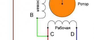
This switching occurs in the reverse device, so the rotor brushes are connected to the stator windings through it. This device may have a diagram showing which wires are connected internally.
Black wires lead to the rotor brushes (let the 5th contact be the first brush, and let the 6th contact be the second brush), gray. to the end of the first stator winding
(let there be the 4th contact) and the beginning of the second (let there be the 7th contact).
When the switch is in the position shown in the photo, the end of the first stator winding with the first rotor brush (4th with 5th), and the beginning of the second stator winding with the second rotor brush (7th with 6th) are closed.
When switching the reverse to the second position, the 4th is connected to the 6th, and the 7th to the 5th.
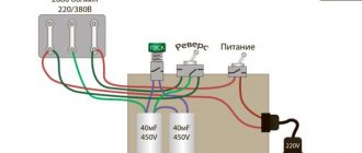
The design of the electric drill speed controller provides for connecting a capacitor and connecting both wires coming from the outlet to the controller. The diagram in the figure below, for better understanding, is slightly simplified: there is no reverse device, the stator windings to which the wires from the regulator are connected are not yet shown (see diagrams above).
In the case of the described electric drill, only two lower contacts are used: the far left and the far right. There is no capacitor, and the second wire of the power cord is connected directly to the stator winding.
Gearbox
. The drill gearbox is designed to reduce drill speed and increase torque. A gear reducer with one gear is more common. There are drills with several gears, for example two, and the mechanism itself is somewhat reminiscent of a car gearbox.
Impact action of the drill
. Some drills have an impact mode for making holes in concrete walls. To do this, place a wavy washer on the side of the large gear, and the same washer opposite.
When drilling with the impact mode turned on, when the drill rests, for example, on a concrete wall, the wavy washers come into contact and, due to their waviness, imitate impacts. The washers wear out over time and require replacement.
Source: https://ctln.ru/kak-rabotaet-revers-na-dreli/
Connecting a button
Despite the complexity of the process of replacing the button, you can do it yourself. It is important to follow certain rules. For example, you must remember that careless opening of the case often results in some parts falling out. If this is not avoided, assembling the device will be quite difficult.
To open the drill, you need to very smoothly lift the lid, and then mark the locations of the various elements of the device on paper. Repairing the button is carried out as follows:
- First you need to pick up the casing clamps and tighten them.
- Each terminal that has carbon deposits or rust must be cleaned. For this purpose, use sandpaper or alcohol.
- After this, it is necessary to reassemble the tool so that all elements of the device remain in place. Then you need to check the functionality of the drill.
- Often the cause of breakdown is abrasion of the working surface under the rheostat. It’s better not to deal with it - it’s easier to buy a new one. This detail is highly complex.
Many owners of electric drills with reverse are interested in where they can find such a circuit. First of all, you should look for it in the instructions for the tool. However, if such data is not available, you will have to ask a professional for advice or download a manual on the Internet. Instructions for many drills are available on the manufacturer's website.
How to determine whether a button is working?
To do this, you will need a regular multimeter (tester) and a screwdriver.
The diagnostic process itself is carried out as follows (using the example of the common drill model DWT SBM-500):
- Remove the drill housing cover by unscrewing several fastening bolts;
- Unscrew the two screws on the power cord clamp;
- We remove the start button block, disconnect the reverse switch (it is usually attached to clips that just need to be slightly bent). The reverse itself is sold separately and can also be replaced if necessary;
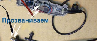
- Take a multimeter and set the switch to the beep position. We close the contacts of the tester to make sure that it is working (the device should beep);
- We call the button. To do this, we place one contact of the tester in position 2 (it should be in contact with the wire), and place the second contact on the screw that presses the 220 volt wire. When you press the button all the way, the device should emit a beep. If this does not happen, the button does not work.
How to replace a button?
To do this, you will need a flat-head screwdriver and a regular pin or thin awl.
- The button replacement process itself is carried out in the following sequence (using the example of the DWT SBM-500 drill):
- Unscrew the two screws holding the power cord in place and remove it;
- We insert the awl into the hole in the wire coming from the stator, and remove the wire along with the awl.
- We carry out a similar manipulation to remove the second wire. If you are afraid of mixing up the wires when connecting a new button, we recommend drawing a schematic diagram for connecting the drill power button;
- We take a new button and connect the power cord wires to it in accordance with the drawn diagram. Then we connect the drill itself to the button block. The wires from the stator are simply inserted into the holes until they stop;
- We attach a reverse button to the block;
- We install the block into the seat in the drill body, carefully lay the wires, and press the power cord with two screws;
- We close the cover of the drill housing and conduct a test.