You will learn how to use an indicator screwdriver, the rules for its standard use and how to use it in various ways from this article.
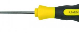
A regular indicator screwdriver is an insulated transparent handle through which a rod with a screwdriver blade at the end is passed.
There is a resistance resistor in the handle body that reduces the current strength to a minimum value that is safe for humans.
It is directly followed by an indicator lamp, a conductive pressure spring and a contact plate.
The principle of operation of the simplest indicator screwdriver is the passage of current through the tip and the indication element, followed by its exit through the body of the master, which is grounded.
In this case, a person closes the circuit with his finger, due to which the light bulb lights up.
This screwdriver is designed as simply as possible, but its scope of application is limited.
With such a tool you can only determine phase and zero, and even then the latter - by the method of elimination.
Options with built-in batteries have wider functionality.
They allow you to determine the presence of current in a conductor without touching it with a tip.
A screwdriver detector with a built-in battery is also suitable for searching for hidden electrical wiring.
What kind of lighting do you prefer?
Built-in Chandelier
As you know, a conductor under voltage emits an electromagnetic field.
It is this field that the detector detects, but the accuracy of the search leaves much to be desired.
Expert opinion
It-Technology, Electrical power and electronics specialist
Ask questions to the “Specialist for modernization of energy generation systems”
Indicator probe, multimeter, control. We study electrical measuring instruments. • If, after touching the wires, the device shows the appearance of voltage on the line, then the problem really lies in the wires that require replacement. Ask, I'm in touch!
For home network
A distinctive feature of the household network and the devices connected to it is the supply voltage of 220V. Therefore, all spare parts for testing should be selected based on this value.
For spare parts you will need:
- two wires - if you need the control for one-time use, you can also use aluminum wires. If you plan to use it repeatedly, it is better to take stranded copper wire, as it is not afraid of kinks and is more convenient to use.
- light bulb socket - choose only closed models made of insulating material; there should not be any exposed current-carrying elements to which access would be open.
- control light - selected according to the size of the socket base, and if there is a protective casing, according to the dimensions of the cap.
- Probes are not a mandatory element of the control lamp, but they greatly simplify the work, and if there are stops, they also increase safety. As a probe, you can install not only factory products, but also any available means - bolts with screwed nuts, knitting needles, etc.
- a cap or protective casing is also not a mandatory element, but reduces the likelihood of damage to particularly fragile parts. The design can be solid or lattice.
The last two points are relevant for reusable testing; if you want to test the electrical circuits once, you can assemble the tester without probes and a casing.
Production of control for 220V
To assemble the control, you will need the following tools: a screwdriver, a soldering iron, wire cutters or pliers. Depending on the situation, you may only need some of these tools. For example, if soldering is not expected, you can do without a soldering iron. It should be noted that the wires can be soldered to the cartridge rather than screwed, this will make it more reliable.
The manufacturing process consists of the following stages:
- Disassemble the cartridge into its component elements to gain access to the connection points;
- Connect the wires to the terminals of the cartridge, to do this, insert them into the terminal clamp and clamp them tightly with a screwdriver, and if such a connection is not possible, solder the wires to the terminals;
- Assemble the cartridge, lead the control wires into a hole specially designed for this;
- Connect or solder the probes to the wire terminals, insulate the connection or soldering points, the probes themselves must have sufficient insulation to prevent the possibility of touching exposed live parts during work;
- Screw the lamp into the socket and, if necessary, cover it with a protective cover.
Rice.
1: Ready test for 220V The test for 220 V is ready for use for testing wires and electrical circuits. When constantly operating such a control, do not forget to periodically check its functionality in a known-good network that is energized.
Transistor circuit
For most designs, a generator is used that produces a frequency of 50-56 Hz. It is not recommended to exceed this value.
It depends on the characteristics of the parts used:
- transistors;
- RC or LC filter;
- matching transformer, if provided;
- microcircuits.
The generator produces alternating voltage and controls (switches) power switches from pairs of field-effect transistors. They are connected to a special step-up transformer. When 12 V is supplied to the device, the transistors will begin to swing. An alternating component will appear at the outputs, which will be increased by a transformer to 220-260 V.
The power of the device depends on the number of transistors. It is not recommended to achieve 300 watts of output with only one pair. For normal operation you will need radiators and cooling. It is better to use at least 4 transistors.
Such an inverter does not require adjustment and starts working immediately. Without load, the no-load current does not exceed 300 mA. It is recommended to install transistors through mica (or other) gaskets on radiators. If the device is made on a printed circuit board, then the tracks must be made thick.
Review of a good inverter from 12 volts to 220 volts with a power of 2000 watts. If you have been choosing an inverter for a long time, we recommend that you take a closer look at this model, POWER INVERTER 2000w.
For auto
An automobile tester, unlike a household one, performs measuring operations in DC circuits with a supply voltage of 12 V. Therefore, you cannot use a 220 V tester as an automobile probe. But the manufacturing principle will be identical, although it is very convenient to use LED controls instead of light bulbs to diagnose a car.
Due to the technical features of the car's electrical wiring, testing at 12 V, performed according to the principle described above, does not provide complete information about the state of affairs in the circuit. Because of this, auto electrician control can be equipped with the following functional additions:
Rice. 2: modernized auto control
Such a circuit, in addition to monitoring the state of the circuits, allows you to determine the plus or minus at the terminals and the signal intensity. Thanks to the multi-polarity of the LEDs, one of them will light up when touching the positive terminal, and the second will signal when contacting the negative terminal.
To implement such autotest control you will need:
- Connecting wires are selected according to your needs, but professional auto electricians recommend making the length at least 2 m, since the probe has to be installed in hard-to-reach places;
- The probes can be plugs or alligators; for one-time use, you can simply strip the edges of the wires from insulation and do without probes;
- The socket for the light bulb and the light bulb itself are 12V , if the lighting device has a different connection principle, a socket of the appropriate type is installed or the wires are soldered to the terminals of the lamp (LED);
- Button – designed for switching in the control circuit, selected according to the value of the switched current;
- Two LEDs - in this example, multi-colored models are used (red for signaling the positive terminal and blue for the negative);
- Housing – designed to accommodate all the parts and install indicator lights in a visible place; a marker, felt-tip pen or plastic tube of glue can be used as a housing.
The choice of auxiliary elements is limited only by your imagination and the available tools that you find in your garage, apartment or workshop. If you are making a car tester for a specific purpose, you can exclude certain elements from the circuit, thereby greatly simplifying the device. Thus, the simplest control is considered to be a model with one light bulb or low-voltage LED.
The simplest 12V control to indicate the circuit
To make such a device, you will need a disposable syringe, a 12 V light bulb (you can replace it with an LED), wire, rubber band, utility knife, and pliers.
The manufacturing process consists of the following stages:
- disassemble the needle from the syringe and thread it into the plastic base so that one end is completely immersed inside the syringe - it should act as a contact for the light bulb.
Rice. 3: needle position in plastic base - measure the length of the wire so that it is convenient for you to wrap it around the base. Strip this area of insulation, wrap it around the lamp and tighten it with pliers. This procedure can be replaced by soldering to ensure more reliable contact.
- If the lamp base moves freely inside the syringe, put a rubber band on top of it to seal it. Insert the lamp so that the unused contact makes contact with the needle.
Rice. 4: Insert the light bulb into the syringe - Cut the plunger from the syringe so that it covers the lamp flush with the body. Make a hole in the piston for the wire, otherwise production may be very difficult.
Detailed analysis
The circuit contains a stabilizer that powers the A1 chip. It consists of a chain: R3-VD1-C3, while any similar device with a stabilization indicator of 8-10 volts can be used as a zener diode (VD1).
Please note that capacitors C4 and C5 are installed in parallel. If you do not find them with the same capacity as shown in the diagram, then you can replace them with similar ones (preferably imported) with a capacity of 4700 uF. Capacitor C6 is an element that suppresses high-frequency pulses at the output
It is best to use the K 73-17 brand of domestic production or a similar foreign version for this purpose
Capacitor C6 is an element that suppresses high-frequency pulses at the output. It is best to use the K 73-17 brand of domestic production or a similar foreign one for this purpose.
And one last recommendation or nuance. Since a 12-volt network with a consumption of 400 W will generate a current of 40 A, it will be necessary to calculate the cross-section of the wires used. This is especially true for the cable connecting the battery and the converter. Please note that the wire length should be kept to a minimum.
As you can see, making a converter from 12 volts to 220V with your own hands is not very difficult. The circuit is simple, it minimizes the number of parts, which reduces the cost of the device as a whole. Plus its work is more efficient.
Advanced do-it-yourself auto electrician inspection
Hi all! I’ve been on the resource for a long time and finally got around to registering and posting something useful.
I want to show how you can do a car test yourself, aka a tester, aka a sampler, aka a dialer) Initially I shot the material in video format, but since the rating doesn’t allow it, I’ll leave the link in the comments. Perhaps this will be more informative for someone.
Many of you probably know that testing is the main tool of an auto electrician. I have quite a lot of them, some I made myself, some I bought. A household must have a control option with a battery. It makes it easier to find the right circuits; dialing; checking for voltage; whole wire or broken. Today I will show you how to make a version with a battery.
To make the control you will need the following elements:
A compartment for 2 AA batteries, with a switch that will act as a housing;
Crocodile, for mass contact;
Non-latching button to turn on the load;
12 V light bulbs, two pieces;
3.7 V battery;
LEDs, in my case white and purple;
Resistors were selected based on the brightness of the LEDs (1 kOhm and 750 Ohms) and the volume of the buzzer (91 Ohms);
3 V piezo tweeter, with built-in generator;
A piece of wire for a crocodile - about 2 m.
Let's start placing the elements inside the case. First, let's remove unnecessary elements from it in order to place the necessary ones. I drill a hole in the body and secure the needle in it. I soldered a pad to the needle, which rests against the body, and screwed it on the other side with a screw using a contact group. The needle is metal, so it needs to be tinned. I use phosphoric acid for this. I drilled holes for the buzzer next to the needle so that the sound would come out. There will be a battery next to the buzzer.
On the back side of the compartment I drilled holes for light bulbs and LEDs. It didn’t turn out quite smoothly, but it doesn’t matter)
Now we need to solder all our components. We will solder the control elements according to the diagram.
We place the LEDs in parallel and opposite directions.
Why do you need a switch? If you connect the probe and alligator clip to the power supply and turn on the control, the battery will charge. The second reason is that often, when leaving, the probe shorted with the crocodile and the control unit was discharged. The switch will help protect yourself from such an unpleasant situation.
The buzzer helps to remotely understand that the circuit is closed.
Light bulbs and a button are needed in order to create a load on the desired wire. With their help, we can determine the power “plus”. They also help you find the central locking control wires. One light bulb consumes approximately 50 mA, and to operate the central lock, more voltage is needed. So I was forced to use 2 light bulbs.
After all the elements have been soldered, you need to fill them with hot glue so that nothing dangles. Before fixing, be sure to check the functionality of the control and whether the lid with the components inside closes.
The only thing is that I left the battery unfilled, so that if something happens, it can be changed. My placement of elements in the case is not a panacea. Everyone can modify the location to suit themselves. Inspecting an auto electrician with your own hands is quite simple, so everyone can repeat the process at home!
If the post is interesting, I can share other developments in the field of auto electrics)
Other connection examples, or how to fix them
Another, no less incorrect connection of 12V LEDs can be observed in more complex and powerful devices. With an increase in the number of diodes, manufacturers still continue to rely on battery resistance by simply connecting the elements in series. The most common reason when such devices and crafts are sent in for repair is that a single LED or their entire bunch has burnt out.
You can try to complete the diagram in several ways:
- Connecting one resistor. Such a connection will also not bring the expected result. The thing is that even semiconductor devices produced in the same batch have very noticeable differences. The point is not even that there may be a noticeable difference in the brightness of the LEDs. Here we will talk about such a parameter as voltage drop. Each device is characterized by its own current. The LED with the highest rating will most likely burn out when its current exceeds its rated current. After this, the remaining LEDs powered by 12V will not last long. Then the LED with the next highest current rating will burn out, followed by the remaining one.
- One resistor for each LED. Such a connection of a 12 volt zener diode does not conflict with the rules of circuit design. The currents become independent, but the obvious disadvantage of such a chain is its bulkiness and inappropriate load of elements.
- Chains of series-connected LEDs. Only this option for connecting devices will make it possible to simultaneously achieve maximum compactness with high performance. The only thing worth considering is increasing the supply voltage.
The parameters of LEDs also depend on their color, which must be taken into account when thinking about connecting devices to 12V.
The coolest do-it-yourself auto electrician inspection!
Everyone knows that a tester (probe) is the most, or almost the most important tool of an auto electrician; it allows you to quickly check the voltage in important parts of the wiring, “go through the fuses.” Yes, there is a multimeter for this, but try checking fifty fuses in a fuse box with a multimeter, it's long and tedious.
I have several multimeters, current clamps, an oscilloscope, all sorts of scanners, and all this is used every day, but monitoring is very necessary when carrying out initial diagnostics and checking fuses. Over more than ten years of working as an auto electrician, I made a lot of controls, these were options with a resistor, an LED and an awl made from rods from Chinese locks. The disadvantage of such monitoring is that it is impossible to determine what voltage we are measuring; the LED glows equally cheerfully from both 12 volts and 8, because of this, you can reach a dead end when troubleshooting without seeing an obvious voltage drop. I went through this, as a result, the search for a simple malfunction lasted for several hours, after which the LED controls left my work.
Varieties
There are two types of controls: for home and car. They differ significantly from each other; for a home you can use 220 Volts, while for a car you can only use a 12 Volt control. They are assembled in a similar way, the only difference is the light source that is used. Let's figure out how to make a control with your own hands, and what we need for this. Also read: automatic cabinet lighting
Advanced do-it-yourself auto electrician inspection
Hi all! I’ve been on the resource for a long time and finally got around to registering and posting something useful.
I want to show how you can do a car test yourself, aka a tester, aka a sampler, aka a dialer) Initially I shot the material in video format, but since the rating doesn’t allow it, I’ll leave the link in the comments. Perhaps this will be more informative for someone.
Many of you probably know that testing is the main tool of an auto electrician. I have quite a lot of them, some I made myself, some I bought. A household must have a control option with a battery. It makes it easier to find the right circuits; dialing; checking for voltage; whole wire or broken. Today I will show you how to make a version with a battery.
To make the control you will need the following elements:
A compartment for 2 AA batteries, with a switch that will act as a housing;
Crocodile, for mass contact;
Non-latching button to turn on the load;
12 V light bulbs, two pieces;
3.7 V battery;
LEDs, in my case white and purple;
Resistors were selected based on the brightness of the LEDs (1 kOhm and 750 Ohms) and the volume of the buzzer (91 Ohms);
3 V piezo tweeter, with built-in generator;
A piece of wire for a crocodile - about 2 m.
Let's start placing the elements inside the case. First, let's remove unnecessary elements from it in order to place the necessary ones. I drill a hole in the body and secure the needle in it. I soldered a pad to the needle, which rests against the body, and screwed it on the other side with a screw using a contact group. The needle is metal, so it needs to be tinned. I use phosphoric acid for this. I drilled holes for the buzzer next to the needle so that the sound would come out. There will be a battery next to the buzzer.
On the back side of the compartment I drilled holes for light bulbs and LEDs. It didn’t turn out quite smoothly, but it doesn’t matter)
Now we need to solder all our components. We will solder the control elements according to the diagram.
We place the LEDs in parallel and opposite directions.
Why do you need a switch? If you connect the probe and alligator clip to the power supply and turn on the control, the battery will charge. The second reason is that often, when leaving, the probe shorted with the crocodile and the control unit was discharged. The switch will help protect yourself from such an unpleasant situation.
The buzzer helps to remotely understand that the circuit is closed.
Light bulbs and a button are needed in order to create a load on the desired wire. With their help, we can determine the power “plus”. They also help you find the central locking control wires. One light bulb consumes approximately 50 mA, and to operate the central lock, more voltage is needed. So I was forced to use 2 light bulbs.
After all the elements have been soldered, you need to fill them with hot glue so that nothing dangles. Before fixing, be sure to check the functionality of the control and whether the lid with the components inside closes.
The only thing is that I left the battery unfilled, so that if something happens, it can be changed. My placement of elements in the case is not a panacea. Everyone can modify the location to suit themselves. Inspecting an auto electrician with your own hands is quite simple, so everyone can repeat the process at home!
If the post is interesting, I can share other developments in the field of auto electrics)
Connecting LEDs to a high-frequency power supply
Auto electrics is not a difficult matter at all, you just need to understand a little about electricity and be able to recognize faults. They must be eliminated in time so that the car can move unhindered.
A common problem with a car's electrical system is faulty fuses. If the fuse fails, it must be replaced with a new one. The duplicate must be exactly the same denomination as the new one.
You can also fix some other simple breakdowns yourself. If you cannot cope with more complex problems, then it will be easier to seek help from the nearest auto repair shop, where specialists will diagnose and identify all breakdowns. Afterwards they will make a quality repair.
If there is a burning smell in the car interior, it means that there is a short circuit or fire in the electrical wiring. You cannot move in this state; you must stop and open the hood. After this, disconnect the terminals from the battery and call a tow truck, which will take you to a car service center.
Expert opinion
Strebizh Viktor Fedorovich, leading construction foreman
To make it convenient to use the test, it is recommended to additionally connect the ends of each wire with probes, which will be much easier to use if you need to check the voltage in the outlet. If you need an explanation of unclear points, write to me!
Features of the probe and its operating principle
The continuity probe is structurally a plastic capsule, inside of which a resistor with a high resistance is placed. A metal rod extends from the plastic base, the end of which is used for direct contact with the contacts of electrical equipment. The device shows the presence of voltage; green and red LED lights located on the plastic case act as indicators. The green LED indicates low circuit resistance, the red LED indicates the presence of voltage.
A car test probe, which is essentially a voltmeter, is indispensable when identifying faults in a car's electrical equipment, as well as when installing new electrical equipment on a vehicle.
The diagnostic device makes it possible to determine the integrity of an electrical circuit or a separate section of it, identify locations of broken connections, unreliable contacts, the location of failed parts, as well as identify a number of other damages. To carry out a quick check of current-carrying equipment, the use of a continuity probe is the most rational and expedient solution.
Car probe 6-24V 110mm “needle” brass AVTODELO
Automotive probe for checking the ignition spark JTC
Automotive probe for checking the ignition spark TEST-M
Car probe for checking the ignition spark 0.5m FORSAGE
Automotive probe 6-24V ROCKFORCE
Automotive probe 6-24V FORSAGE
Car probe 6-24V 120mm “needle” TECHNICIAN
Automotive probe 6-24V 120mm plastic case SPARTA
Automotive probe for checking the ignition spark FORSAGE
Automotive probe 6-24V FORSAGE
The use of a continuity probe for testing various types of electrical equipment
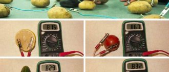
Battery check
Using a probe, you can check the presence of voltage at the battery terminals. To do this, using an alligator clip, you need to connect to the battery terminal with the “-” sign, and attach the end of the probe to the terminal with the “+” sign.
Checking the fuse
To check the fuse, touch one end of its terminal to the positive terminal of the battery, and the end of the probe to its second terminal.
Checking the incandescent lamp
To check an incandescent lamp with a continuity probe, place one terminal of its base to the positive terminal of the battery, and attach the end of the probe to the second. When testing a light bulb with two filaments (such as a car headlight bulb), test them one at a time.
How to use a screwdriver indicator
Well, we looked at three types of indicator screwdrivers, now we’ll look at how to use an indicator screwdriver and test them in operation.
Regular indicator
The pointer of this indicator screwdriver is equipped with two working areas. The first one looks like a flat-head screwdriver - it comes into contact with electrical wiring elements that are energized. The second provides sufficient resistance and is located on the handle of the screwdriver. It also has a two-pole switch.
Let's consider an example in which a phase wire is connected to the first contact, and a neutral wire is connected to the second. The voltage indicator determines which wire the phase is going through.
To determine, it is enough to hold the contact on the handle of the voltage indicator with your thumb, and then bring the working area of the indicator alternately to both contacts of the circuit breaker. In this case, you need to make sure that your thumb remains bare - you should not wear gloves when using the device.
How to use an LED indicator screwdriver
As mentioned above, these indicators are distinguished by the presence of a function not only for contact, but also for non-contact use in the presence of a light warning.
If you are using the classic contact method and you need to find out where the phase is, it is enough to bring the working part closer to both contacts of the circuit breaker. When you bring the device to the zero contact, you will not notice any changes. When you check the phase one, the signal light will immediately light up, which will allow you to immediately find out that there is voltage at this contact.
Checking a car relay
In addition to the electromagnet winding, an automobile relay also has contacts that, over a long period of operation, can burn out and, as a result, stop switching electrical circuits. Using a continuity probe, you can check both the integrity of the electromagnetic winding and the serviceability of the contacts.
To check the relay winding, you need to attach one of its terminals 85 or 86 to the battery terminal with the “+” sign, and attach the end of the probe to the second terminal. The serviceability of the contacts is determined by touching the terminal of the moving contact 30 to the terminal, and by touching the terminal 87a with a continuity probe.
In the same way, any microswitches and switches are checked.