ASU – Input distribution device
ASU - input-accounting-distribution devices are designed to receive, meter and distribute electrical energy and protect lines during overloads and short circuits.
ASUs are used in industrial enterprises, data processing centers (DPCs), as well as in electrical installations of residential and public buildings.
ASUs are divided into: single-panel, multi-panel, cabinet.
The main purpose of the ASU is to supply buildings or individual parts of premises with electricity.
Preparing the device for operation
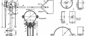
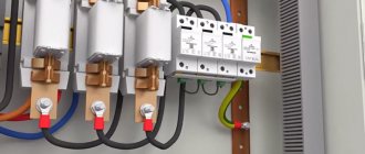
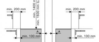
Before installation, the input distribution device must be placed strictly horizontally on the floor. When using the top cover for cable entry, install glands of the appropriate size (corresponding to the outer diameter of the wire sheath). To install them, holes are drilled in the housing cover. After entering the cables into the device, they should be separated and secured inside the cabinet using special brackets with perforations. Neutral conductors are mounted to the N bus (insulated), and the protection conductors are mounted to the PE bus (electrically connected to the housing).
Technical characteristics of the ASU
| Type of main circuits | with solidly grounded neutral |
| Rated voltage of main circuits | 220, 380 V (AC) |
| Rated voltage of control circuits | 24, 48, 110, 220, 380 V (DC or AC) |
| Rated voltage of additional auxiliary circuits | any, not higher than 380 V |
| Rated insulation voltage of main circuits | up to 1000 V |
| Maximum rated input current | up to 630 A |
| Maximum value of expected short-circuit current | up to 50 kA |
| Rated AC frequency | 50 Hz |
| Type of grounding system | TN-S, TN-C, TN-CS |
| Dimensions (for single shell): | height with plinth up to 2200 mm; width up to 1200 mm; depth up to 800 mm; |
| Type of supporting structure | frame made of prefabricated metal or welded structure |
| Structural layout | row, corner, cabinet |
| Internal sectioning (according to IEC439-1) | up to 3b |
| Type of external coverings | external elements – finely structured polyester (fine shagreen) powder enamel (default RAL 7035); internal elements: zinc coating. |
Characteristics of ASU panels
The devices reliably protect all devices connected to the electrical network. The range includes ASU panels for single-phase (220 V) and three-phase (380 V) power systems. All elements are protected from voltage surges, short circuits and leaks.
ABB-electroshield specialists will help you select an ASU panel and provide consultations on the specifics of choosing certain systems. To order equipment, just contact the managers, leaving your contact information to order a call back.
Working conditions of the ASU
| Height above sea level | up to 2000 m |
| Temperature range (standard) | from -5°С to +40°С |
| Relative humidity (at 25°C) | up to 85% |
| Type of external environment | non-explosive, the content of corrosive agents corresponds to atmosphere type II or III according to GOST 15150 |
| Safety and reliability | |
| Degree of protection of the cabinet outer shell (standard versions) | IP31, IP41, IP43, IP54 |
| Resistance to mechanical factors | M4 |
| Standard climate versions | UHL3 or T3 |
| Seismic resistance | up to 6 points (with installation height up to 20m.) |
| NKU service life | 30 years |
Input distribution board. Main types
There are many differences in the input distribution board. Differences in the degree of protection, in the type of housing, in the installation method, in the maintenance option, as well as in the installation location, the input switchboard can be divided into: ASU1, ASU2 and ASU3.
- The complete set of ARU1 switchboard is installed in basements and on staircase landings;
- Place of installation of ASU2 in switchboard rooms. As a rule, such a cabinet is filled with a professional set of components.
- The VRUZ switchboard consists of a minimum set of electrical appliances and is an integral part of the main switchboard.
Order ASU
You can get the cost of the ASU in the following ways:
send an application with a completed questionnaire or a one-line diagram to us by mail
Contact us by phone: +7 (495) 225-99-15
109428, Moscow, Ryazansky prospect, 10с18, office. 6.3A. 143985, Moscow region, Balashikha, Savvino microdistrict, Promyshlennaya street, 49A.
Send a request and we will contact you Leave a request Request a call
ASU cabinets manufactured by ELSIN are installed at the entrance to the building and have a metal casing.
Prices for ASU
The price of an ASU depends not only on the number of machines and panels, but also on the complexity of assembly and the manufacturer of the automation. Below I want to provide you with several options for calculating the cost of an ASU; this is exactly the commercial offer you will receive from us by sending a request to our general email.
Please note that before taking a price from the Internet for an ASU, you first need to send it to us for calculation. We will give a clear price, price and quality guarantee.
| Object: ASU at 250a | Unit change | Qty |
| Introductory panel | PC. | 1 |
| Housing 2000x600x450mm | PC. | 1 |
| Side wall | PC. | 2 |
| Perforated panel | PC. | 1 |
| Switch-disconnector VR32I-35V71250 250A | PC. | 1 |
| Fuse holder DP-35 size 1 250A | PC. | 3 |
| Fuse insert PPNI-35 160A size 1 | PC. | 3 |
| Current transformer TTI-30 150/5A 5VA without busbar, accuracy class 0.5 | PC. | 6 |
| Test box | PC. | 1 |
| 230ART-03 RN 5-7.5A; 3*230/400V (c.t. 0.5S/1.0; RS-485; LCD) | PC. | 1 |
| Ammeter E47 150/5A 72x72 AC connection via a transformer (accuracy class 1.5) | PC. | 3 |
| Voltmeter 500V 72x72 AC direct connection E47 | PC. | 1 |
| Cam switch PKP10-44/O 10АUc-O-Ua-Ub4Р/ | PC. | 1 |
| Capacitor K-73-28-1-1000V-0.47uF | PC. | 3 |
| Single-pole automatic switch 6A C VA47-29 4.5kA | PC. | 1 |
| Fluorescent lamp LPO-6w electronic ballast with lamp G5 LPO2001 | PC. | 1 |
| Kit of mounting parts | PC. | 1 |
| Total including VAT: | from 30 000 | |
| Estimated production time | 2 days | |
| Object: ASU at 400a | Unit change | Qty |
| Introductory panel | PC. | 1 |
| Housing 2000x600x450mm | PC. | 1 |
| Side wall | PC. | 2 |
| Perforated panel | PC. | 1 |
| Switch-disconnector VR32I-37V71250 400A | PC. | 1 |
| Fuse holder DP-37 size 2 400A | PC. | 3 |
| Fuse insert PPNI-37 200A size 2 | PC. | 3 |
| Current transformer TTI-30 150/5A 5VA without busbar, accuracy class 0.5 | PC. | 6 |
| Test box | PC. | 1 |
| 230ART-03 RN 5-7.5A; 3*230/400V (c.t. 0.5S/1.0; RS-485; LCD) | PC. | 1 |
| Ammeter E47 150/5A 72x72 AC connection via a transformer (accuracy class 1.5) | PC. | 3 |
| Voltmeter 500V 72x72 AC direct connection E47 | PC. | 1 |
| Switch cam. PKP10-44/O 10АUc-O-Ua-Ub4Р/ | PC. | 1 |
| Capacitor K-73-28-1-1000V-0.47uF | PC. | 3 |
| Single-pole automatic switch 6A C VA47-29 4.5kA | PC. | 1 |
| Fluorescent lamp LPO-6w electronic ballast with lamp G5 LPO2001 | PC. | 1 |
| Kit of mounting parts | PC. | 1 |
| Total including VAT: | from 35 000 | |
| Estimated production time | 2 days | |
| Object: ASU at 630A | Unit change | Qty |
| Introductory panel | PC. | 1 |
| Housing 2000x600x450mm | PC. | 1 |
| Side wall | PC. | 2 |
| Perforated panel | PC. | 1 |
| Switch-disconnector VR32I-39B71250 630A | PC. | 1 |
| Fuse holder DP-39 size 3 630A | PC. | 3 |
| Fuse insert PPNI-39 315A size 3 | PC. | 3 |
| Current transformer TTI-40 300/5A 5VA without busbar, accuracy class 0.5 | PC. | 6 |
| Test box | PC. | 1 |
| 230ART-03 RN 5-7.5A; 3*230/400V (c.t. 0.5S/1.0; RS-485; LCD) | PC. | 1 |
| Ammeter E47 300/5A 72x72 AC connection via a transformer (accuracy class 1.5) | PC. | 3 |
| Voltmeter 500V 72x72 AC direct connection E47 | PC. | 1 |
| Cam switch PKP10-44/O 10АUc-O-Ua-Ub4Р/ | PC. | 1 |
| Capacitor K-73-28-1-1000V-0.47uF | PC. | 3 |
| Single-pole automatic switch 6A C VA47-29 4.5kA | PC. | 1 |
| Fluorescent lamp LPO-6w electronic ballast with lamp G5 LPO2001 | PC. | 1 |
| Kit of mounting parts | PC. | 1 |
| Total including VAT: | from 40 000 | |
| Estimated production time | 2 days | |
Scope of products
ASU panels are used as independent electrical installations in office, retail, industrial and warehouse premises.
When distributing electricity in an industrial enterprise, equipment of this type is one of the main elements of the power supply system. In this case, the switching devices are electrically connected to automatic transfer switching devices (ATS), lighting panels and other electrical equipment.
The assembly of ASU cabinets is carried out at the enterprise in the assembly shop of the ELSIN company. A professional installation team installs switching and protection devices, automation and control equipment, wiring and connecting wires of switching devices.
The quality of installed products and the timing of installation work are under constant control.
CS-CS.Net: Laboratory of the Electroshaman
An example of the diagram and layout of an ASU panel for a country house
I warn you : I am somewhat unfamiliar with the deep technical aspects of this topic, because I have rarely encountered it (and am now delving into it), and the post will relate more to the view from the words of the installer. Therefore, please do not be shy and point out errors and inaccuracies in the comments. I need this post in order to stop explaining the same thing to customers about underground input, grounding systems and to remove a bunch of superficial questions that I’m tired of writing out long sheets of text on.
Questions on the topic of input arise most often in any dacha construction, and usually end with all sorts of “But I was allocated 15 kW three phases.” After this, the person thinks that he has said enough, and immediately expects from me a quick and hellish miscalculation of the shield. And if in the case of an ordinary apartment this immediately means three phases, zero and PE, a meter in the floor panel and an input machine with a nominal value of 25A, then in the case of country house construction these words usually begin a long correspondence and detailed questions about the input.
In dacha construction, it turns out that electricity can be supplied to a house in different ways and according to different technical conditions. And it’s all of them that I want to briefly review and give some simple recommendations like “If this is the case for you, do this; if it’s not like this, do this” (damn - and I just aired another soap on the same topic).
There will be few pictures, but a lot of text. I'm excited =)
So, in the case of electricians in country houses, the following series of questions arise that need to be clarified and resolved:
- What kind of grounding system can be made in a particular case. This depends on the condition of the main supply line, the transformer substation and the requirements for the ASU and metering unit;
- What should be the metering unit in the ASU and where should it be located: on a pole or in the house, what needs to be sealed (meter, input machine, switch);
- What type of input to the house to use. Typically this is either overhead or underground. In the case of air input, you also need to think about lightning protection (install an SPD).
Moreover, all these issues are interconnected: if there is an air input, and the metering unit is on a pole, then it may not be possible to make a TN-CS grounding system, which is more preferable.
Ground loop
First we talk about the most difficult thing - grounding systems . Our task is to provide ourselves with a PE protective conductor, because in modern networks you can’t live without it. If in multi-apartment residential buildings they have already taken care of us and provided it to us in its pure form or left the opportunity to separate it from the zero riser (under certain conditions, which I wrote about in the post about the input and the floor panel), then in this case we have to do everything ourselves from scratch.
The general meaning is as follows: first of all, we provide ourselves with natural and real grounding . In its original essence: we stick something conductive into the soil (a lot of pieces of iron) and make a wire from it into the house. And under certain conditions that we must strive , we re-ground the zero that comes to us at the input. Accordingly, re-grounding of the zero must be done at the input, before all metering nodes and switching devices, and this is precisely what is affected by the requirements for the metering node.
So, grounding . There are a lot of pictures, videos and the common phrase on the Internet: “hammer three corners into the ground, scald and remove the steel strip.” But we will try to understand in detail, to get to the bottom of the meaning of these actions in order to understand what is being done and be able to solve the problem in different ways under different conditions.
First, you need to choose a place to organize the ground loop. It's best to find a place that stays moist, but not too wet. That is, burying it in a gutter will not work, but next to it, it is possible. The next important point, just in case, is to ensure that the grounding loop is kept at a distance from people. In the event of a serious accident, a step voltage may arise around the circuit, the magnitude of which decreases depending on the distance.
Secondly, the circuit should be made using very reliable connection methods. It is best to use welding, but bolted connections are also suitable, especially since some ready-made grounding systems use this method. Let me remind you that the grounding wire itself, which is used to connect it to the ASU, must have mechanical strength. Therefore, a steel strip or wire is used as it.
Thirdly, the grounding loop must be checked after manufacturing. There are special devices for this that are expensive. At home, the quality of the circuit can be checked like this. Take some powerful load (an electric kettle or heater will suffice) and connect it in two ways: between the input phase-zero and between the phase and the ground loop. Next, use a tester to measure the voltage at the load in both cases and, if it is more or less equal, then the circuit is good. If you get 60 volts, add more hardware.
If you are too lazy to bother with a bunch of tough men and a hammer to hammer in corners, then you can look towards modular grounding systems. Such systems consist of individual pins that are twisted together and driven into the ground to the required length, and also have a bunch of different connectors and accessories. For example. such a system from DKC: https://dkc.ru/ru/catalog/438_/ and it is in a digestible form in the ABN catalog: https://abn.ru/catalog/dkc/jupiter/ground.shtml. Typically, such systems have an attachment for a hammer drill, which allows them to easily hammer everything in the hammer mode with one person. There was even a video: https://www.youtube.com/watch?v=Ma_cm1H0WWI.
The grounding loop has been made. Next thing. GZSh - Main Grounding Bus . Globally speaking, this is the place where the ground loop in the ASU comes. Usually this is an infernal piece of hardware with bolts onto which the conductor from the circuit is screwed. I also get asked questions about how to make it better. Crap! It's just a HARDWARE. If you brought your steel strip from the ground loop into the building, nail it to the wall of the building (or panel) and weld about five bolts onto it. Here's GZSh for you. Again, there are pre-made options, from the same DKC, into which you can clamp steel wire or strip.
If there are any massive metal structures around, securely buried in the ground, then they also need to be connected to the main conductor with their own conductors. This could be some kind of steel casing pipe from a well; specially drawn wire from the foundation reinforcement in advance, if inside the foundation the reinforcement is fastened together and has an electrical contact, a metal water supply pipe, etc. But you shouldn’t connect any metal fence: it is not buried as deep as required.
Let's say we created a grounding loop, tested it and brought it to the GZSh. Now another stage of witchcraft begins.
Main line
We need to figure out the input and the supply line of the dacha network. We need to assess its reliability and condition. In theory, it should always be in good condition, but usually it is not maintained, they cannot say anything, and, like the risers of an apartment building, it has to be assessed by eye.
Let me remind you: our task is to re-ground the zero coming to us from the input. That is, put him on the GZSh. This is done in order to increase the reliability and safety of the power supply system. Imagine the situation: somewhere on part of the main line a zero has burned out. And all our loads are somehow connected between phase and zero. If in this case we do not have the zero re-grounded, we get anything we want on the voltage: the phase passes through the equipment and ends up at zero, hanging in the air. That's right: the solution is as follows. Since the low voltage zero at the transformer substation is always grounded, we will ground it again locally.
BUT! If we have a frail main line that is dying, then if the zero on it burns out, our re-grounding will become a working zero for this entire line. There are two options: either it will go for a ride and everything will be fine, if the load on the main line is small, or due to the sharply increased current along our grounding loop, its conductors will heat up and set something on fire.
Therefore, we look at the pillars. If we see on them a fresh line made with SIP4 wire (which has now become the standard for overhead lines), if they agree to allocate sufficient power (say, the input rating is 32..40A for single-phase input and 25 A or more for three-phase) - the line quite good. This is about the same as I once wrote about an apartment building: “Look into the floor panel. If you have new colored wires there, you have had the riser reconstructed.”
Additionally, for some poles, the same re-grounding of the main zero along the entire line can be performed. Depending on the design, it may look like a steel wire running down from a pole into the ground, or one of the main line wires will be attached to part of the pole's reinforcement using a special piece of iron at the top of this pole. Re-grounding the line can be done through several poles, so you have to run around. If it exists, we definitely consider the line to be good and strive to make TN-CS .
If our line is rotten, frail, and made of some kind of uninsulated aluminum, which is attached to porcelain insulators, then most likely re-grounding the zero will be a risky business, and you will have to use the TT .
Accounting unit
Step further. Accounting unit . Here we have almost no right to do anything the way it needs to be done, and we are obliged to listen to the strict recommendations of the office that will supply us with electricity. And here, too, there is a problem - the very location of the metering board and the requirements for its contents.
Now they have begun to move metering from houses to poles next to them to avoid the theft of electricity. You need to put a panel on the pole, which has an input machine and a counter, and this introduces the following problem:
- Since the re-grounding of the zero must be done before the metering unit, we have to do it right at the panel, and only if they allow us to change anything in this panel. Moreover, if the entry into the house goes further by air, then the meaning of PE is lost, and something needs to be reinvented in the house.
- In some cases, such a sign is already installed in advance (these are all sorts of villages with the advertisement “All communications have already been connected”); it has an input machine that also breaks the zero. If we have at least some kind of switching device in the neutral conductor, then we can never consider it a PEN and are forced to use the TT system.
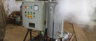
An example of such a shield is shown below:
An example of an ASU panel on a pole from a developer
Here the developer installed a switch before the meter, which is good, and an input machine after the meter. The meter has a radio modem for remote readings and remote control of allocated power. Although the input circuit breaker is rated at 32A, the power is limited to 15 kilowatts. And, most importantly, the line is new - but nothing can be done. We have no right to touch the shield, and are forced to use the TT system, which is more dangerous than TN-CS.
Here's another shield. It is already in the house, and it can be converted and converted to the TN-CS system.
An example of another ASU panel in a house
Therefore, the question of filling the shield should also be clarified before doing anything with the input of electricity. You need to get either technical specifications, or get to the bottom of a local electrician, who will tell you the permissible rating of the input circuit breaker and say that. that needs to be filled.
Ideally, you should seek to install the shield in the house, somewhere in the basement or in a service room on the ground floor of the house. A panel on the facade of the house is also a very ideal option for organizing a normal power supply system.
Here I have a question for the public: And if we have a metering panel on a pole, but the input circuit breaker there is three-pole, and the zero just passes through the meter - after this metering unit in the house, we can count this zero with a PEN, re-ground it and separate it on PE and N?
In theory, we can’t.
After we have figured out the metering unit, we figure out how to supply electricity to the house. It is clear that if the metering unit is in the house, then, of course, you need to think about input before it =)
Entering the house
There are two types of entry into the house: underground cable and overhead entry . You also need to think about them and decide which one is better and more convenient.
Underground cable allows you to get rid of unsightly wires that spoil the façade of your home. But the most important thing is that we can cross the TN-CS near the pole with the metering unit and bring a solid cable to the house directly from the PE. But underground cable is more difficult to lay and is more expensive: you only need to use armored cable type VBBShV .
I see the underground input like this (you can correct me here too). There must be either a metering unit or some kind of disconnector on the pole to remove power from the entire cable. Let it be in a box and sealed, etc. After this, the cable descends along the pole into the ground. At a height of less than 2 meters (well, or along the entire height), we additionally protect it from mechanical damage either with a steel pipe or a steel angle. Next, the cable is buried in the ground and brought to the house. In our house we either already have a main switchboard (Main Distribution Board) or a metering unit combined with it.
The air input is made with a wire of the SIP-4 brand (all of whose cores are insulated; SIP stands for Self - Bearing Isolated Wire ), and at first glance it is done as simple as shelling pears: pull the wire on special anchor clamps, connect it to the main line with special piercing clamps - and that’s it .
But in fact, such input has some features:
- Air input is less reliable than underground. Therefore, no chips like “they installed a metering unit on a pole, switched to TN-CS with PE and extended it into the house” will not work. Either only N (if the main line is weak) or PEN can come into the house, which must be re-grounded.
- The air inlet may be struck by lightning. , and best of all, in the panel on the facade of the house) it is necessary to install an SPD ( Pulse Surge Protection Device ) .
Results
If you add up all the information, you get the following:
- We find out the requirements for the metering unit. Where should it be located, how much power is provided, what to seal, how many poles of the input switch/automatic machine can be made;
- We find out the condition of the main line. Is it possible to re-ground the zero, or is the line weak?
- We make a decision about what kind of entry we will make into the house;
- In any case, we make and check the grounding loop;
- We are assembling (or are already understanding the assembled one, if we got it from the developer) metering panel / main switchboard;
- We collect all the other shields.
If the described division of zero is represented in diagrams, it turns out like this:
Example of a switchboard diagram for a TT system
In the case of a TT we have two separate zero and PE buses that are not connected to each other. In fact, we don’t need the zero bus at the input, so of all the buses, only the GZSh .
The TT system has an important feature. Since the working zero from the main line is not re-grounded, in the event of some kind of accident (zero burnout, wires snapping), ANY voltage can be at zero! Therefore, in the case of using the TT system, we are again somewhat on the money, since we are forced to install RCDs on all, all lines to increase safety. The RCD will be triggered by a leak both from phase to PE and from zero (if there is sufficient voltage for this) to PE. Via cable or through a person =)
TN-CS system is more protected from all these miracles. In this case, our “zero” from the pole is already called PEN and, in order to divide it into PE and N, we re-ground it by connecting it to the GZSh .
Example of a switchboard diagram for the TN-CS system
Then even if the PEN comes off somewhere or falls off, everything will still work for us. And if dangerous voltage appears on it, then there will be a normal phase short circuit to ground within our section of the line. In the case of the TN-CS , we may not install RCDs on some lines (for example, in dry rooms).
Pay attention to these diagrams. They are drawn in two versions specifically to show the following. In some cases, the installation of the metering panel is distorted so cunningly as to leave the opportunity to later switch from the TT to the TN-CS . For example, if we connect the PEN not directly to the GZSh, as shown in my lower figure, but to the N bus, then we will get the following:
- If we do not connect the N and GZSh buses with a jumper, we will have TT;
- And if you connect it, it will be TN-CS;
In most cases, these tires need to be sealed. And sometimes you can use distribution blocks of the BRU type or other suitable ones (for example, in 2016, DBL blocks also appeared).
I will soon have to install a metering panel according to the diagram from the title of the article, so I will add my photos here later. In the meantime, here is a beautiful description of the ASU from my colleague Marsik (El-Fi.Net): https://www.el-fi.net/2012/08/blog-post_2588.html.
PS. I can make a small review of SIP wires if necessary. I myself am interested in how it is and what. Anyone else interested?
Main technical characteristics of ELSIN equipment
To ensure reliable operation and safe operation of electrical equipment, it is necessary to purchase an input distribution device with the appropriate characteristics. The main ones are the values of the rated voltage and rated current of the input device.
Additionally, by agreement with the customer, a supplier of switching equipment and measuring instruments is selected, and the degree of protection of the housing from external factors is determined.
All switchgears are equipped with a locking mechanism.
Design features of the ASU
The assembly of input distribution devices is made from a metal case, from switching equipment (circuit breakers, circuit breakers, contactors, fuses, etc.) that provide protection of input and output power cable lines from emergency situations (short circuits, low or high voltage, overloads, etc. etc.), and power distribution systems for switching equipment (copper or aluminum buses and power wires).
If necessary, access to the protective equipment is carried out from the front by qualified personnel and depending on the design. Access to the switching equipment can be with the door open or directly on the door itself (using remote handles).
Floor panels are fastened to the floor using fasteners. The need to fasten the housings is necessary so that the panels (if not used correctly) do not move out of place or fall, which can lead to more serious consequences.
Input distribution devices are manufactured in full compliance with TU 3434-004-11457458-2015 and fully meet the requirements set out in the current edition of GOST, valid in the Russian Federation (GOST 32396-2013, GOST IEC 60439-3-2012, GOST 32397- 2013).
Advantages of working with ELSIN
The ELSIN company manufactures ASUs in Moscow, using modern high-quality materials in production. The set of accompanying documentation contains certificates, diagrams, passports for the installed equipment.
All manufactured equipment undergoes a detailed inspection by the Quality Control Department (technical control department). Strict quality control requirements guarantee the customer high reliability of the purchased equipment.
The products manufactured by the enterprise guarantee long-term reliable and safe operation.
Reactive power compensation units (RPC) are designed to improve the operation of equipment at industrial enterprises. Oscillatory processes occurring in the electromagnetic fields of electrical networks under the action of synchronous electric motors and generator power plants that produce electric current reduce the quality of the generated electricity.
Application area
The introduction of electrical equipment such as UKRM capacitor units compensates for reactive power. The equipment produced by the company works reliably in energy-intensive industries. This type of device is most widespread:
- at oil refining and gas industry enterprises;
- in steel and cement shops;
- woodworking industries;
- in mechanical engineering.
In addition, capacitor units are used in enterprises operating asynchronous motors, compressor and welding equipment, melting and electric arc furnaces.
and other manufacturers of capacitor units produce equipment that does not require operational control of its operation. The reactive power compensation process is fully automated.