How to draw a scale on a dial indicator
Hello dear readers.
In this article I want to talk about how to draw the scale we need for our measuring instruments. I will draw a scale, which in scientific terms means calibrate, for my milliohmmeter, which I wrote about earlier. You can read the article here. And so we have a head, found who knows where and when, it had been lying around for a long time. We carefully disassemble it, but before we unscrew the scale, we immediately measure the radius of the arc where the divisions are located.
See Photo 1. We measure carefully, without damaging the rotating system of the measuring head, and remember its value. If you, like me, also have a paper one on the main scale plate, then you need to carefully remove it in hot water. This is what happened, look at photo 2. Photo 3 shows a freshly drawn new scale.
So, open the FrontDesigner_3.0 program, if you don’t have it, download it and install it.
After opening the program, a window similar to this will appear in front of you (screen 1).
Right-click on active field 1 and select “properties”. We set the size of the sheet on which we will draw the scale in accordance with its dimensions. Here you can choose the color of the sheet, I chose white.
Next, click on button 2 - “Scale” and screen 2 will open in front of us, the window can be expanded to full screen.
When I hover the cursor over the active field, the latter takes the form of a magnifying glass with the name “Magnifier”; if at this time you click on the left or right mouse, the image will run away and you will have to draw it all over again. So, take note of this. Perhaps this is a glitch only in my program, but I’m already used to it. Click on button 1 and select “Circular linear scale” from the drop-down list.
Then click “parameters” (see screenshot 3) and begin filling out the required fields. 1 – select the angle by which the arrow deflects, since for all measuring heads it is approximately 90°, then we set this value.
Next, we set the radius value that we measured and remembered. “Line” - set “yes”, in this case the arc on which the divisions are located will be visible in the figure. “Center of circle” - you can also put “yes” for convenience. “1.Divisions.Segments” - The number of large divisions, I have ten of them. “Divisions. Length mm” - since my scale is large, I set it to 7mm. “Divisions” - set “Yes” - we allow ourselves to draw divisions between large divisions. Next, as with large ones, we set the number of small divisions between two large ones - 10, set the height of the small divisions - 5mm. We don’t need “rotation” - set it to “0”. “Inscriptions” - set “Yes” - these are numbers above the divisions. “High. t - mm " - height of numbers. “Gap” - I set it to 3mm - this is the distance between large divisions and inscriptions. “Text angle” - 0. Further, see the screenshot. As a result, we get the scale that you see, but without the inscriptions. Click on button 2 – “Inscriptions” and look at screen 4.
Everything is clear here; opposite the number of each large segment we enter what we need. Next, click on the green checkmark - “Add scale to layout”, the main program window opens again, but with our scale - screen 5.
My milliohmmeter has two measurement limits, so I would like to display it on this scale. To do this, click on the “Scale” icon again and draw another scale for another limit (see screenshot 6).
The peculiarity of this scale is that the divisions are located on the other side of the arc. This is achieved by placing a minus sign in front of the numerical value of the division height. And I put "no" for small divisions. Next, click on the green checkmark and combine the two scales in the main window. To facilitate further work, turn on the scale grid by clicking on the corresponding button - 1. After that, in accordance with the dimensions of our scale - photo 2, draw a rectangle. We will then cut off the part we need along the sides of this rectangle. Now we can insert the text or icon we need, you’ll figure it out for yourself. We get screen 7.
Next, click on the printer icon and print the scale. I print mostly on matte photo printer paper. Now about gluing. First, cut out the scale blank along the lines of the rectangle. Then we degrease the aluminum scale (photo 2). Apply PVA glue to both pieces. Let it dry a little, carefully combine both pieces and iron them through fluoroplastic film with an iron at a temperature of 60 degrees Celsius. Then, using a file (I usually use a round, small file all the time), we cut off the unnecessary paper. We use an awl to pierce the holes for attaching the scale, and assemble the device in the reverse order. ALL. Look at photo 4. Hurray! Clear victory.
Yes, a little more. If it is assumed that the device will work not only at home, but also on the street, then the paper scale must be protected with a layer of colorless varnish. For these purposes, I always use colorless imported car varnish in aerosol packaging - “Body Acrylic”. Good luck to everyone, goodbye. K.V.Yu.
Source: www.kondratev-v.ru
Principle of operation
Electromechanical type meters were the first to be created. They operate using the magnetoelectric principle. A permanent magnet is fixedly fixed, and a steel core is installed between its poles. This structural element is installed in such a way that a constant electromagnetic field can be formed in the annular air gap.
A frame made of aluminum is installed in the gap on the axle shafts. She is able to move freely. There is also a spool of thin wire on the frame. The indicator arrow of the device is attached to the frame using springs. As soon as an electric current begins to pass through the device, an electromagnetic field appears in the winding. The frame interacts with it and deflects along with the arrow to a distance corresponding to the voltage value.
The design of the meter also contains an induction damper - an aluminum plate mounted on a frame with an arrow. In accordance with Lenz's rule, eddy currents arising in the damper interact with the magnetic field that generated them and slow down the oscillations of the device pointer. To achieve the required measurement accuracy, the device must not be exposed to gravity during operation.
To solve this problem, the moving part of the meter is equipped with a system of weights moving on rods. In addition, to ensure accurate measurements, it is necessary to reduce the friction force of the steel tips. This is achieved through the use of special wear-resistant steels. Parts made from them are polished.
Before starting the measurement, the user needs to set the indicator arrow to the zero position.
For this purpose, the design of the device includes a special adjustment screw connected to a spring. This is a classic design, but today there are devices containing magnets of different shapes. Moreover, in some designs the magnet is movable.
We recommend reading: The simplest 220 volts without a driver (the simplest way to power an LED from a 220V network)
Voltmeter with extended scale. Measuring range calculation
This voltmeter, unlike a conventional one, allows you to accurately measure voltage in a certain specified range. For example, to monitor the voltage of a car battery, a voltmeter with a scale from 10 to 15 volts will be very convenient, since it makes it possible to monitor even minor changes in voltage in this range.
Author's note: further in the text of the article a non-standard “delta” icon will be used
Since there is no such icon on the keyboard, I will refer to it as ^U .
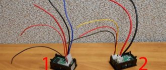
In order to make the scale “stretched”, it is enough to add a threshold element to the measuring circuit, for example a zener diode with the required stabilization voltage value. And if you add another such zener diode, connected counter-connected, this will significantly reduce the total temperature instability of the entire circuit, which is shown in the figure below:
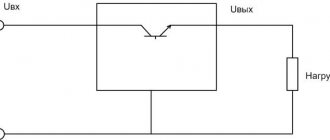
The voltage at the input of the circuit is distributed between resistor R and zener diodes VD1 VD2. If the voltage drop across the zener diodes is constant, then across the resistor it will be equal to the difference between the input value and the stabilization voltage of the zener diodes Ustabil. And then the device will not show the value of the input voltage, but only its change in the range from 0 to 2^U.
Setting up
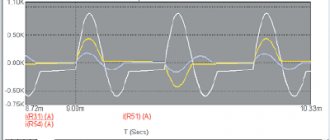
In general, it is quite simple. Let's start with a voltmeter. First, we connect terminals 10 and 11 of D1 to each other, and by adjusting R4 we set the readings to zero. Then, remove the jumper that closes terminals 11-10 and connect a standard device, for example, a multimeter, to the “load” terminals.
By adjusting the voltage at the source output, resistor R5 adjusts the calibration of the device so that its readings coincide with the readings of the multimeter. Next, we set up the ammeter. First, without connecting the load, by adjusting resistor R5 we set its readings to zero. Now you will need a constant resistor with a resistance of 20 O and a power of at least 5W.
We set the voltage on the power supply to 10V and connect this resistor as a load. We adjust R5 so that the ammeter shows 0.50 A.
You can also perform calibration using a standard ammeter, but I found it more convenient to use a resistor, although of course the quality of calibration is greatly influenced by the error in the resistance of the resistor.
Using the same scheme, you can make a car voltmeter. The circuit of such a device is shown in Figure 4. The circuit differs from that shown in Figure 1 only in the input and power supply circuit. This device is now powered by the measured voltage, that is, it measures the voltage supplied to it as a supply.
The voltage from the vehicle's on-board network through the divider R1-R2-R3 is supplied to the input of the D1 microcircuit. The parameters of this divider are the same as in the circuit in Figure 1, that is, for measurements within 0.99.9V.
But in a car the voltage is rarely more than 18V (more than 14.5V is already a malfunction). And it rarely drops below 6V, unless it drops to zero when completely turned off. Therefore, the device actually operates in the range of 7.16V. The 5V power supply is generated from the same source, using stabilizer A1.
Parameters and features of pointer voltmeters
And although we have long been accustomed to digital voltmeters, pointer ones are still found in nature.
In some cases, their use may be more convenient and practical than the use of modern digital ones.
If you get your hands on a pointer voltmeter, then it is advisable to know its main characteristics. They are easy to identify by the scale and the inscriptions on it. The M42300 built-in voltmeter fell into my hands .
At the bottom, under the scale, as a rule, there are several icons and the model of the device is indicated. Thus, an icon in the form of a horseshoe (or a curved magnet) means that this is a device of a magnetoelectric system with a movable frame.
In the next photo you can see such a horseshoe.
A horizontal line indicates that this measuring device is designed to operate with direct current (voltage).
Here it is worth clarifying why we are talking about direct current. It is no secret that not only voltmeters are pointer meters, but also a huge number of other measuring instruments, for example, the same analog ammeter or ohmmeter.
The action of any pointer device is based on the deflection of a coil in the field of a magnet when a direct current passes through this very coil. To display readings on the instrument scale using an arrow, the current must be constant.
If it is variable, then the arrow will deviate to the right and left with the frequency of the alternating current that flows through the coil winding. To measure the amount of alternating current or voltage, a rectifier is built into the measuring device.
That is why, under the scale of the device, the type of current with which it is capable of working is indicated: constant or alternating.
Further on the scale of the device you can find an integer or fractional number, like 1.5 ; 1.0 and similar. This is the accuracy class of the device, expressed as a percentage. It is clear that the lower the number, the better - the readings will be more accurate.
You can also see this sign - two intersecting lines at right angles. This symbol indicates that the operating position of the device is vertical.
When positioned horizontally, readings may be less accurate. In other words, the device can “lie.” It is better to install a dial voltmeter with this symbol vertically into the device and avoid significant tilting.
But this sign indicates that the working position of the device is horizontal.
Another interesting sign is a five-pointed star with a number inside.
This sign warns that the voltage between the device body and its magnetoelectric system should not exceed 2 kV (2000 volts). This is worth paying attention to when using a voltmeter in high-voltage installations. If you plan to use it in a 12 - 50 volt power supply, then there is no need to worry.
How to read readings from the scale of a dial voltmeter?
For those who see the instrument scale for the first time, a completely reasonable question arises: “How to read the readings?” At first glance, nothing is clear.
It's actually simple. To determine the minimum scale division, you need to determine the nearest number (digit) on the scale. As we can see on the scale of our M42300, this is 2.
Next, we count the number of spaces between the lines up to the first number or digit - in our case, up to 2. There are 10 of them. Next, we divide 2 by 10, we get 0.2. That is, the distance from one small line to the next one is 0.2 volts.
So we have found the minimum division of the scale. Thus, if the needle of the device deviates by 2 small divisions, this will mean that the voltage is 0.4V ( 2 * 0.2V = 0.4V ).
We have the already familiar built-in voltmeter model M42300. The device is designed to measure DC voltage up to 10 volts. The measurement step is 0.2 volts.
We screw two wires to the terminals of the voltmeter (observe the polarity!), and connect a dead 1.5 volt battery or any one that comes along.
These are the readings I saw on the instrument scale. As you can see, the battery voltage is 1 volt ( 5 divisions * 0.2V = 1V ). While I was taking photographs, the voltmeter needle was stubbornly moving towards the beginning of the scale - the battery was giving out its last “juices”.
In addition, I became interested in how much current the pointer voltmeter itself consumes. Therefore, instead of a battery, I connected a power supply and set the output to 10 volts - so that the instrument needle deviated to the full scale. Next, I connected a digital multimeter into the open circuit and measured the current.
It turned out that the current consumed by the pointer voltmeter was only 1 milliampere ( 1 mA ). It is enough for the needle to deviate the entire scale. This is very little. Let me explain my hint.
It turns out that a pointer voltmeter is more economical than a digital one. Judge for yourself, any digital measuring instrument has a display (LCD or LED), a controller, and also buffer elements to control the display. And this is only part of his scheme. All this consumes current and drains the battery or accumulator. And if in the case of a voltmeter with a liquid crystal display the current consumption is small, then if there is an active LED indicator, the current consumption will be significant.
So it turns out that for portable, self-powered devices, it is sometimes wiser to use a classic pointer voltmeter.
When connecting a voltmeter to a circuit, there are a few simple rules to remember.
Firstly, a voltmeter (any one, digital or pointer) must be connected in parallel to the circuit or element on which the voltage is planned to be measured or controlled.
Secondly, the operating range of the measurements must be taken into account. It is easy to recognize - just look at the scale and determine the last number on the scale. This will be the limit voltage for measurement with this voltmeter. Naturally, there are also universal voltmeters, with a choice of measurement limit, but now we are talking about a built-in pointer voltmeter with one measurement limit.
Voltmeter. A device for measuring voltage in an electrical circuit
We all know that the voltage in a household outlet is 220 V (it is worth remembering that this is not the case in all countries). But sometimes it can be more or less, and a logical question arises - how to measure the voltage? For this we need a voltmeter. And so, a voltmeter is a device that measures potential difference (in Volts) or voltage. The principle of operation of a classic voltmeter is quite simple - the current that is induced in the coil when connected to a voltage source creates a torque that moves the needle of the electrical measuring instrument. The deflection of the needle is always directly proportional to the potential difference between the measured points. It is worth remembering that the voltmeter is ALWAYS connected in parallel to the circuit in which the voltage is measured.
Retro technology, homemade products and the fight against idiocy
I don’t yet know what kind of modding project this measuring head will be used in, so I decided to write a separate post about it. I am posting the information hot on the heels, literally and figuratively: successful technology was found only yesterday.
So, in my household I had an old M24 series dial gauge, calibrated as a millivoltmeter/milliammeter. From a functional point of view it was serviceable, but the scale had clearly seen better days, so it was no longer suitable for my purposes.
Previously, when people asked me why I didn’t change instrument scales in my mods, marked in some extraneous quantities, I answered that I didn’t want to spoil the original old things. And this was true, but only half: the fact is that even if I wanted to change some scale to a new one, I would not know how to do it efficiently.
I made my first attempt to adapt this device for use in conjunction with a computer several years ago, when, based on a scan of the original scale, I drew my own and printed it on old paper.
The scale, frankly speaking, came out very poorly. It looked ugly, the yellow color of the paper did not match the other details, and the division price in the lower part of it turned out to be fractional.
Therefore, I did not use this device anywhere and put it in a drawer for a long time. But recently I took it out of there and decided to do everything right this time. First of all, I connected it to a voltage source and accurately calibrated it, putting pencil marks from 0 to 100 (it was decided to mark one of the scales as a percentage in order to use it to display a wide variety of values).
I then removed the timeline and scanned it.
I wanted the new scale to look nice and authentic. So I dug through a drawer of old pointer heads and found one that I liked best.
Using various Photoshop tools, I removed as much of the original background as possible and superimposed the resulting image on top of the scan with pencil marks. By a happy coincidence, it turned out that it was enough to just scale the new scale a little so that it perfectly matches the drawn one. Apparently, the devices have the same type of mechanisms with a nonlinear dependence of the angle of deviation on the voltage - if you look closely at the scale, you will notice that the interval from 0 to 1 is noticeably larger than the interval from 9 to 10.
The following picture shows an intermediate stage of work: some of the numbers are still missing, some areas have not been redrawn, and uncollected “garbage” is visible.
In order for the device to end up looking as close to the real thing as possible, I did not use characters from new fonts, but only copied the original ones. If I had to use the same number twice, I deliberately deformed it a little so that there would not be a perfect digital copy. This kind of pedantry may not be very healthy :-). The debris had to be removed manually, because I do not know of an automatic cleaning mechanism that would remove the dust without blurring the contours.
In the end it turned out like this:
The first scale displays percentages, the second - temperature (calibrated according to the temperature sensor datasheet, which does not guarantee the accuracy of readings below zero), and the third - processor frequency in megahertz. I left the nostalgic value “IMP / MIN” because, as they say, it is on topic. Due to the gradual compaction of the divisions, the marks on the temperature scale turned out to be very small, but it was decided to ignore this. At the very end I added an outline of the metal backing to make the scale easy to cut out and place in place.
It was possible to remove the inscriptions from the original scale using ordinary soap. If soap does not help, you can try alcohol, acetone, solvent 646, acetic acid or hydrogen peroxide - in my practice there has never been a case when this “cocktail” did not work.
But this was all just a prelude, the real witchcraft is yet to come. I didn’t even consider printing the new scale on paper, but instead began to think about how to apply the inscriptions directly onto the original aluminum plate. The easiest thing, of course, would be to load it into an inkjet printer converted for printing on hard surfaces (some cool radio amateurs make these for making printed circuit boards), but this option had to be discarded due to the lack of a suitable printer. I also remembered such a thing as metal printing, but it also requires special equipment, and I wanted to find a method that I could use at home.
Therefore, it was decided to master another technology from the arsenal of radio amateurs - LUT (“laser-ironing”). It has been described so many times on the Internet that I see no point in repeating it. In short, a design is printed using a laser printer on some smooth paper in a mirror image, after which it is transferred to the desired surface using heat. This method is used to create tracks on printed circuit boards, but in my case the last technological stage - etching - was not needed.
I haven’t used LUT before, so I decided to practice on cats first. After reading many recommendations, I chose two intermediate media - semi-gloss magazine pages and photo paper of unknown origin.
Connection process
What does a voltmeter measure?
To take readings of the network voltage in a certain section of the circuit, a voltmeter is connected to it only in parallel, regardless of the type of device, since in this case it has minimal influence on the movement of electric current. Voltage monitoring with this meter can be carried out both at the load and at the power source.
Diagram of parallel connection of a voltmeter to a network
When a voltmeter is wedged into an electrical circuit in series, it actually breaks due to the high internal resistance; accordingly, the measurements obtained will be incorrect, and in many cases a short circuit or failure of the circuit elements, including the meter, may occur.
On a note. Do not confuse a voltmeter with an ammeter, which is connected to the mains in series, since the resistance when measuring current should be minimal.
The device is connected to two sections of the circuit by clamping the wires with special electrodes or clamps.
If you need to measure sections of a DC electrical circuit with a known high voltage or you need to obtain ultra-precise data on this parameter, then you should use additional resistance, which is created by resistors - the simplest voltage dividers.
Connecting additional resistance (resistors) to the circuit to increase the accuracy of the voltmeter
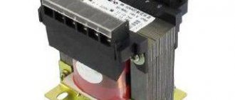
When making measurements in high-voltage AC power networks, you can use not only resistors, but also instrument transformers as additional resistance. It is with alternating current that electricians usually use voltage transformers, since they not only reduce the voltage for the end user, but also separate the measuring circuit from the power circuit.
Appearance of the voltage transformer
Rules for connecting voltmeters to a circuit:
- The correct measuring range of the device must be selected. You cannot measure high voltage with a voltmeter, which is designed for measuring the parameters of microcircuits;
- If the device reading is close to the limit value, you should work with it carefully, since a jump in the EMF can damage its windings;
- The pointer device must be positioned according to the instructions: either vertically or horizontally. When monitoring readings, it is recommended to exclude the influence of electromagnetic fields on the device and vibration waves;
- Voltmeters can be connected to a circuit that is already energized, however, at dangerous values of this indicator, it would be useful to use special gloves and a dielectric cloth (mat);
- If the arrow in an analog device gives a non-zero result before starting to take readings, then it is necessary to reset it with a regulating element - a screw;
- Periodically, it is necessary to carry out calibration measures on the device, which will guarantee the accuracy of the measurements it produces;
- When using the device for the first time, it is worth connecting it to a de-energized network - only when all the terminals and wires of the device are connected, the current turns on;
- During measuring procedures, to avoid injury, it is recommended that you familiarize yourself with the safety precautions specified in the instructions.
When monitoring voltage in different circuits, various voltmeters and additional devices (resistors, transformers for them) can be used; to obtain ultra-precise measurement results, it is important to take into account the features of each of them.
The essence of a voltmeter
In some cases, using a conventional voltmeter with a linear scale may not be very convenient. For example, to monitor the charge-discharge voltage of a car or other similar battery, a voltmeter with a scale not from zero but, say, from a value of 10 volts is more convenient. Since such batteries are usually not discharged to lower values, and if they are discharged, this only indicates their improper use, probable inoperability and significant loss of capacity.
Thus, a voltmeter with an extended scale makes it possible to monitor values in the operating voltage range (for example, 10 ... 15 volts ). And even minor deviations in values are clearly visible and displayed more clearly.
As a dial indicator (measuring head), you can use any suitable size, for example, from an old tester (voltmeter, ammeter, ohmmeter, etc.) or even small dial indicators of the recording/playback level from audio electronic equipment. In this case, you only need to calculate the parameters of the nominal values of the parts used in the circuit and calibrate the indicator scale to the new values. We tell you how to do this below.
Connection diagrams and methods
The question often arises of how to connect an ammeter, in series or in parallel. Connecting the device in question into an electrical circuit break is not difficult. For safety reasons, this procedure is performed when the power source is turned off. You need to make sure in advance that the maximum current will not exceed the permissible values of the device. Such scales are duplicated in the accompanying technical documentation. When the supply voltage is applied, readings are taken. You need to wait until the needle stops oscillating. When it moves in the opposite direction, the polarity of the connection changes. If the current is too high, additional shunting is used.
The connection diagram of the device can be direct or indirect. In the first case, the device is directly connected to the electrical circuit between the power source and the load.
Before connecting the device, you must consider:
- direct or alternating current in the electrical network;
- Is the polarity of the device correct?
- the arrow of the device should be located beyond the middle of the scale;
- limits for measuring the maximum possible current surges in the circuit;
- whether the external environment meets the recommended indicators;
- Is the measurement location free from vibration?
Connecting the device
In DC circuit
Direct current can pass through different electrical circuits. As an example, we can cite all kinds of chargers and power supplies. To repair such devices, the technician must have an understanding of how the ammeter is connected to the electrical circuit.
At home, such skills will also not be superfluous. They help a person who is not too keen on radio electronics to determine for himself, for example, the time it takes to charge the battery from a camera.
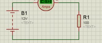
To conduct the experiment, you will need a fully charged battery with a nominal voltage of, for example, 3.5 V. In addition, you need to use a lamp of the same rating to create a series circuit:
- battery;
- ammeter;
- bulb.
The entry that is marked on the measuring device is recorded. For example, a lighting fixture will consume 150 milliamps of electricity, and the battery has a capacity of 1500 milliamp-hours. Therefore, it will work for 10 hours, delivering a current of 150 mA.
Connecting to the charger
The question often arises of how to properly connect an ammeter to a charger. When using a charger, the need arises to measure the current. This will make it possible to control the process of accumulating electricity by the battery, and avoid overcharging and undercharging. As a result, the service life of the battery will increase significantly.
When operating a large number of technical devices, it becomes necessary to control the current strength. The ammeter needles or indicators on the monitor of a discrete device will show the operator such a physical parameter. The measurements taken are needed to maintain the operating condition and to signal the occurrence of an emergency.
We recommend reading: The simplest low-frequency amplifiers using transistors