A programmable logic controller is a microprocessor device. Designed for collection, processing, transformation processes, and storage of information data. Additionally generates control commands.
Structurally, it includes several inputs and outputs to which sensors, keys and actuators are connected. The device is used in real time.
Today, many are interested in PLC, what it means, since such devices are necessary for the implementation of modern control schemes for various industrial processes.
In fact, they relate to industrial automation, which was originally created on the basis of contact relay circuits. The latter had a fixed operating logic. This necessitated a complete rework of the wiring diagram when making changes to the algorithmic formula.
Microprocessor technology quickly developed and improved, which ultimately led to the production of control systems based on industrial controllers. Despite this factor, relays still continue to be widely used, but the scope of application for such units has changed somewhat.
PLC - what is it?
The controller is the brain of the machine. The more complex the machine, the more functional the controller. The technical implementation of the brain can be different - mechanics, pneumatics or hydraulics, relay or electronic systems.
If the design uses relays or solutions with “hard” logic, then the machine can only perform certain actions - it is impossible to teach the machine other operations without interfering with its technical part. Only programmable logic controllers or PLCs have such functions.
A PLC controller is a microprocessor-based control device that is adapted for use in production. The device is programmed in simplified languages that are accessible to the user without extensive training.
Operating principle of the control unit
The signal going to the device comes from the accelerator handle. The device receives data and, based on it, changes the rotation speed of the electric motor. In order to extend the operating life of the unit, a smooth decrease in the pulse length must be ensured during deceleration. Among other things, the controller can offer the electric bike to move in reverse.
The device extends the life of the battery, which should not reach a deep discharge. To do this, a threshold charge indicator is introduced into the control unit and when it is reached, the electric motor is switched off. The controller monitors the system temperature, which prevents current overload. When selecting a control device, it is imperative to take into account the battery voltage, maximum operating current and other parameters.
PLC structure and device
The controller can be figuratively provided in the format of a mini-computer, but very compact and with features. PLCs, like PCs, consist of RAM, a processor, and auxiliary peripheral equipment. However, the point is also that industrial controllers must perform not only calculation tasks, like a PC, but also collect information from a mass of devices - these are sensors. The controller also produces signals in the circuit.
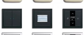
Controllers are now available in various form factors. This:
- All-in-one device. The processor, memory, outputs/inputs are combined in one housing;
- Distributed solutions - the processor module with wiring is made in the form of a separate block, and modules for output and input are connected via the bus or through interfaces.
The first models are very common, however, they are designed for operation in small objects and systems where a small number of signals need to be processed.
The second type of controllers is used much more widely in industry - production facilities with fully functional automated control systems require a significantly larger number of signals that need to be processed. If the production is large-scale, then it is more convenient to distribute input/output modules throughout the territory and combine them into a single network, which is subordinate to a separate logical controller. Such networks are called field networks or fieldbus. Sensors and executive systems are connected to this system, which are intelligent because they have this capability.
There are many types of field networks. IEC61158 standard ( IEC61158 ) includes 8 types of networks. And before the introduction of this standard, each manufacturer invented and used its own field network.
The PLC structure has the basic components:
- Processor module;
- Power unit;
- I/O modules.
The processor module is equipped with built-in memory. There are connectors for the programmer, remote devices, and for connecting to networks. Power supply is implemented as a separate unit. Modules can be discrete or analog.
Depending on how many channels there are for input and output and what type of processor, I/O modules can be installed in one CPU chassis or in several. Until the late 80s, modules for data input and output were located separately from the processor. In a standard modern type controller, the input and output module is located on the same chassis with the microprocessor. Some PLCs allow more than one microprocessor to be installed.
Smaller models are often DIN rail compatible. The most compact micro or even nano devices have the entire system, including power adapter and I/O system, in one package. Microcontrollers are sometimes equipped with built-in panels for configuration and monitoring. Most micro-solutions have a certain number of input/output channels and it is not possible to increase them. As an example - Arduino board
How to buy the right controller
Now the choice of these devices is huge, so there is no need to rush to the first models you come across on the Internet without understanding the details. The World Wide Web is not the only place where you can purchase a suitable controller. In real life, there are specialized workshops that allow you to remove wires from the control unit for the functions required by the buyer.
Most control device boards offer users maximum functionality, but it is not fully displayed. For example, it may be that recuperation is disabled, or reverse is not activated, or cruise control is not activated. When you purchase a product from such offices, these and other functions can be displayed immediately, and you will pay quite reasonable money for everything. As for the cost, the situation is as follows: there are different price segments for control units, so to speak, for any request and any wallet.
For example, in Moscow, a wide variety of products are offered. Want something cheaper? No problem: control devices for the domestic market of the People's Republic of China, manufactured according to the principle of cheap and cheerful, are developed so that you can simply ride an electric bicycle. They come mainly in 2 modes and can work with or without Hall sensors.
Further export options from China with connected displays and wireless control are offered. Overseas and German products can please with their technical perfection those users who, as they say, do not mind money - these products represent a line of expensive control devices for electric bikes.
Operating principle of PLC
Unlike microprocessor technology, the operating principle of a PLC is slightly different. The software is divided into two parts. The first part is a block of system programs. If we draw an analogy with a PC, then the controller system software acts as an operating system responsible for the operation of low-level processes. The system part of the software is installed in permanent memory and comes into operation at any time.
When the PLC turns on, the operating system starts within a moment. Execution of the user program is cyclic. The work cycle consists of four phases:
- Polling inputs;
- Executing commands;
- Setting values for inputs;
- Auxiliary operations.
The first phase of the cycle is completely provided by the PLC system control software. Then the application software, an algorithm created by the operator, takes control. According to this program, the controller will do what they want it to do. Once these commands are completed, the work is again transferred to the system software. The process of creating a PLC control application program is simplified as much as possible - the programmer does not have to think about how to manage the hardware capabilities. The operator only has to indicate what signal will be at the input and how to react to it at the output.
Connecting elements to the PLC
All controller models have terminals for connecting power - some require AC voltage up to 120 V, while others require DC voltage up to 24 V. The supply voltage depends on the device model. The input terminals are designated by the letter X - each receives a separate signal. The common wire is usually connected to the neutral of the AC source or to the minus of the DC source.
The controller body contains an optical isolator - a simple LED. With its help, the input terminal and the common terminal are connected. When voltage is applied to the PLC, the LED lights up - it is from this that you can judge that the device is working. At the output, a signal is generated using computer circuitry - the switching device is activated. Electromagnetic relays, transistors, power switches, and thyristors can be used as a switching device. The outputs are designated by the letter Y. Each output has an LED indicating that the device is working.
Inputs and outputs
Any controller has three types of inputs: discrete, analog, and special.
Discrete input
One input can only accept one signal and it will be binary. The input can be either on or off. One input is 1 bit . The appropriate equipment is connected to this input.
If the state of the devices cannot be described in 1 bit , then several discrete inputs are used to operate such equipment.
The system software must be equipped with a driver. It counts the physical values of each RAM input. Due to this, programmers do not need to understand how the controller works inside. Discrete input - bits that can be read and changed from the device's RAM.
Analog input
An electrical analog signal is a voltage or current level corresponding to certain physical quantities. This can be the value of temperature, pressure, weight, position, speed of movement, speed of rotation. Since a PLC is primarily a computing device, the analog signal is converted to digital. This results in a discrete variable.
Special entrance
Ordinary entrances can satisfy almost all needs. The need for special inputs appears when there are difficulties in processing signals.
PLCs are equipped with specialized inputs that allow you to measure duration, record edges, and count pulses. For example, to determine the position of shafts, sensors are used that can produce pulses per revolution. The frequency can be very high. Even on powerful processors the process takes a long time. In such situations, specialists are needed. inputs capable of primarily processing information.
The second type of such inputs are inputs that can instantly trigger user commands with interruptions to the execution of the main software.
Discrete output
Only one signal can be switched with one output. Various actuators can be used as output loads.
Nintendo Offer: Nintendo Switch Pro Controller
The Nintendo
Switch Pro Controller has been praised since its launch for its extremely comfortable design and excellent gyroscopic sensors that can be transferred to PC. The controller uses a fairly standard Xbox-style layout, save for some minor changes such as the order of the face buttons (for example, the "A" and "B" buttons are swapped). This controller also seems to be more powerful than others and lasts for 40 hours on a full charge. It connects via standard Bluetooth, but relies on DirectInput instead of Xinput, so running it through the Steam Controller Configurator is highly recommended - especially since it powers the gyroscope.
Types of PLC
Devices are qualified as follows:
- Number of channels for data input/output;
- Arrangement of modules for input/output;
- Purpose;
- Installation method;
- Programming languages.
Based on the number of channels for input/output, PLCs are divided into classes:
- Nano PLC controller – often has built-in capabilities, contains up to 16 channels;
- Small – from 16 to 100 channels;
- Medium systems for working with 100-300 inputs and outputs - a typical representative of the 110 Aries PLC;
- Large models with the ability to process 300-2000 inputs/outputs;
- Extra-large models - from 2000 or more channels.
Based on how the modules are arranged, controllers are divided into:
- Monoblocks - the I/O module is not separated from the controller and must be replaced. The device looks like a candy bar with an input/output module. Often, models have a small number of channels and are characterized by low power;
- Modular ones consist of a common basket or chassis where the processor is located, as well as replaceable modules with inputs and outputs. Modules are selected based on the problem being solved. The controllers are equipped with a number of slots - from 8 to 32. A modular design is also possible, where each module is connected via a bus. .
- Distributed controllers - modules are manufactured in separate housings and are connected to the central processing unit via a network. The range can be up to 1.2 km.
PLCs also differ in purpose - these are universal general industrial devices, communication devices, PID controllers, systems for robotics, for controlling movement and positioning.
According to the installation method, industrial controllers can be divided into:
- Panel;
- For DIN rail;
- Rack-mounted;
- Bodyless.
By programming languages, models are distinguished that are programmed in the language of PLC systems MEK 61131-3 and in classical languages such as C, C#, Visual Basic, Scala.
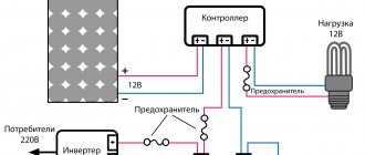
Connecting the controller on an electric bike
Basically, when connecting the controller to an electrified bicycle, the user should not have any significant difficulties. However, if you have never done this before, you may be intimidated by the large number of wires of different colors. If you purchased a controller and MK in one set, then their connectors must match each other.
Basics of PLC programming. Relay and controller
The logic is loaded into the PLC using software. This software determines which outputs will be energized and what input conditions are needed for any changes. The control program is similar to the operating diagram of a physical relay, but there are physically no relays, no wires, no coils. All these elements are imaginary. The software is developed and reviewed on a PC connected to the controller interface.
There is a button, a controller and an indicator. When the button is not activated, no signal will be sent to the controller input. Software indicating an open input will not send a signal to the output. So, there is no current at the output and the lamp will not light.
If the button is pressed, the corresponding signal is sent to the input channel. The contacts will switch to an active state, like a physical relay. In this case, the controller contact that was opened earlier will close and the program will send a signal to the output. When the output contact is energized, the indicator will light up.
The contacts with the indicator are connected physically. And the signal is virtual. However, all elements exist only in computer software, but not as physical ones. But the relay principle is used here. You can also set conditions in the program that will be checked and fulfilled by the controller.
To create the same circuit, but based on physical hardware components, you will need three relays, with two open contacts - each of them will be used. But with the help of a PLC, you can use as many contacts for each input as you want without adding unnecessary equipment.
Control commands in relay logic language are simple and understandable for electrical engineers. All logical operations are visible on the graphical interface. This is an electrical circuit with closed or open contacts. If current flows through the circuit, that is true. If no current flows, then the state is false.
The basis of the control program are logical expressions consisting of operands and variables. The program also consists of statements. Operators are commands in a programming language.
A PLC software engineer today is more of an engineer than a programmer. Nowadays there is no need for complex languages, writing assembly inserts. It is enough to use standard function blocks.
Why do you need a computer
Using a computer, a logical connection is created between the input and output terminals. The software used to compose the logic allows you to send a virtual signal to the controller and see how it will act under certain conditions. After the logic is embedded inside the PLC, the computer turns off and the controller operates independently. He will be able to carry out all the commands that were given to him at the programming stage without outside help.
Programming environment
The standard for PLC programming is the MEK languages. In the early 90s, CoDeSys . the IEC 61131-3 standard for PLC operation. The software is in great demand due to its free license.
Now this software package has grown significantly. In addition to the standard code editor, debugger and compiler integrated into the system, it also includes a configurator for controllers, industrial networks, an editor for creating mnemonic diagrams, a debugging server, OPC and DDE . Many PLC manufacturers offer this environment as a basic tool for work.
Types of controllers
These devices are divided according to several criteria.
By type of feedback:
1. For use with Hall sensors.
2. Without them.
3. Universal controllers. They combine the first and second points.
By type of output signal:
1. Rectangular shape (meander). Similar gadgets are used on cheaper models of electric bicycles, and they themselves are inexpensive. They enable the user to obtain a higher rotation speed, but at the same time, this leads to an increase in the noise of the electric motor. And the engine is noisy due to microvibration of the windings under the influence of a signal of this form.
2. Signal in the form of a sine wave. The rotation speed is lower, but the sound of the electric motor rotating is completely absent.
3. There is also an intermediate version - a “modified sinusoid”. This variation can be called a “smoothed meander”. However, this variety did not gain popularity among users.
Controllers may have different reactions to signals coming from the accelerator handle: in one case you will regulate the speed, in the other - the power or thrust of the engine.
PLC programming languages
Control programs for controllers are developed in languages that are created not for programmers in the modern sense, but for automated process control engineers.
The simplest and most popular tool is considered to be a set of ready-made modules and a configurator that allows you to assemble the modules into a control circuit. Until recently, each PLC manufacturer had its own language. But by the mid-90s the situation had changed. Languages have been standardized.
IEC 1131.3 standard defines five languages:
- Ladder Diagram Language LD is a traditional relay-based language where algorithms are represented as diagrams;
- FBD – represents a configurator and standard subroutines;
- SFC is a sequential circuit language. A tool that is close to traditional programming and implements algorithms with sequential control;
- ST is a structured type language. Pascal- like language with support for structured programming;
- IL – instruction language. It is a low-level tool like Assembler , but it is not focused on microprocessor architecture. It is mainly used to create fast programs.
What does it include
Now this is a very complex technical unit, which has been significantly improved since its development. A modern average controller has its own microprocessor, registers of external devices, thanks to which the device interacts with the CPU, RAM, ROM, and matching (buffer) circuits. That's what a controller is. To imagine what this complex device is, imagine a simplified specialized electronic computer that deals only with a certain range of actions - for example, it interacts with a keyboard that is connected to a computer. As soon as a key is pressed, this information is transmitted to the central processor, where it is processed accordingly.
Remote control and monitoring
The controllers have flexible capabilities for communicating with other equipment. These capabilities allow you to remotely control devices, as well as integrate PLCs into automated control and data acquisition systems.
A operator terminal or HIM is a visualization device. It can be built-in or connected by cable. There are many different types of such solutions - from simple digital ones with buttons to serious touch ones with the function of online monitoring and parameter correction.
SCADA is an abbreviation for supervisory control and data acquisition system. These are software packages that allow you to develop applications in real time. The package also has tools for data collection and processing, archiving and display or management.
The web interface allows you to access the PLC over local or wide area networks. Depending on the functionality, the controller may not have an operator panel, but there is a port for connecting the PLC to Ethernet. Then the device can be configured remotely via the web interface or from a laptop.
A more advanced solution is implemented in the Siemens - an embedded web server. It allows you to monitor as well as manage the system. Today, PLCs implement cloud connectivity functions for remote control.
Premium Update: Xbox Elite Wireless Controller Series 2
The Microsoft
Elite Controller is a step up from the standard Xbox controller in every way, and it has a lot of premium features at a correspondingly high price. This controller is highly customizable both at the software and hardware levels; you can swap out the joysticks and D-pad for alternate designs and sizes, adjust trigger dead zones and remap inputs via software, and use the paddles on the back of the controller for additional actions. Add in an improved design with comfortable grips and a rechargeable battery that lasts up to 40 hours, and you have a great controller.
And just like a standard Xbox Wireless Controller, you shouldn't have any problems connecting the Elite to your Windows PC via Bluetooth or an adapter (sold separately).
PLC Manufacturers
There are a lot of companies that manufacture industrial controllers - these are:
- Advantech,
- Delta,
- VIPA,
- Mitsubishi Electric,
- WAGO I/O,
- Phoenix Contact
- and many others.
Russian PLC manufacturers:
- Kontar,
- Aries,
- Segnetics,
- Fastwel,
- Tekon.
What to look for when purchasing
It all depends on the type of production and the tasks that need to be solved, but there are also universal solutions. Key points:
- Universality of the programming environment for different platforms;
- Controllers with distributed input/output;
- Devices with built-in input/output;
- PC connection;
- CPU and I/O system duplication;
- Web-enabled PLC;
- PLC with PC type processor;
- Portable devices for creating programs.
The most important point here is the first point. You should not try to find the most affordable equipment on the market - the process of retraining specialists will reduce all possible savings to zero. It is worth choosing several manufacturers and collaborating only with their products.
Other experts argue that the most important thing is software. The differences in the comfort of using software products are much greater than in PLC hardware.
Programmable control devices
Programmable control devices are increasingly in demand among users. They make it possible to change indicators: from the magnitude of battery and phase currents, to phase advance angles and field weakening. Connection to a computer is made via a USB cable, and with mobile devices, such controllers are connected via Bluetooth.
When choosing a control unit, pay attention to the auxiliary functions: reverse, recuperation, individual power output for lighting devices, modes for selecting speed and power level, etc.
LED chandelier controller circuit
Let me remind you that this remote radio-controlled switch (control unit) can be used not only in chandeliers, but also in other electronic devices. You can switch any voltage (within reasonable limits, with a little modification of the printed circuit board), and any currents (the current is limited by the relay current, but additional contactors can be installed).
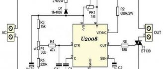
The controller diagram is shown below:
Controller circuit for chandelier with control panel Sneha B-827
The diagram was taken by me from the site www.tokes.ru, thank you!
Having this diagram, you can safely take on repairing the controller, and the chances of success are quite high.
To examine the diagram in detail, I enlarged it and divided it into 6 conventional parts:
LED chandelier controller circuit broken down into parts for easy understanding
Let's look at each part separately.
Power supply and switching
This part of the circuit includes input and output circuits, and relay contacts through which the load is powered.
The relay coils are included in the 3rd part of the circuit.
Zero and phase come next.
Power supply 220 – 12 V
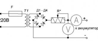
This part receives 220V voltage, zero and phase. Zero passes to the diode bridge through a choke, which to some extent eliminates high-frequency power supply noise, which can lead to failures. Capacitor C1 serves the same purpose.
The phase to the diode bridge comes through the quenching capacitor C2, which is shunted by resistor R1 for safe operation.
Each diode of the diode bridge is also shunted by a capacitor to minimize the high-frequency component of the supply voltage.
The output of the diode bridge is loaded onto filter capacitors C3 and C4, which serve to filter the low-frequency and high-frequency components of the bridge output voltage. The voltage is stabilized by a chain of series-connected 12V zener diode VD2 and limiting resistor R4.
As a result, at point A a DC voltage of 12.5-15V is generated in relation to the neutral wire (minus the diode bridge).
Key transistors
Key transistors are essentially amplifiers of a discrete signal that comes from the decoder. They are included according to the classical scheme.
Power circuit 12 - 5 V
Next, the 12V voltage is supplied to the +5V power stabilization circuit. The voltage at the input of this stabilizer is reduced and stabilized by a chain of resistor R6 and a 12V zener diode VD4 and supplied to the 78L05 integrated stabilizer. Further, the stabilized +5V voltage is additionally filtered by capacitors C5 and C6, since a special quality of constant voltage is required.
Radio module
The +5V supply voltage is supplied to power the radio module. The purpose of the radio module is to receive a signal from the control panel from the radio air and output it in such a form that a decoder can decode it.
Radio decoder
The decoder receives a signal at frequencies, each of which corresponds to a pre-designated signal. What is going on in the decoder is a company secret; the datasheet for the HS153SP-J chip could not be found.
If anyone has it, please share!
The “waste product” of the radio signal decoder is discrete voltages of the order of +5V, which open the key transistors.
Anyone who would be interested in aspects of the circuit’s operation that I didn’t mention, or who has something to complement or reproach me with, write in the comments!
Controller - Wikipedia (with comments)
Share your knowledge:
You are not a slave! Closed educational course for children of the elite: “The true arrangement of the world.” https://noslave.org
Material from Wikipedia - the free encyclopedia
Controller
(English
controller
- regulator, control device):
- Controller
is a control device in electronics and computer technology.
A game controller
is an information input device used in console and computer games. - A domain controller
is a server that controls an area of a computer network (domain). - Interrupt controller
is a chip or built-in processor unit that is responsible for the ability to process interrupt requests from different devices. - The electric motor controller
is a multi-stage, multi-circuit switching device with manual control. - Microcontroller
is a chip that controls electronic devices. - An industrial controller
is a control device used in industry and other industries to automate technological processes, in everyday life - for climate control, etc. - Programmable logic controller
is an industrial controller optimized for logical operations. - The system controller
is a chipset component that organizes the interaction of the processor with RAM and forms the computer platform.
- traction and/or braking control in locomotives, electric trains, trams
is the same as a regulator.
is one of the components of the MVC pattern.
is an electronic control unit for the engine and other vehicle systems.
see also
o-ili-v.ru
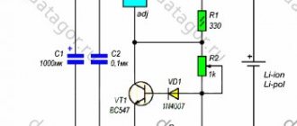
Update: Simplified chandelier controller diagram
Reader Vadim sent a slightly different controller circuit, see comments dated December 24, 2022 and later.
Diagram of a control unit for an LED chandelier controlled from a radio remote control
There is a small “inaccuracy” in the diagram. Instead of a jumper after L1 there should be a filter capacitor!
I will briefly consider the operation and differences of this scheme from the previously published one.
Up to the point of the first stage of the +14.3 V power supply circuit, the circuit is practically the same. At this point, 4 voltages are indicated, which correspond to the number of switched on relays: 0/1/2/3. Instead of key transistors, the ULN2001 microcircuit is used, which performs the same function of key cascades.
Next, the voltage is applied to a 470 Ohm resistor, and using a zener diode VD7 is converted to a voltage of about 5 V.
Next, everything, as in the first version of the circuit, is a radio module and a signal decoder.
How the repair of the chandelier control unit ended in this diagram - read in the comments after December 24, 2022.
Why do you need a controller? | The magic of computer knowledge
It just so happens that generations of computer equipment change very quickly, and what was considered modern 2 years ago is now backward and out of production. But what should a consumer do who does not expect to replace the entire complex of computer devices every 3 years, but only wants a new system unit, leaving behind the old printer, scanner or TV Tuner, and it turns out that their ports are missing on the new system unit or laptop, because What are considered obsolete? But if it’s the other way around: a person wants to connect a modern digital camera or several USB devices to an old system unit, but there aren’t enough sockets. In all these cases, a wide variety of controllers help. They can be either external for laptops or in the form of boards inserted into the PCI port of a standard PC. A controller is an adapter and a splitter, to put it simply. Using 1 controller board, you can add 4-6 USB ports to an old PC, some of which will be located on the back of the PC, and others will be inside the block on the controller board itself. The purchased controller will not always be compatible with your PC and it is quite possible that you will have to select it, changing it to a controller from another manufacturer, otherwise the PC will freeze and do other unpleasant things.
Most PCs also lack the 1398 port, which is actually also part of USB and is used by many camcorder manufacturers to connect them to a PC. This port is often used in USB hub controllers in conjunction with standard USB ports. Also, almost all modern PCs lack an LPT port, which is used by most models of outdated, but still working, printers. To use these ports, there are also controllers that are inserted into the PCI port, as well as external controllers - adapters from LPT to USB (though they do not always work). Also do not forget about other adapters with a USB interface. These are PCI-LPT adapters for a desktop PC or PCMCIA LPT for a laptop.
youtoall.ru