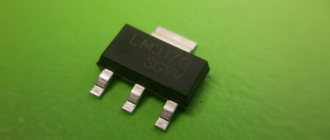
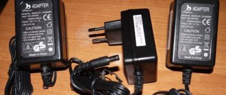
How to solder a resistor to an LED
If your circuit does not provide for current limitation by the so-called driver, then you can use resistors the old fashioned way.
It is impossible to connect LEDs directly to the network, since in addition to the increased current, it is also variable. The resistor and driver convert the current to direct current.
Each LED ideally needs a separate resistor. This is if there are few diodes. If there are, for example, a hundred of them, as in some garlands, or even a couple of dozen, you will have to purchase a driver.
If you are encountering the concepts of “resistor” and “driver” for the first time, we have selected visual instructions:
The resistor must be connected in the circuit after the power supply and before the LED. It just solders. In the chapter “Features of soldering” we left a video on how to solder any contact (see above). There are no special features here. The only thing that can be doubted is the choice of flux, that is, a substance that cleans the contact surface from oxide and/or grease film. As an option - a special paste.
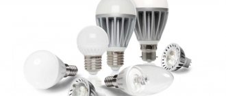
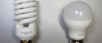
Light-emitting diode
LEDs are the basis of our lamp. It is necessary to decide on their number and type. It is logical that the power of the assembled lamp will depend on their number. Of the types, when choosing between high-power and low-power LEDs, it is advisable to choose the high-power ones. This is primarily due to difficulties during assembly. Since in order to replace one 1 W LED you will have to use from fifteen to twenty low-power ones, the work with a soldering iron will be many times more. Therefore, the best option is powerful ones. They, in turn, are divided into two subtypes - output or surface mounted. To simplify the design, it is easier to use output ones. And power - it is advisable to stop at 1 W.
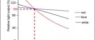
LED colors
Be sure to take into account what color the LED emits. This determines what voltage drop they will have at the same current strength. For example, with a supply current of 0.35 A, the voltage drop for the red LED elements is approximately 1.9-2.4 V. The average power is 0.75 W. A similar model with green color will already have a drop in the range of 3.3-3.9 V, and a power of 1.25 W. Therefore, if you use a 220V LED driver circuit with conversion to 12V, you can connect a maximum of 9 elements with green color or 16 with red color to it.
Brief review and testing of popular LED lamps
Although the principles of constructing driver circuits for various lighting devices are similar, there are differences between them both in the sequence of connecting the elements and in their choice.
Let's look at the circuits of 4 lamps that are sold in the public domain. If desired, you can repair them yourself.
Image gallery
Photo from
Driver for disassembled lamp BBK P653F
Compact lamp Ecola 7w
Collapsible analogue of Ecola GU5.3
Jazzway 7.5w GU10 – suitable for repair
If you have experience working with controllers, you can replace the elements of the circuit, resolder it, and slightly improve it.
However, meticulous work and efforts to find elements are not always justified - it is easier to buy a new lighting fixture.
Option #1 – LED lamp BBK P653F
The BBK brand has two very similar modifications: the P653F lamp differs from the P654F model only in the design of the emitting unit. Accordingly, both the driver circuit and the design of the device as a whole in the second model are built according to the design principles of the first.
The board has compact dimensions and a well-thought-out arrangement of elements, for the fastening of which both planes are used. The presence of ripples is explained by the absence of a filter capacitor, which should be at the output
It's easy to spot flaws in the design. For example, the installation location of the controller: partly in the radiator, if there is no insulation, partly in the base. The assembly on the SM7525 chip produces an output of 49.3 V.
Option #2 – Ecola 7w LED lamp
The radiator is made of aluminum, the base is made of heat-resistant gray polymer. On a half-millimeter thick printed circuit board there are 14 diodes connected in series.
Between the heatsink and the board there is a layer of heat-conducting paste. The base is fixed with self-tapping screws.
The controller circuit is simple, implemented on a compact board. The LEDs heat the base board to +55 ºС. There is practically no pulsation, radio interference is also excluded
The board is completely placed inside the base and connected with shortened wires. The occurrence of short circuits is impossible, since there is plastic around - insulating material. The result at the controller output is 81 V.
Option #3 – collapsible lamp Ecola 6w GU5.3
Thanks to the collapsible design, you can independently carry out repairs or improve the device driver.
However, the unsightly appearance and design of the device spoils the impression. An oversized radiator increases the weight, so additional fixation is recommended when attaching the lamp to the socket.
The board has compact dimensions and a well-thought-out arrangement of elements, for the fastening of which both planes are used. The presence of ripples is explained by the absence of a filter capacitor, which should be at the output
The disadvantage of the circuit is the presence of noticeable pulsations of the light flux and a high degree of radio interference, which will certainly affect the service life. The controller is based on a BP3122 microcircuit, the output value is 9.6 V.
We discussed more information about Ecola brand LED light bulbs in our other article.
Option #4 – Jazzway 7.5w GU10 lamp
The external elements of the lamp are easily detached, so you can get to the controller quickly enough by unscrewing two pairs of screws. The protective glass is held in place by latches. The board contains 17 diodes with serial communication.
However, the controller itself, located in the base, is generously filled with compound, and the wires are pressed into the terminals. To free them, you need to use a drill or use desoldering.
The disadvantage of the circuit is that the function of a current limiter is performed by a conventional capacitor. When the lamp is turned on, current surges occur, resulting in either burnout of the LEDs or failure of the LED bridge
There is no radio interference - all thanks to the absence of a pulse controller, but at a frequency of 100 Hz there are noticeable light pulsations, reaching up to 80% of the maximum value.
The result of the controller is 100 V output, but according to the general assessment, the lamp is more likely to be a weak device. Its cost is clearly overestimated and is equal to the cost of brands that are distinguished by stable product quality.
We presented other features and characteristics of lamps from this manufacturer in the next article.
Types of LEDs
Due to different approaches to assembling semiconductor chips, it was possible to create the following types of LED emitters:
- DIP - LED lamps made on the basis of a crystal with a lens placed on top and two lead conductors. This option is the most common in practice and is used to organize lighting in various lighting devices;
- The so-called “Piranha”, partially reminiscent of the previous design, but having four terminals. Increasing the number of contacts increases its reliability and improves heat dissipation (see figure below);
Piranha lamp
LED lamp repair
Additional Information. Such LEDs are mostly used in the automotive industry.
- SMD LED emitters can be placed on flat surfaces, due to which it is possible to reduce the dimensions of the lamp and also improve heat dissipation properties. They are available in a wide variety of designs and are used in modern light sources;
- Products manufactured using COB technologies, according to which the chip is soldered directly into the board. Due to this device, the semiconductor ice junction is reliably protected from oxidation and overheating. At the same time, the intensity of the diode glow increases significantly.
Note! The peculiarity of the above versions is that if the LED burns out, it will have to be replaced completely, since it is impossible to repair these products by replacing a separate chip.
Another disadvantage of such LEDs is their small size, which forces them to be assembled in groups of several pieces. In addition, the crystal built into them gradually ages, as a result of which the brightness of the ice emitter decreases over time. Next, we will consider the design of a 220V LED lamp.
Structural assembly diagram
How an LED lamp will work directly depends on the manufacturer and price of the product. Differences can be seen if you remove the diffuser
First of all, you should pay attention to the quality of soldering of chips, as well as connecting wires. Cheap light bulbs last less than high-quality and expensive ones
Low quality Chinese light bulbs
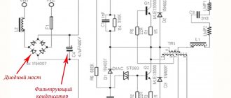
When purchasing a light bulb for no more than $3, you should not count on a symmetrical arrangement of LEDs on the board. This suggests that the soldering was done manually and in a hurry, and the wires were selected with a minimum cross-section. There will be no reliable driver here either. Instead, a transformerless circuit with a rectifier and a capacitor is implemented.
Diagram of a Chinese light bulb.
If you have to diagnose and then repair lamps of this type, you must adhere to special safety precautions. Each element that is part of one circuit may be under voltage that is dangerous to humans. If you accidentally touch one of the live parts, you may receive an electric shock. The same thing can happen if the multimeter probe accidentally slips and causes a short circuit.
Branded LED lamps
Expensive and high-quality light bulbs have a pleasant appearance, but this is not all the advantages. The quality of the element base will be significantly higher than that of a Chinese analog purchased at a low price. The installed driver is complex. One of the ways to assemble it involves installing a pulse transformer, as well as a current converter, which further stabilizes the resulting load.
High quality LED lamp.
The transformer may not be installed. The main load will be directed to the microcircuit that stabilizes the input voltage, which:
- has a negative feedback system;
- possibility of dimming;
- maintains current with a specified pulse width.
Circuit without transformer.
By choosing a high-quality 220 V LED light bulb with a current driver, the buyer receives a device protected from interference and surges in the network that meets the characteristics specified in the passport. The radiator installed here will ensure rapid heat dissipation. This light bulb will last more than 5 times longer than a cheap Chinese one.
Typical breakdowns
Since you have decided to repair an LED light bulb with your own hands, it is assumed that you have a tester or multimeter and you know how to carry out basic measurements. You will also need a soldering iron, but with a thin tip and low power. You can do without it, but you will have to look for a replacement. You also need to know at least a little how to solder with a soldering iron. You should also have tweezers, wire cutters and utensils. Utiki or duckbills are hand tools that look like miniature pliers with long grips - they are convenient for holding small parts, but you can get by with tweezers. And also spare parts. They will have to be purchased as the malfunction is identified. It's good if there is a second non-working lamp. It can be used as a donor to take the necessary parts from there.
The declared service life of LED lamps is almost half a century, and after six months several non-working pieces accumulate
Yandex.RTB RA-1479455-8
LED breakdown
As already mentioned, in an LED light bulb the crystals are connected in series. From the output of one, the wire goes to the input of the other and so runs around all the elements. The scheme is very simple. But if at least one crystal is not working, the light bulb will not light. And crystals often fail, so the first thing we do is check them. Moreover, they are easy to find in any model. A circuit diagram is not needed for verification.
First, carefully examine all the crystals. Those that “feel” normally have a light, even color. Dark spots should alert you. If there are dark, almost black dots on the crystals, these LEDs are most likely broken. We are definitely changing them. If the surface is a little darker, the crystals are still shining, but are on their last legs and will soon burn out, then it is also better to replace them now.
A burnt-out LED has a dark spot on the surface
To check whether the LEDs are working or not, you can use a multimeter. It is switched to the dialing mode, the probes are applied to the LED contacts. If a small current is needed to operate the LED, the working LEDs light up. The second test option is a 3-4 Volt battery, the contacts of which have wires soldered to them. We apply these wires (observing polarity) to the crystals. The working ones light up, but the faulty ones remain dark.
How to desolder damaged LEDs
Up to this point, everything is simple and clear; repairing an LED light bulb does not present any difficulties yet. Now we need to decide how to solder small LEDs. The whole point is that they are soldered onto a substrate that conducts heat well. That is, by heating the contact of one LED, you simultaneously heat the entire board. If you use a low-power soldering iron, it will take too much time. Powerful is also not an option, since it is very easy to overheat. The maximum temperature that crystals can withstand without consequences is 80 °C. With further heating, destruction quickly occurs, so when repairing an LED light bulb, the main task is to cause as little damage as possible to the remaining elements.
Spot heating still won't work, but you can try to cause minimal damage to neighboring crystals. To do this, we first bite out/break out the crystal plate, and heat the remaining metal legs with a low-power (20 W) soldering iron and remove it.
Soldering damaged LEDs
If you don't have a low-power soldering iron, you can use an iron. It must be firmly secured (for example, using a clamp) and set to medium mode. To minimize the “heating field” it is better to use the tip of the iron. In this case, we will heat the entire board. More precisely, we will heat the edge on which the damaged LED is located, but the entire board will warm up. And this is the disadvantage of this method - from overheating, the crystals become cloudy and quickly fail. Therefore, the trick is to quickly remove the damaged crystal as soon as possible.
Before starting work, we color all faulty crystals with a marker. We turn the board so that the place with the burnt elements is on the iron platform. We constantly pull the damaged element up, holding it with tongs. As soon as it comes off, we try the damaged ones located nearby. If they come off, great. No - we rotate the board so that the damaged element heats up more. Then we immediately remove the board and leave it to cool. No special means for quick cooling! Just put it down and let it cool on its own.
How to solder new LEDs
Contact pads remain in place of the soldered LEDs. We apply a drop of soldering flux to them, put the good ones on top (observing the polarity) and heat them up again, but this time we press on the crystal. When its legs “enter” the solder, remove the board or turn it over. If there is no LED, you can solder a piece of wire instead. The lamp will shine a little dimmer, but it will work. Yes, this only works if there are ten or more crystals on the board.
In some cases, jumper wires can be used instead of burnt-out LEDs
The video shows another replacement method. You need to find a similar LED on the strip, cut it out and solder it together with the substrate in place of the removed one.
Another way to solder small LEDs. It seems to be the most realistic without the use of special equipment. You can remove the diodes using a small gas torch.
Damage to the driver
If all the LEDs are visually normal or have already been replaced, we continue repairing the LED light bulb by looking at the driver. Some damage is easy to identify visually. Blackened or cracked resistors, swollen capacitors. If you look closely, this is all noticeable. If nothing is visually determined, we take a tester and check the integrity of the components.
There may be burnt resistances and swollen capacitors
It also happens that all the elements are absolutely normal, but the LED light still does not light up. Most likely this is a bad build. You need to check all solder joints. If you do not warm up the soldering area enough, over time the contact will deteriorate or disappear completely due to constant temperature changes. In the first case, the light is either on or off. In the second, it simply stops working. We hold all solder joints up to the light and look carefully. If we find a crack in the solder joint, that’s it. Cold soldering. Next, we simply warm up this place well with a soldering iron.
Cold soldering is one of the reasons why LED lamps fail
Diode bridges very rarely fail, so we check them last. If the diode is broken, we unsolder it, check it again (in theory, they should only be checked by unsoldering it), if the damage is confirmed, we install a similar one. Don't mix up the connection, otherwise nothing will work. In general, repairing an LED light bulb is not too difficult a task. It will cost significantly less than a new light bulb. And you, along the way, can improve the design. As a result, LED light bulbs will burn out less often. Either way, you have (almost) nothing to lose.
Types and types of LED lamps.
There is no clear classification for LED lamps: products are produced in too many different shapes, colors and configurations.
By method of use:
- General purpose light sources for lighting apartments and offices. Characterized by a dispersion angle from 20 to 360.
- Directional light products. Such light bulbs are called spots. They are used to create lighting or highlight interior areas in a room.
- Linear type products, similar to conventional fluorescent lamps. Manufactured in the form of tubes. They are used in technical rooms, offices, store rooms and other spaces where fire safety is important. They create bright, beautiful lighting that will highlight the necessary details.
According to their purpose, LED lamps are divided into:
- Products for outdoor use. Manufactured in a dust- and moisture-proof housing.
- Products for industrial purposes, public utilities. Supplemented with a vandal-proof durable casing. They are manufactured with special requirements for lighting characteristics: stability, service life, operating conditions.
- Household lamps. They are characterized by low power, stylish design, electrical and fire safety, quality of luminous flux (color rendering index, pulsation coefficient, etc.).
Based on the voltage consumed, there are also three types of lamps:
- Powered by 4 V. Low-power LEDs that consume from one to 4.5 V. They emit light of different wavelengths from infrared to ultraviolet.
- Powered by 12 V. This voltage is safe for humans, so these light sources are suitable for rooms with high humidity. They are often produced with pin sockets, which complicates the connection process. An additional difficulty may be the need for a special power supply that will reduce the mains voltage to 12 V. Convenient for use by car enthusiasts and tourists: they can organize lighting from a battery.
- Powered by 220 V. The most common type. Widely used for household needs.
Types of socles.
In order for LED light sources to fit into the existing power supply scheme of houses, they are equipped with screw bases. As an alternative to halogen-type lamps, lamps with pin bases are produced. The main types are presented in the table.
| Base type | Purpose | Photo |
| E27 | The most common screw type for household light sources. | |
| E14 | Screw base for low-power lamps. | |
| E40 | Screw base for powerful light sources (mainly outdoor ones). | |
| G4 | Pin contacts for small light bulbs. | |
| GU5.3 | Pin contact for furniture and ceiling light sources. | |
| GU10 | Similar to GU5.3, but the contact spacing is 10mm. | |
| GX53 | Pin contact for flat luminaires. | |
| G13 | Contact similar to fluorescent tube lamps. |
Installation of LED lamps for 220V AC circuits
LED light bulbs consist of the following components:
- Base (E27, E14, E40 and so on) for screwing into the socket of a lamp, sconce or chandelier;
- Dielectric gasket between the base and the housing;
- A driver on which a circuit is assembled to convert alternating voltage into a constant voltage of the required value;
- A radiator that serves to remove heat from the LEDs;
- A printed circuit board onto which LEDs are soldered (sizes SMD5050, SMD3528, and so on);
- Resistors (chips) to protect LEDs from pulsating current;
- Light diffuser to create a uniform light flux.
Important nuances
There are many systems according to which LED lighting operates on alternating current with a nominal value of 220 Volts. Moreover, all of them, together with the ballast circuit, are designed to solve three main problems.
- Convert 220V AC network current into pulsating current,
- Level out the pulsating current, making it constant,
- Achieve current levels of 12 Volts.
If you want to build a device that is powered by a regular network, you will have to deal with some basic problems to connect it.
- Where to place the circuits and the LED-based device itself. After all, diodes will need their own place.
- How can you isolate an LED lighting device?
- How to ensure the necessary heat exchange for connecting a lamp.
Of course, you can safely purchase the popular E27 lamp. This diode device is one of the most popular on the market and works perfectly from a regular household network.
Resistor circuits
A simple driver option for a homemade LED lamp consists of two 12 kOhm resistors. Two strips of LEDs are soldered between them, alternating directions. On the side of the first resistor, one strip is connected by the cathode, the other by the anode.
The anode of the first strip and the cathode of the second, respectively, are soldered to the second resistor. With this connection, the chains of LEDs light up alternately, so that the beam from the lamp becomes even and does not irritate the eyes at all. This type of lamp is perfect for the role of a table lamp.
Circuit with a quenching capacitor
The number of LEDs is at least 20, usually 40 are connected. With a larger number, assembly becomes much more complicated: the legs of the diodes are located too close. You can use more powerful diodes - then their number is reduced to 4-6.
In this case, the circuit must be recalculated by selecting new values of resistors and capacitors. Special online calculators located on websites dedicated to electrical engineering will help with this.
Types of schemes
The driver is needed to stabilize the voltage and is assembled using circuits on capacitors and transformers. The second option is more economical, and the first is necessary to create a powerful lamp. In addition, there is another type of circuit - inverter. They are used in the production of dimmable lamps and a large number of chips.
Pulse drivers
Compared to a linear driver, which uses a capacitor, a pulsed driver has effective protection against network instability. To take a closer look at an example of a pulsed diode lamp circuit, we use model CPC9909. The efficiency of this product reaches 98%, so without exaggeration it can be considered one of the most economical and energy-saving.
Driver "CPC9909".
Connection diagram BP3122
The device can be connected to high voltage (550 V) thanks to the built-in driver with stabilizer. This simplified the circuit and reduced the cost of the device.
A switching driver connection is used to activate lighting in the event of an emergency, and is an example of boost converters. At home, based on the CPC9909 driver model, you can assemble a lamp that will be powered by batteries or a driver, but the power will not exceed 25 V.
Dimmable Drivers
Using a dimmable driver, the brightness of the LED lamp can be adjusted, which will allow you to set the required level of lighting in each room and reduce the brightness of the light during the day. The devices are used to highlight certain interior items.
Connection diagram with dimmer.
In production, two types of dimmable drivers are used. Each has pros and cons. Some work using pulse width modulation (PWM). The dimmer is installed between the diodes and the power supply. The circuit is powered by pulses of different durations. A good example of PWM regulation is a creeping line.
The second type of dimmable driver affects the power supply. They are widely used for products with current stabilization capabilities. The adjustment may affect the hue of the lighting. If these are white chips, when the current decreases, they will begin to glow yellow, and when the current increases, they will glow blue.
Capacitor
The capacitor circuit can be considered one of the best-selling ones; it is often found in household lamps.
Circuit with a capacitor.
Capacitor C1 is needed to protect the device from network interference. C4 will smooth out the pulsations. When current is supplied, resistors R3-R2 will limit it and protect the circuit from a short circuit. Element VD1 converts alternating voltage. When the current supply stops, the capacitor will discharge through resistor R4. But not all manufacturers of LED lamps use R2-R3 elements.
Lamp with dimmer.
To check the functionality of the capacitor, use a multimeter. The scheme has several disadvantages:
- it will not be possible to achieve high brightness; larger capacitors will be needed;
- there is a risk of chips overheating due to instability of the current supply;
- there is no galvanic isolation, electric shock is possible. When disassembling the light bulb, do not touch the current-carrying elements with bare hands.
Despite the disadvantages, the scheme has many advantages; the lamps sell well. This is ease of assembly, low prices and wide output voltage range. Even craftsmen with modest experience can try to make a product on their own. To do this, some parts can be removed from old TVs or receivers.
Build process
All elements used in the circuit must be selected based on the datasheet (technical documentation). Usually it even provides practical diagrams for using the devices. Be sure to use low-impedance capacitors in the rectifier circuit (ESR value should be low). The use of other analogues reduces the efficiency of the regulator. The capacitance must be at least 4.7 μF (in case of using a circuit with direct current) and from 100 μF (for operation in an alternating current circuit).
You can assemble a driver for LEDs with your own hands according to the circuit in literally a few minutes; you only need the availability of the elements. But you also need to know the specifics of installation. It is advisable to place the inductor near the output of the SW microcircuit. You can make it yourself; you only need a few elements:
- Ferrite ring - can be used from old computer power supplies.
- Wire type PEL-0.35 in varnish insulation.
Try to place all elements as close to the microcircuit as possible, this will eliminate the appearance of interference. Never connect elements using long wires. They not only create a lot of interference, but are also able to receive it. As a result, a microcircuit that is not resistant to these interferences will not work correctly and the current regulation will be disrupted.
LED lamp circuits
First of all, you should develop an assembly option. There are two main methods, each of which has its own pros and cons. Below we will look at them in more detail.
Option with diode bridge
The circuit includes four diodes that are connected in different directions. Thanks to this, the bridge acquires the ability to transform the mains current of 220 V into a pulsating one.
The LED bridge circuit is simple and logical. Even a novice master who has mastered the basics of independent work can perform it.
This happens as follows: when sinusoidal half-waves pass through two diodes, they change, which causes a loss of polarity.
During assembly, a capacitor is connected to the positive output in front of the bridge; in front of the negative terminal - a resistance of 100 Ohms. Another capacitor is installed behind the bridge: it will be needed to smooth out voltage drops.
Making an LED element
The easiest way to create an LED lamp is to make a light source based on a broken lamp. It is necessary to check the functionality of the detected parts, which can be done using a 12 V battery.
Defective elements must be replaced. To do this, you should unsolder the contacts, remove the burnt out elements, and put new ones in their place.
It is important to observe the alternation of anodes and cathodes, which are attached in series
If you need to change only 2-3 pieces of the chip, you can simply solder them to the areas where the failed components were previously located.
For complete self-assembly, you need to connect 10 diodes in a row, observing the polarity rules. Several completed circuits are soldered to the wires.
When making a lamp, you can use boards with LEDs, which can be found in burnt-out devices
It is only important to check their performance. When assembling circuits, it is important to ensure that the soldered ends do not touch each other, as this can lead to a short circuit in the device and failure of the system.
When assembling circuits, it is important to ensure that the soldered ends do not touch each other, as this can lead to a short circuit in the device and failure of the system.
Devices for softer light
To avoid the flickering characteristic of LED lamps, the circuit described above can be supplemented with several details. Thus, it should consist of a diode bridge, 100 and 230 Ohm resistors, 400 nF and 10 μF capacitors.
To protect the device from voltage surges, a 100 Ohm resistor is placed at the beginning of the circuit, followed by a 400 nF capacitor, after which a diode bridge and another 230 Ohm resistor are installed, followed by an assembled chain of LEDs.
Resistor devices
A similar scheme is also quite accessible to a novice master. To do this, you need two 12k resistors and two chains of the same number of LEDs, which are soldered in series, taking into account the polarity. In this case, one strip on the R1 side is connected to the cathode, and the other to R2, the anode.
Lamps made according to this scheme have a softer light, since the operating elements are lit in turn, making the pulsation of the flashes almost invisible to the naked eye.
To calculate the lamp power, you need to know the amount of current that passes through the LEDs. This value can be calculated using the given formula. It should be taken into account that the voltage drop in 12 LEDs connected in series is approximately 36V
The devices are successfully used as a table lamp and for other purposes. To create optimal lighting, experts recommend using strips of 20-40 diodes. A smaller number gives a small luminous flux; connecting a larger number of elements is technically quite difficult.
The principle of operation of the driver in an LED lamp
Having understood the principle of operation and the driver circuit, the decision on how to repair a 220V LED lamp will no longer seem difficult. If we talk about high-quality lighting devices, then you shouldn’t expect any troubles from them. They work for the entire prescribed period and do not fade, although there are “diseases” to which they are also susceptible. Let's talk about how to deal with them now.
Expert opinion
It-Technology, Electrical power and electronics specialist
Ask questions to the “Specialist for modernization of energy generation systems”
Circuit of a 220 volt LED lamp: device, operating principle, driver, what is the design of a high-quality and cheap LED lamp for an electric lamp. The voltage is first supplied to the diode bridge, only then to the capacitor, which is shunted by a resistor that does not take part in the operation of the circuit. Ask, I'm in touch!
Video about connecting an LED to a 220 volt network
And now the same thing, but on video, for those who were apparently too lazy to read;) So, if you want to connect the LED reliably, but with slightly higher energy costs, then the last two options from the article are recommended for your assembly. For all adventure seekers, the first option is just right!
And finally, a calculator for those who are unable to calculate the formulas themselves or are too lazy;)
| Online calculator for calculating the rating and power of a current-limiting resistor |
| Power supply voltage U, V: |
| Drop voltage on one LED, V: |
| Number of LEDs connected in series, pcs: |
| Maximum permissible current through LED, mA: |
LED light bulb based on a homemade driver
A homemade driver will only work if the technician knows how to work with a soldering iron, read simple electrical circuits and use chemical reagents. A DIY LED lamp is made in stages.
Preparation process
Consists of the following steps:
- Preparation of materials. You will need copper-foil fiberglass, LED elements, capacitors, a resistor, a small drill, rosin and solder, a soldering iron and pliers, nail polish or a stationery corrector pencil.
- Preparation of reagents. The board is etched using table salt, copper sulfate or ferric chloride solution.
Take fiberglass with a thickness of 0.5 to 3 mm.
Driver manufacturing diagram
To make a driver, it is worth adding to the list of basic materials resistor R3, zener diodes VD2 and VD3, capacitors C1 and C2. This number of elements is enough for a lamp of 20 elements. The device circuit works on the principle of passing alternating currents to the diodes through the first capacitor. The second helps eliminate flicker and ensure evenness of the light flux.
The mains voltage will pass through a resistor and a current-limiting capacitor, which smooth out voltage fluctuations. A second resistor will be needed to supply voltage to the diode block and produce a glow. The ripple is smoothed out by a capacitor.
Circuit assembly sequence
A homemade circuit is made as follows:
- The Sprint Layout or DipTrace program generates a pattern for etching the board.
- A circle is cut out of a fiberglass plate for a board 3 cm in diameter.
- The sketch of the diagram is transferred with a special marker, nail polish, or printed on paper.
- Prepare a mixture for etching from 1 tbsp. l. copper sulfate and 2 tbsp. l. salts diluted in boiling water.
- The board is immersed in the solution for 30 minutes. As a result of the reaction, all copper is removed, except for the elements covered with the pattern.
- Using nail polish remover removes the coating from the material.
- The edges and attachment points of the contacts are tinned with solder.
- Holes are made with a drill where the LEDs will come out.
- The elements are soldered onto the board, which is then placed in the case.
The result will be a light bulb equivalent to a 100 W incandescent lamp.
Types of LED Drivers
There are several types of converters for semiconductor light sources. The main types are linear and pulse. Each of them is created for its own purposes and has its own nuances.
Linear
This type is used often. Its assembly, if all the parts are present, can last 5-10 minutes. It requires almost no adjustment - it starts working right away.
The circuit contains a linear current stabilizer, which can be thought of as a variable resistor controlled by an electronic circuit.
When input voltage is applied, it goes to the regulating element and then to the current control circuit (CT). After this, it appears at the output to which the load is connected. The CT unit checks the current and, depending on this, changes the resistance of the control element.
The disadvantage of such a device is low efficiency.
Pulse
This type of driver is based on a different principle. The regulating element here is the keys with a transformer. When voltage is applied, energy begins to accumulate on the windings (in a magnetic field). The current gradually increases.
As soon as it reaches the desired value, the keys will switch. The stored energy will go into the circuit, and the current will begin to decrease. When the minimum value is reached, the keys will work again and the process will repeat.
DIY 12V LED light bulbs
We will use LEDs to replace standard 12V light bulbs with a two-pin connector. They can be used in a car, boat, or anywhere that has 12V. They are very cheap and also save energy.
They can be made from 2, 4 or more connected LEDs, depending on the size and required illumination. They will be similar in size to small 12V car light bulbs.
Details for one “light bulb”:
100nF capacitor, IN4007 diode, 150 Ohm resistor and 4 LEDs. If you are making from 2 LEDs, then the resistor should be 348 Ohms. The resistor value varies depending on the input voltage and the type of LEDs and diode you have. My LEDs are rated for a forward voltage of 2V (white ones will be about 3.5V) and a maximum current of 20mA. Diode at 1.1V and 1A.
You can calculate the resistor value using the formula,
where the following designations:
The circuit is very simple, the LEDs are connected in series, the diode protects against reverse voltage, the capacitor smooths out the peaks (there are many of them in cars), from which they can burn out, and the resistor limits the current. A capacitor is not required, but is highly recommended when used in a car.
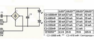
The figure shows a diagram and calculations for 4 LEDs (by the way, there is a typo, it should be C=100nF).
Assembly
The short lead of the LED is the cathode (there is also a designation on the body), the long lead is the anode.
We solder the resistor to the long terminal of the 1st LED.
We cut and bend the leads as shown in the pictures.
We form a square out of them and solder the diode. Don't overheat when soldering, otherwise everything will go to waste!
Now you can check the work. If it doesn’t work, then you probably reversed the polarity, but it won’t burn out (protective diode!), you just don’t leave it like that for long.
Ready-made “light bulbs” can also decorate the interior of a car, house, garden, swimming pool, etc.
There are also online calculators for calculating LEDs and resistors, here.
Driver circuit for CPC9909
Modern pulse drivers for LED lamps have a simple circuit, so you can easily make it even with your own hands. Today, to build drivers, a number of integrated circuits are produced, specifically designed to control high-power LEDs. To simplify the task for lovers of electronic circuits, developers of integrated drivers for LEDs provide typical connection diagrams and calculations of wiring components in the documentation.
General information
The American company Ixys has launched the production of the CPC9909 chip, designed to control LED assemblies and high-brightness LEDs. The driver based on CPC9909 is small in size and does not require large investments. The CPC9909 IC is manufactured in a planar design with 8 pins (SOIC-8) and has a built-in voltage regulator.
Thanks to the presence of a stabilizer, the operating range of the input voltage is 12-550V from a DC source. The minimum voltage drop across LEDs is 10% of the supply voltage. Therefore, the CPC9909 is ideal for connecting high voltage LEDs. The IC works perfectly in the temperature range from -55 to +85°C, which means it is suitable for designing LED lamps and luminaires for outdoor lighting.
Pin assignment
It is worth noting that with the help of CPC9909 you can not only turn on and off a powerful LED, but also control its glow. To learn about all the capabilities of the IC, consider the purpose of its conclusions.
- VIN Designed to supply power voltage.
- CS. Designed to connect an external current sensor (resistor), with which the maximum LED current is set.
- GND. General driver output.
- GATE. Output of the microcircuit. Supplies a modulated signal to the gate of the power transistor.
- P.W.M.D. Low frequency dimming input.
- VDD. Output for supply voltage regulation. In most cases, it is connected via a capacitor to a common wire.
- L.D. Designed to set analog dimming.
- RT. Designed to connect a time setting resistor.
Scheme and its principle of operation
A typical connection of the CPC9909 powered from a 220V network is shown in the figure. The circuit is capable of driving one or more high-power or High Brightness LEDs. The circuit can be easily assembled with your own hands, even at home. The finished driver does not require adjustment, taking into account the correct selection of external elements and compliance with the rules for their installation.
The driver for a 220V LED lamp based on CPC9909 works using the pulse frequency modulation method. This means that the pause time is a constant value (time-off=const). The alternating voltage is rectified by a diode bridge and smoothed by a capacitive filter C1, C2. Then it goes to the VIN input of the microcircuit and starts the process of generating current pulses at the GATE output. The IC's output current drives power transistor Q1. At the moment the transistor is open (pulse time “time-on”), the load current flows through the circuit: “+ diode bridge” – LED – L – Q1 – RS – “-diode bridge”.
During this time, the inductor accumulates energy in order to transfer it to the load during a pause. When the transistor closes, the inductor energy provides load current in the circuit: L – D1 – LED – L. The process is cyclical, resulting in a sawtooth current through the LED. The maximum and minimum value of the saw depends on the inductance of the inductor and the operating frequency. The pulse frequency is determined by the value of the resistance RT. The amplitude of the pulses depends on the resistance of the resistor RS. The LED current is stabilized by comparing the internal reference voltage of the IC with the voltage drop across RS. A fuse and a thermistor protect the circuit from possible emergency conditions.
Calculation of external elements
Frequency setting resistor
The duration of the pause is set using an external resistor RT and is determined using a simplified formula:
tpauses=RT/66000+0.8 (µs).
In turn, the pause time is related to the duty cycle and frequency:
tpauses=(1-D)/f (s), where D is the duty cycle, which is the ratio of the pulse time to the period.
The manufacturer's recommended operating frequency range is 30-120 kHz. Thus, the resistance RT can be found as follows: RT=(tpause-0.8)*66000, where the value of tpause is substituted in microseconds.
Current sensor
The resistance rating RS specifies the amplitude value of the current through the LED and is calculated by the formula: RS=UCS/(ILED+0.5*IL pulse), where UCS is the calibrated reference voltage equal to 0.25V;
ILED – current through the LED;
IL pulse – the value of load current ripple, which should not exceed 30%, that is, 0.3*ILED.
After the conversion, the formula will take the form: RS=0.25/1.15*ILED (Ohm).
The power dissipated by the current sensor is determined by the formula: PS=RS*ILED*D (W).
A resistor with a power reserve of 1.5-2 times is accepted for installation.
Throttle
As is known, the inductor current cannot change abruptly, increasing during the pulse and decreasing during the pause. The radio amateur's task is to select a coil with an inductance that provides a compromise between the quality of the output signal and its dimensions. To do this, remember the ripple level, which should not exceed 30%. Then you will need an inductance with a nominal value:
L=(USLED*tpauses)/ IL pulse, where ULED is the voltage drop across the LED(s), taken from the current-voltage characteristic graph.
Power filter
Two capacitors are installed in the power circuit: C1 – to smooth out the rectified voltage and C2 – to compensate for frequency interference. Since the CPC9909 operates over a wide input voltage range, there is no need for a large electrolytic C1 capacitance. 22 uF will be enough, but more is possible. The capacitance of metal film C2 for a circuit of this type is standard - 0.1 μF. Both capacitors must withstand a voltage of at least 400V.
However, the chip manufacturer insists on installing capacitors C1 and C2 with low equivalent series resistance (ESR) to avoid the negative impact of high-frequency noise that occurs when the driver switches.
Rectifier
The diode bridge is selected based on the maximum forward current and reverse voltage. For operation in a 220V network, its reverse voltage must be at least 600V. The calculated value of the forward current directly depends on the load current and is defined as: IAC=(π*ILED)/2√2, A.
The resulting value must be multiplied by two to increase the reliability of the circuit.
Selecting remaining circuit elements
Capacitor C3 installed in the power supply circuit of the microcircuit should have a capacity of 0.1 µF with a low ESR value, similar to C1 and C2. The unused pins PWMD and LD are also connected to the common wire via C3.
Transistor Q1 and diode D1 operate in pulse mode. Therefore, the choice should be made taking into account their frequency properties. Only elements with a short recovery time will be able to contain the negative impact of transients at the moment of switching at a frequency of about 100 kHz. The maximum current through Q1 and D1 is equal to the amplitude value of the LED current, taking into account the selected duty cycle: IQ1=ID1= D*ILED, A.
The voltage applied to Q1 and D1 is pulsed in nature, but no more than the rectified voltage taking into account the capacitive filter, that is, 280V. The choice of power elements Q1 and D1 should be made with a margin, multiplying the calculated data by two.
The fuse protects the circuit from emergency short circuits and must withstand the maximum load current for a long time, including impulse noise.
IFUSE=5*IAC, A.
Installing an RTH thermistor is necessary to limit the driver inrush current when the filter capacitor is discharged. With its resistance, RTH must protect the diodes of the bridge rectifier from breakdown in the initial seconds of operation.
RTH=(√2*220)/5*IAC, Ohm.
Other options for enabling the CPC9909
Soft start and analogue dimming
If desired, the CPC9909 can provide a soft turn on of the LED as its brightness gradually increases. Soft start is realized using two fixed resistors connected to the LD pin, as shown in the figure. This solution allows you to extend the life of the LED.
Also, the LD pin allows you to implement the analog dimming function. To do this, the 2.2 kOhm resistor is replaced with a variable resistor 5.1 kOhm, thereby smoothly changing the potential at the LD pin.
Pulse dimming
You can control the glow of the LED by applying rectangular pulses to the PWMD (pulse width modulation dimming) pin. To do this, a microcontroller or a pulse generator is used with mandatory separation through an optocoupler.
In addition to the considered driver option for LED lamps, there are similar circuit solutions from other manufacturers: HV9910, HV9961, PT4115, NE555, RCD-24, etc. Each of them has its own strengths and weaknesses, but in general, they successfully cope with the assigned load when assembling with your own hands.
Connecting LED using a simple circuit with a resistor and diode - option 2
Another simple circuit shows how to connect LEDs to 220 V AC voltage is not much more complicated and can also be classified as a simple circuit.
Let's consider the principle of operation. With a positive half-wave, the current flows through resistors 1 and 2, as well as the LED itself. In this case, it is worth remembering that the voltage drop across the LED will be the opposite for a conventional diode - VD1. As soon as the negative half-wave of 220 V “enters” the circuit, the current will flow through a conventional diode and resistors. In this case, the direct voltage drop across VD1 will be opposite to the LED. It's simple.
With a positive half-wave of the mains voltage, current flows through resistors R1, R2 and LED1 (in this case, the forward voltage drop across LED1 is the reverse voltage for diode VD1). With a negative half-wave of the mains voltage, current flows through diode VD1 and resistors R1, R2 (in this case, the forward voltage drop across diode VD1 is the reverse voltage for LED1).
Calculation part of the scheme
Rated mains voltage:
UC.NOM = 220 V
The minimum and maximum network voltage is accepted (experienced data):
UC.MIN = 170 V UC.MAX = 250 V
The LED1 LED having the maximum permissible current is accepted for installation:
ILED1.DOP = 20 mA
Maximum calculated peak current of LED1:
ILED1.AMP.MAX = 0.7*ILED1.ADP = 0.7*20 = 14 mA
Voltage drop across LED1 (experienced data):
ULED1 = 2 V
Minimum and maximum effective voltage on resistors R1, R2:
UR.RMS.MIN = UC.MIN = 170 V UR.RMS.MAX = UC.MAX = 250 V
Calculated equivalent resistance of resistors R1, R2:
REQ.CALC = UR.AMP.MAX/ILED1.AMP.MAX = 350/14 = 25 kOhm
Maximum total power of resistors R1, R2:
PR.MAX = UR.RMS.MAX2/REQ.CALC = 2502/25 = 2500 mW = 2.5 W
Estimated total power of resistors R1, R2:
PR.CALC = PR.MAX/0.7 = 2.5/0.7 = 3.6 W
A parallel connection of two MLT-2 type resistors having a total maximum permissible power is accepted:
PR.ADOP = 2·2 = 4 W
Calculated resistance of each resistor:
RCALC = 2*REQ.CALC = 2*25 = 50 kOhm
The nearest higher standard resistance of each resistor is taken:
R1 = R2 = 51 kOhm
Equivalent resistance of resistors R1, R2:
REKV = R1/2 = 51/2 = 26 kOhm
Maximum total power of resistors R1, R2:
PR.MAX = UR.RMS.MAX2/REQ = 2502/26 = 2400 mW = 2.4 W
Minimum and maximum peak current of LED HL1 and diode VD1:
ILED1.AMP.MIN = IVD1.AMP.MIN = UR.AMP.MIN/REQ = 240/26 = 9.2 mA ILED1.AMP.MAX = IVD1.AMP.MAX = UR.AMP.MAX/REQ = 350/ 26 = 13 mA
Minimum and maximum average current of LED HL1 and diode VD1:
ILED1.AV.MIN = IVD1.AV.MIN = ILED1.RMS.MIN/RF = 3.3/1.1 = 3.0 mA ILED1.AV.MAX = IVD1.AV.MAX = ILED1.RMS.MAX/ CF = 4.8/1.1 = 4.4 mA
Diode reverse voltage VD1:
UVD1.BR = ULED1.PR = 2 V
Design parameters of diode VD1:
UVD1.CALC = UVD1.REV/0.7 = 2/0.7 = 2.9 V IVD1.CALC = UVD1.AMP.MAX/0.7 = 13/0.7 = 19 mA
A VD1 diode of type D9V is accepted, which has the following basic parameters:
UVD1.Add = 30 V IVD1.Add = 20 mA I0.MAX = 250 µA