In general, LED temperature, the cooler the environment, the higher the LED's luminous output. Higher temperatures usually reduce light output. In warmer conditions and at higher currents, the LED temperature increases. The light emission of a DC LED varies depending on its junction temperature. Figure 9 shows the luminous flux of several LEDs as a function of junction temperature. LED temperature is much lower for InGaN LEDs (eg blue, green, white) than for AlGaInP LEDs (eg red and yellow).
| Figure 9. Relative luminous output of red, blue, and phosphor white LEDs as a function of junction temperature. |
| Literature-based data from LumiLeds |
| Data is normalized to 100% at a junction temperature of 25°C LED temperature. |
LED temperature. Current dependence.
Some system manufacturers include a compensation circuit that regulates the current through the LED to maintain a constant light output at varying ambient temperatures. This can cause the LEDs in some systems to burn out during extended periods of high ambient temperatures, which can shorten their lifespan.
Most LED manufacturers publish curves similar to those shown in Figure 9 for their products, and the exact relationships will vary from product to product. It is important to note that many of these plots show light output as a function of junction temperature rather than ambient temperature. An LED operating in an environment of normal room temperature (20°C to 25°C) and at the manufacturer's recommended currents may have much higher junction temperatures, such as 60°C to 80°C. The junction temperature depends on:
- ambient temperature
- current through LED
- amount of coolant inside and around the LED
Typically, the lighting specifier should not be aware of these relationships; The designer of an LED lighting system must include appropriate heat sinks and other compensation mechanisms. The system manufacturer must then provide a range of acceptable operating temperatures within which acceptable performance is expected.
Prolonged heat can significantly reduce the life of many LED systems. Higher ambient temperatures result in higher junction temperatures, which can increase the rate of LED interconnect element degradation, which can result in a permanent reduction in LED light output over a long period of time than at lower temperatures.
Therefore, LED temperature management is one of the most important aspects of optimal LED system performance.
It is common to think of LEDs as "cold" sources in terms of temperature. This is because the spectral output of LEDs for lighting contains no infrared radiation, unlike incandescent bulbs which produce large amounts of infrared radiation (of course, some LEDs for industrial purposes are designed to produce infrared energy, but those are not covered in this post) . LEDs are also often considered "cool" because they generate light through a mechanism different from thermal excitation of a substance such as the tungsten filament in an incandescent light bulb. Although LED lighting systems do not produce a significant amount of radiated heat, LEDs still generate heat in the assembly, which must be dissipated through convection and conduction. Removing heat from the device by using heat sinks and operating LEDs at lower ambient temperatures provides higher light output and longer device life.
The need to provide heat dissipation with LED systems is also important to consider when these systems are installed in applications. There must be sufficient means to remove heat from the system or ventilation to cool heated surfaces by convection. Locating an LED lighting system in an isolated and relatively small space will likely result in rapidly increasing junction temperatures and suboptimal performance.
As high-power LED technology developed, engineers collected data that quantitatively confirmed that excessive heat shortened the lifespan of solid-state lighting (SSL). For example, an LED that lasted 60,000 hours when operating at a junction temperature of 120°C struggled to shine for over 10,000 hours when operating at 150°C. Consequently, thermal management quickly became a key part of the SSL design process.
Designers typically use passive methods to dissipate heat, often not taking the temperature of the LED into account. During normal operation, such methods work well, but may struggle to dissipate all the heat when the SSL is exposed to unusually warm temperatures.
Recently, LED power supply (LED driver) manufacturers have added current limiting capabilities to their devices, allowing engineers to sense the temperature of the LED junction and deflect the wick if things get too hot. Overheat protection extends LED life and minimizes catastrophic failure. Active protection methods also promote the use of smaller heat sinks – saving cost and space – and provide greater control over the maximum operating temperature of a particular product. This article examines how these new thermal management techniques work.
Kelvin Killer
The heat is a byproduct of the electroluminescent processes that allow the LED to light up. Recombinations of holes and electrons in the semiconductor cause some photons to escape from the LED and contribute to overall illumination, but others are reabsorbed into the crystal, generating heat. Tiny vibrations in the LED crystal lattice that occur during operation of the device also increase the temperature. Even though LEDs are highly efficient compared to conventional light sources, 70 to 80 percent of the electricity supplied to a device is still converted to heat rather than light.
Because the LED connection is small, the energy density is high and the temperature rises quickly. It is not uncommon for the junction temperature (TJ) of modern chips to rise to 140°C or higher. Prolonged operation at high temperatures is undesirable as it causes color drift and shortens service life. (See TechZone articles "Thermal Effects on White Chroma LEDs" and "Understanding the Cause of Fading in High-Brightness LEDs").
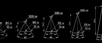
Luminous flux intensity, scattering angle
This characteristic is very important in lighting, especially indoors. Luminous flux intensity is measured in Lumens (Lm). For comparison, a regular 100 W incandescent lamp produces 1000 lm. To simply calculate the voltage of an ice source that will replace an incandescent lamp, you need to divide the voltage of the classic by 8. For example, a 100 W lamp will correspond to an LED with a power of 12 - 12.5 W.
It is important to realize that the source in question has a one-way direction of illumination, while a conventional incandescent lamp scatters light in all directions. LEDs have a point direction. To increase the dispersion angle, special lenses are used in the design. The dispersion angle ranges from 20 to 120˚.
The ratio of efficiency parameters of different light sources given for comparison:
- Incandescent lamp – 10 Lm/W.
- Fluorescent lamp – up to 40 Lm/W.
- LED – up to 140 Lm/W.
LED Temperature Cree, Lumileds, OSRAM and Seoul Semiconductor
LED manufacturers such as Cree, Lumileds, OSRAM and Seoul Semiconductor provide useful information on the effects of temperature on lifespan, gleaned from years of reliability testing. Figure 1 shows, for example, the approximate lifespan of a Lumileds LUXEON C white LED as junction temperature increases. The left axis represents relative brightness. LED indicators consider an LED to have "failed" when its brightness drops below 70 percent of output when using a new one (L70). The LUXEON C is a 118 lm, 120 lm/W (350 mA, 2.75 V) LED, and the graph shows that a 20°C difference can reduce LED life by approximately 60,000 hours (with L70 80,000 hours at TJ= 115°C up to 20,000 hours at TJ=135°C). 1
Figure 1: Effect of junction temperature on the luminosity of LUXEON C LEDs. (LED life is measured at the point where the luminance drops to 70 percent of that when new).
Given the importance of thermal management when designing with LEDs, it is little surprise that there is a lot of design information on the topic available to the design community. LED Thermal Management items in the Digi-Key article library include Understanding LED Internal Thermal Resistance, Thermal Considerations for LED Downlights, and ABCs of LED Thermal Management. Additionally, there are many LED thermal products available on the Digi-Key website.
Passive thermal management techniques have played an important role in cementing LED lighting in the mainstream lighting sector. Design engineers routinely install LEDs and low thermal resistance substrates complemented by heat sinks to remove heat from the device interconnect. However, although this method works satisfactorily, it has a number of disadvantages, including increasing the size of the lighting fixture and adding cost. The heat sink can account for a third of the cost of an SSL device. In addition, as a passive method, mechanical thermal management cannot compensate for large variations in ambient temperature, which may include, for example, an outdoor SSL.
Active Thermal Management
More recently, designers have focused on complementing passive thermal management with active technologies to cater to "extreme" situations where LED lifetimes would otherwise be significantly reduced or the device might even fail catastrophically. The easiest way to protect an LED is to choose an LED driver with overheat protection.
Many modern LED drivers include overheat protection. For example, Analog Devices' recently introduced ADP8140 has this feature. The ADP8140 is a linear regulator that operates from a 3 to 30 V input and provides a constant current of up to 500 mA. If the LED die temperature exceeds 150°C, the ADP8140 turns off the power stage. When the temperature drops below 130°C, the ADP8140 turns off power. If the fault or severe dissipation persists, the sequence is repeated. (Please note that the ADP8140 can also be used with an external heat sensor for enhanced thermal protection.)
The lack of overheat protection, which is based on measuring the temperature of the LED driver rather than the LED connection itself, is a lack of accuracy. Even if the devices are in close proximity, the LED driver can be several degrees warmer than the LED, which can cause stalling when not strictly necessary. Worse, it could be the other way around, causing damage to the LED before the LED driver turns off. The second drawback is that the overheat protection of many LED drivers includes a complete reduction in power when a threshold temperature is reached. This is hardly convenient, especially if the light illuminates a public space. Consequently, engineers tend to set the shutdown function at very high temperatures.
Additionally, many LED drivers automatically restart when the system cools down. If the excessive temperature is the result of a malfunction or an extreme situation, such as an unusually high ambient temperature, the system will likely shut down quickly, resulting in disruptive flicker.
A more subtle technique than simply switching the LED driver when a set temperature is reached is to use a feedback loop that includes a heat sensor located very close to the LED connector. By adding a negative temperature coefficient (NTC) thermistor, which typically has a small package size and a good price/performance ratio, to a lighting circuit it is possible to gradually reduce the LED driving current and therefore reduce power dissipation to the junction temperature limit.
Although decreasing the current reduces the brightness, designers can set a minimum current so that the change in brightness as the NTC sensor is triggered is below the threshold that the consumer can detect. Fortunately, the human eye is not good at detecting brightness changes in high-brightness devices, so there is reasonable flexibility in the balance between controlling temperature and noticeably degrading luminosity. In any case, more subtle than turning off and then turning off.
LED driver manufacturers have made it easier to incorporate an NTC resistor into fixture electronics by adding a dedicated pin to their ICs to accept the resistor input. Duplicated by the thermal return circuit, the NTC thermistor is located as close as possible to the LED connector to improve temperature measurement accuracy. As the temperature increases (above a set point determined by the designer), the resistance of the thermistor decreases, causing a corresponding decrease in the output current that drives the LED. LED driver manufacturers use either pulse width modulation (PWM) or analog dimming to reduce output current. (See TechZone article "How Thermal Runaway Improves the Reliability of LED Lights").
LED drivers typically include current reduction circuits associated with the heat sensor in their products. For example, Semiconductor's CAT4101 is a 1A constant current, heat-cured linear LED driver. The LED driver operates from a 3 – 5.5V input and has a 25V output at up to 1A. The current is reduced by changing the PWM duty cycle once the LED junction temperature exceeds 150°C. Figure 2 shows how the LED drive current (red) changes with the resistance characteristic of the NTC thermistor (blue). 2
Figure 2: Thermal output characteristic of ON Semiconductor's CAT4101 LED driver.
Texas Instruments (TI), among others, also offers a range of LED drivers with thermal cooldown. The LM3424, for example, is a buck/boost (“buck/pulse”) LED driver. The device can operate from a 4.5 to 75 V input, delivering up to 5 A of constant current. The thermal curing feature allows the engineer to program both the breakpoint (the temperature at which current reduction begins) and the gradient of the current reduction slope.
CRI (color rendering index)
For a clearer understanding of this characteristic, it is advisable to familiarize yourself with the principles of color perception by the human eye. White light includes the entire spectrum. When hitting objects around us, only that part of the spectrum that corresponds to the color of the object is reflected. Naturally, a source with a distorted spectrum will distort human color perception.
To determine the degree of fidelity of color reproduction under artificial lighting, the Color Rendering Index (CRI) was developed. The degrees of color rendering index values range from 0 to 100. Index 100 corresponds to sunlight and is a comparative standard.
The full CRI index, at which distortion will be minimal, should not be lower than 90.
