In addition to showing the individual wires, it is also important to show additional details of the electrical circuit on the drawing.
ESKD is a Unified System of Design Documentation.
In particular, it is necessary to connect to the local network of a house with an AVR: Photo - a house with an AVR To develop for free a single-line power supply diagram for a child care facility, private buildings, garages, houses, apartments, kiosks, a multi-storey residential building, a SNT plant, crew cars, you will need an ESKD . Single line diagram designer. Description of work.
Single-line diagrams also display markings and types of electrical equipment, their parameters and class=”aligncenter” width=”1024″ height=”723″[/img] An example of designing a single-line power supply diagram for an industrial enterprise Types of single-line electrical diagrams Depending on what stage To complete the work to create the electrical network of the facility, a single-line diagram is drawn up, its type and intended purpose depend.
If the same elements or devices are not located in all circuits shown single-line, then to the right of the reference designation or below it in square brackets indicate the designations of the circuits in which these elements or devices are located, see. Based on these data, the overall picture is visible and the amount of work can be assessed . If the line is single-phase, no additional markings are required.
It is performed after calculating electrical loads, selecting protective switching devices and cable products. Single-line diagram of the enterprise's power supply. Part 2.
Why is the project needed?
The main purpose of the project is to determine the calculated data on the load characteristics of the network.
The main purpose of a typical electrical project in a private house is to determine the calculated data on the load characteristics of the internal network. In this case, the individual characteristics of the country house or two-story cottage being built are taken into account. According to the legislation of the Russian Federation, a project for connecting electricity to a private house will not be required if the power consumption declared by its owner does not exceed 15 kW (taking into account what is already available).
When submitting an application to Energosbyt for a standard technological connection, it is enough to provide a calculation of the total power consumption and a single-line diagram of the local power supply. However, some regional representatives of energy supply companies indicate in the agreement the need to prepare an electrical design. In this case, it is assumed that it necessarily contains a wiring diagram indicating specific consumers and exact data on the metering device.
Rules for connecting an object to electrical networks
Approval of the project for connecting the facility to electrical networks is carried out after submitting to the Distribution Zone a diagram of the location of electrical appliances and engineering equipment, indicating the total power consumption. This plan is necessary for correctly calculating the required cross-section of the wire strands supplying electrical energy to a house, cottage or site, as well as for selecting electrical equipment. The scheme makes it possible to obtain a permit to connect an object to a power line.
The diagram will be necessary for selecting the cross-section of the electrical wiring cable cores and the parameters of devices and electrical equipment. Its presence is also required to obtain permission to connect to a nearby power line. When calculating energy consumption indicators, it is best to make a certain power reserve, which will allow you to connect additional equipment in the future. The final stage of all these procedures is the conclusion of an agreement with the distribution network division for connection to the main power line. An integral part of the contract are technical conditions.
After work has been carried out by RES employees on the technological connection of the facility to the electricity supply line, the company representative draws up an act, which is the basis for concluding an agreement for the supply of electrical energy. Connection can only be made by employees of the distribution zone, otherwise a large fine may be imposed. For dachas that are part of garden associations, the connection is carried out by the association’s full-time electrician.
Typical power supply project for a private house
Single-line power supply diagram
The power supply project for a private house includes the following mandatory documents:
- Single-line electrical diagram (including distribution panel).
- A house plan indicating the locations of equipment, as well as a diagram of the location of sockets and lighting fixtures.
- Diagram of outlets outside the house, arranged for the purpose of connecting external devices or external outbuildings.
- Calculation data for the grounding loop.
- Plan for organizing a lightning protection device.
- Specification for protective and control equipment (hardware).
- Permits confirming the legality of the work performed by the design organization selected by the contractor.
The last sample working document is required if approval of the project with the energy supply organization is required.
Connection diagram of a single-phase generator to a three-phase network
Let's consider the key points of connecting a single-phase generator to a three-phase network. Recently, this topic was created on the forum, and I decided to give a more detailed answer, as well as discuss this issue on the blog, since many readers do not visit the forum.
Connecting a single-phase generator is relevant for private houses and cottages that want to have an independent power source.
Many luxury houses (cottages) have three-phase input due to high power consumption. Here the question may arise: what kind of generator is needed? A three-phase generator of the required power suggests itself.
Generator for a private home
Is a three-phase generator really necessary?
I will not give a definitive answer to this answer, however, I assume that a single-phase generator will be cheaper than a three-phase one.
I have already told you why three-phase input is bad. The main problem is that it is very difficult to achieve uniform phase distribution. Perhaps the generator does not tolerate operating modes very well when there is constant phase imbalance.
But how can we convert our three-phase shield into a single-phase one?
Everything is very simple. Scheme for automatically connecting a single-phase generator to a three-phase network:
Connection diagram of a single-phase DG to a three-phase network
For this we need only 2 contactors, not counting the auxiliary elements.
In normal mode, consumers are connected to a three-phase network through the KM1 contactor. If the main power is turned off, the generator starts. Starting can be done using the additional contact of the KM1 contactor. Contactor KM1 is turned off, and contactor KM2 is turned on and combines phase 3 into one.
If you do not need automatic starting of the generator, then instead of this ATS you can use, for example, a cam switch for the appropriate power. The connection diagram is similar to KM2. Here we must use either two manual switches or 1 switch, and turn off the supply network with an input circuit breaker.
Which solution is preferable? The choice is yours.
I also advise you to review my old articles:
Requirements for a private home power supply project
Layout plan for a country house
Before preparing a project for a country house, for example, you will first need to obtain specifications for its development from Energosbyt. They spell out the entire list of issues related to the arrangement of electrical wiring. The following items are required to be included:
- Wiring plan for a country house.
- Type and installation location of the distribution panel.
- List of installed equipment, including electricity meter and circuit breakers.
- Breakdown of consumers into groups and other issues.
The specifications also stipulate the power allocated to this facility (no more than 15 kW).
It is necessary to prepare a statement of balance sheet ownership, in which all attention is focused on delimiting the areas of responsibility of the supplying organization and the private consumer. It is drawn up in the form of an agreement concluded between two interested parties and approved after agreement.
The presence of this document allows you to:
- distribute the responsibilities of each party for servicing “their” section of the electrical network;
- have a clear idea of who is responsible for repairs if the supply line (power cable, for example) is damaged;
- connect new facilities to existing and existing electrical networks.
If it is not possible to immediately establish the boundary of responsibility, it is chosen along the perimeter of the outer wall of a private house or land occupied by the owner. With mutual agreement of the parties, other delimitation options are allowed.
How to draw a single line electrical diagram
programs for drawing on a computer ( electrical circuits are not drawn, but drawn! ). But all of them are usually difficult to master if you are not doing it professionally. However, I have found a few that are easy to use for the average person.
Program 1-2-3 scheme
The HAGER software 1-2-3-scheme, Semiolog and hLsys Lume are distributed free of charge. You can and should download it from the official website https://www.hagersystems.ru/software/. Don't look for it at file dumps and garbage collection sites. The program is in Russian.
The “1-2-3 scheme” program allows you to select the electrical panel housing in accordance with the requirements for the degree of protection, equip it with protective and switching modular devices, set a hierarchy for connecting modular devices and automatically generate a single-line diagram of the switchboard .
The program allows you to correctly select the case series and its size, based on the number of modular devices, and label the modular devices in any way. The element base of the 1-2-3-scheme program contains current equipment articles supplied to the Russian market and certified according to Russian and European standards. Using the 1-2-3 diagram, you can competently draw up a specification, create a single-line diagram of the electrical panel and draw its appearance.
It is clear that it is not at all necessary to use the element base of the manufacturer HAGER. The main thing is the result, that is, a single-line diagram, the correct size of the panel body (when there is enough space for all the machines) and, as a bonus, printing labels that can then be pasted on the panel above the machines.
Using the 1-2-3 diagram program, you can easily and with minimal time spend create an electrical circuit for a panel for residential construction. To make better use of the program's capabilities and make better use of time, hager has developed an interface between this new program and the semiolog label program.
To work, you can only use the mouse, develop and print a diagram of the electrical panel and labels indicating the circuit elements for the panel.
An example of a complete board with consumer group markings made in the Semiolog program.
Legrand XL Pro² program
The second program, also from the manufacturer, is XL Pro² from Legrand, which simplifies the design of low-voltage complete devices (LVDs). The program allows switchgear designers to design distribution cabinets and panels of the XL³ series in two ways:
- select Legrand equipment from the proposed list necessary for assembling the cabinet;
- using a single line diagram.
The program will automatically determine the type of complete device, calculate its cost, and arrange the equipment. XL Pro² automatically makes all changes, making the design and calculation of different types of cabinets as simple as possible.
XL Pro is free and available for download by registered Extranet users.
XL PRO³ PROGRAM
XL Pro³ software simplifies the design of low-voltage switchgear (LVD) devices. The program allows NKU designers to design distribution cabinets and panels manufactured by Legrand for currents up to 6300 A using two methods:
- select Legrand equipment from the proposed list necessary for assembling the cabinet;
- using a single line diagram.
The program will automatically determine the type of complete device, calculate its cost, and arrange the equipment. XL Pro³ automatically makes all changes, making the design and calculation of different types of cabinets as simple as possible.
You can download the program on the official website - https://www.legrand.ru/ru/scripts/ru/publigen/content/templates/previewMultiPhoto.asp?P=1715&L=EN
Rapsodie - Switchboard layout
This is the third program in the review for the layout of distribution boards, but now from schneider-electric .
- Rapsodie is designed for the layout of LV cabinets of the Prisma Plus, Pragma and Kaedra series.
- Working in Rapsodie significantly speeds up the cabinet layout process.
- As a result of working with the program, the user can receive: the appearance of the cabinet and a complete assembly specification, as well as a detailed calculation of the cost of the project.
- The program database contains Schneider Electric devices, the user can automatically select additional accessories for them. It is also possible to create a personal catalog of devices that are not in the program database.
- Rapsodie also allows you to display the topology of a single line diagram for the correct selection of distribution devices and mounting accessories.
- The program has a mode for automatically selecting a cell of the desired configuration, taking into account previously specified criteria.
- The program has an attractive and intuitive Russian-language interface; documentation is provided in the form of files in common formats (*.txt, *.xls, *.pdf, *.dxf).
House electrical circuit diagram
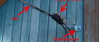
Connecting a SIP to a house
The diagram for connecting a house to a single-phase electrical network takes into account the following mandatory points:
- The cable or the SIP wire that replaces it is connected directly to the switchboard buses through an electric meter.
- After it, each power supply group must be connected through its “own” linear automatic device, pre-calculated based on the current setting.
- The working zero and protective wire of each linear group, unlike the phase conductors, should not be switched.
The neutral core “breaks” like a phase only if there is an RCD in the linear branch, which can be placed both on one group and on their combination. Next, the wires from the group circuit breaker are laid towards the distribution boxes. From them, electrical wiring is routed to end consumers (power sockets and lights with switches).
When preparing an electrical project, the structure of the building must be taken into account, on which the chosen method of laying wires depends.
In houses with a large number of rooms, when drawing up an electrical wiring diagram, the following are taken into account:
- when designing, it is convenient to divide consumers into separate groups: one for each room and for service annexes;
- in the example of a power supply project for a private house, separate branches with a circuit breaker are taken into account, designed to protect a washing machine or oven;
- When preparing design data, the requirement of uniform distribution of loads across groups is observed: due to the significant number of consumers, they often load the network unequally.
Taking into account all these recommendations, you can move on to the practical part of the project.
More information about the wiring diagram
The output of wires from the distribution panel corresponds to the location of consumers in different rooms. Let's take a closer look at typical electrical distribution schemes in a house.
In modern homes, we use various electrical appliances that consume different amounts of electricity. The level of its consumption is expressed in the power of the electrical appliance.
The most powerful consumers in a modern home are electric stoves and sauna heaters, the most economical are light bulbs and small household appliances.
Below are the average power consumption ratings of some of the most commonly used electrical appliances, ranked from most powerful to least powerful (in watts):
- Instantaneous water heater – 5000
- Electric stove – 3000
- Automatic washing machine – 2500
- Welding machine – 2300
- Oven – 2000
- Iron – 1700
- Boiler – 1500
- Vacuum cleaner – 1500
- Heater – 1500
- Microwave oven – 1400
- Electric kettle – 1200
- Fan – 1000
- Refrigerator – 600
- Computer – 500
- TV – 300
- Light bulb – 60
Already from this small list we can see where the main consumers of electricity in our house are concentrated - in the kitchen and in the bathroom-laundry room. Naturally, it is not recommended to turn on all appliances at once, but a switched-on electric stove with a constantly running refrigerator is enough to put a significant load on the network.
It is the nodes from which the wires lead into such rooms that have the most powerful machines.
Electrical network design
External wiring is laid in cable ducts.
Based on the considered diagram for a private house, when preparing a detailed design for an electrical network, you will need to calculate the required number of groups and then distribute consumers. In addition, it is important to decide on how to install the line and calculate the possible load on all devices connected to it.
Choosing a mounting method
Preparatory procedures begin with choosing the method in which the electrical wiring is supposed to be laid. For a private house made of timber, for example, the most suitable is the external laying, in which it stretches along the surface of the walls. If desired, it can be hidden in pre-prepared plastic cable channels.
Hidden installation has to be resorted to in private houses built from brick, foam blocks and similar non-combustible materials.
Total load calculation
At the next stage of work, it is necessary to calculate the total load falling on all consumers connected to the network, which is very important for their subsequent breakdown into groups. To do this, you need to understand the number of devices and the maximum power consumed by each of them. The easiest way to find out this indicator is from the passport that is attached to any of the household products.
By summing up all the indicators and obtaining the total power consumed by all connected loads, it is possible to find out the maximum current in the circuit. To calculate it, you should use the practically derived relationship, according to which a power of 1 kW at a voltage of 220 Volts corresponds to a current of 4.5 Amperes.
Distribution of loads by groups
Distribution of electrical load in the house
The breakdown of consumers is carried out taking into account the fact that the total power of one group of lines of sockets and lighting devices should not exceed 16 Amperes. Based on this requirement, it is necessary to distribute the existing loads into separate groups.
To connect and service powerful loads like an electric furnace, you will need to install a machine with a rating of 25 Amperes in the consumer group.
Distribution into groups is made taking into account their distribution among rooms and depends on the power of a particular load. The PUE recommends separating group lighting lines from power outlets, which is important for buildings with a large number of rooms.
Wiring selection
Before independently laying electrical wiring in a private house, you must carefully calculate the cross-section of its constituent conductors. The durability and fire safety of the entire power supply system depends on the correctness of this procedure.
According to clause 7.1.34 of the PUE, since 2001, only copper cables and wires have been allowed to be used in wooden residential buildings and other buildings.
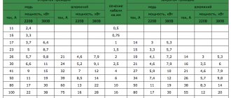
The cross-section of the conductors should be selected taking into account the load found by calculation on all types of group lines. To avoid unnecessary calculations and simplify the choice of this indicator, we usually proceed from the rated current of the group circuit breakers.
The type of wiring installation (closed or open) must also be taken into account, since for conductors laid in different ways, the conditions for heat removal will be different. In both cases, for group lighting lines the cross-section is selected to be no more than 1.5 mm square, and for power (socket) lines - no less than 2.5 square mm. mm.
How to do the wiring in the house with your own hands
Before starting work, read the Electrical Installation Rules (ELD), which outline the basics of working with the equipment.
- Electrical wiring in the house, carried out independently, requires the following conditions:
- free access to metering equipment, distribution boxes, sockets and switches is required.
- they are mounted at a level of 60-150cm from the floor; opening doors should not block access.
- the cable is brought in from above;
- The installation height of sockets varies from 50 to 80 centimeters from the floor. For safety reasons, they cannot be placed less than 50 centimeters from electric and gas stoves, heating radiators, and pipes.
- Power supply is provided from below.
- The number of sockets is determined at the rate of 1 piece per 6 sq.m. This rule does not apply to the kitchen; sockets are installed here according to the number of household appliances.
- To power the bathroom, it is better to provide a separate transformer located outside this room (to reduce the voltage).
- The cable is laid with strict adherence to vertical and horizontal (without bends or diagonals, so as not to damage it during installation and perforation).
- horizontal ones are laid at a distance of 5-10 centimeters from the ceilings and cornices and 15 cm from the ceiling and floor. Vertically located cables are laid at least 10 cm from the edge of the door or window opening.
- The distance to gas pipes should not be less than 40 centimeters;
- The wiring should not come into contact with metal building structures.
- Special boxes are used for wiring and connecting cables. Connections must be securely insulated. It is forbidden to connect copper wires with aluminum ones.