In a previous magazine article (No. 6 for 2022), I explained in detail what short-circuit current is and what significance it has for everyone involved in electrical science. As for practical electrical engineering, in magazine No. 2 for this year, using the example of my apartment and dacha, I measured the real short-circuit current in three ways. Today is the final article in this series of articles. I will tell you what selectivity is and how it is affected by the value of the short circuit current. Let's consider when it is possible and when it is impossible to ensure selectivity and what the consequences of this may be. Get ready - for the completeness of the presentation, I had to analyze in detail some theoretical issues.
In real life, lack of selectivity can lead to very unpleasant consequences. For example, due to a short circuit in an extension cord crushed by a closet, the entire apartment may turn off. Then it depends on the situation. If no one is home, defrosting the refrigerator may cause food spoilage. The consequences may be even worse - if it happens in a private house in winter, due to the pump stopping, freezing of the water in the heating system is quite likely with all the ensuing consequences...
What is selectivity?
In relation to automatic circuit breakers (AB) included in a series circuit, selectivity is the ability to turn off only the emergency line, without turning off the upstream (input) switch.
Instead of the term “selectivity” the concept “selectivity” is sometimes used.
In other words, in a two-stage protection scheme, which is used in the vast majority of cases, when an overcurrent occurs, only the downstream switch feeding the problem line should turn off, and the input switch, through which other lines that are “not to blame” are powered, should continue to work properly work and pass current through itself.
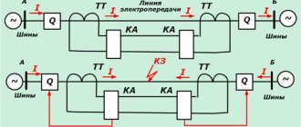
Here is a diagram explaining the selective operation of series-connected circuit breakers.
Diagram to illustrate selective operation of circuit breakers
If an overcurrent occurs in the line that is fed through the circuit breaker AB2, the input AB1 must continue to operate in the on state, feeding the remaining lines (AB3).
As usual, everything is smooth only on paper, since in practice such selectivity depends on several factors:
- on the magnitude (range of values) of the overcurrent that arose as a result of an emergency situation;
- on the ratio of the denominations of the superior and inferior AB;
- on the shutdown characteristics (time-current characteristics) of electromagnetic releases AB (B, C, D).
In addition, it should be taken into account that in practice we are not dealing with GOST graphs and standards, but with real devices that may have a spread of parameters in a certain range.
What is overcurrent?
Overcurrent, as is known, is any current that exceeds the rated current. Its maximum value in practice can be considered equal to the short-circuit current.
Typically, the rated current of a circuit is considered to be the rated current of the “lower” circuit breaker that limits the current in this circuit. Of course, if the calculation of the circuit is carried out correctly and the circuit breaker is the weak link that will break the circuit during overcurrent.
All overcurrent values are conventionally divided into two parts - overload current and short circuit current . This division is due to the fact that each of these currents is “responsible” for its own release inside the circuit breaker. Overload current is usually called the current that triggers the thermal release (bimetallic plate), which operates relatively inertly. Short circuit current refers to those overcurrent values at which circuit protection is provided by an electromagnetic (EM) release that operates much faster than a thermal release.
It is necessary to distinguish three concepts - the phenomenon of short circuit, short-circuit current as a measured parameter of the electrical network at a given point, and short-circuit current as the area of operation of the circuit breaker, at which the electromagnetic release is triggered. Oh, these liberties in terminology!
Conclusions and useful video on the topic
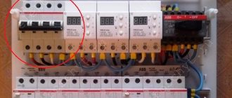
Problems with the operation of circuit breakers and their elimination:
Drawing a selectivity map using a special program:
Reliable, safe use of electrical wiring is impossible without taking into account the selectivity of the machines. Knowing about the main points of creating selective protection, you can competently select equipment for your technical project.
Are you professionally engaged in electrical installation work and want to supplement the material presented above? Or noticed an inconsistency or error in this article? Or maybe you want to ask our experts a question? Please write your comments in the block below.
Reliable and safe operation of electrical networks is ensured in various ways, among which the selectivity of circuit breakers plays an important role. It is a special relay protection function that can selectively detect a faulty section or element in the overall system and turn off only that one. Thus, emergency situations are prevented, and the level of protection becomes significantly higher.
What are time-current characteristics?
Hoping that the reader is prepared, I will be brief and talk only about what relates to the topic of the article. The letters B, C and D are the main characteristics of the electromagnetic release. The letter indicates the range of instantaneous tripping currents. At the beginning of this range, the EM release should not operate , within the range it may operate , and at an overcurrent equal to the upper end of the range (or more), it should operate . The range limits can be illustrated using simplified graphs for three AVs with the same rated current of 10 A, but with different shutdown characteristics:
Graphs for one rated current and different tripping characteristics
The thermal release graph, shown as a smooth thick line, is the same for all three circuit breakers. But the ranges of instantaneous tripping currents (shaded in blue) are different.
With an overcurrent of up to 11.3 A, our three switches should never turn off. As the current increases, the turn-off time decreases down to seconds, and when operating in the so-called short-circuit current zone, the turn-off time can be tens or even a few milliseconds. All currents that exceed the marked ranges shall result in instantaneous tripping.
Details about the time-current characteristics of circuit breakers can be found in GOST IEC 60898-1-2020.
Main functions
The key objectives of selective protection are to ensure uninterrupted functioning of the electrical system and prevent mechanisms from burning out when threats arise. The only condition for the correct operation of this type of protection is the consistency of the protective units with each other.
As soon as an emergency occurs, the damaged area is instantly identified and switched off using selective protection. At the same time, the working places continue to work, and the disabled ones do not interfere with them in any way. Selectivity significantly reduces the load on electrical installations.
The basic principle of arranging this type of protection lies in the equipment of circuit breakers with a rated current that is less than that of the device at the input. In total, they can exceed the nominal value of the group machine, but individually - never. For example, when installing a 50 A input device, the next device should not have a rating higher than 40 A. The unit located as close as possible to the emergency site will always operate first.
Thus, the main functions of selective protection include:
- ensuring the safety of electrical devices and workers;
- quick identification and shutdown of the area of the electrical system where the breakdown occurred (at the same time, the working areas do not stop functioning);
- reduction of negative consequences for the working parts of electrical mechanisms;
- reducing the load on component mechanisms, preventing breakdowns in the faulty area;
- guarantee of continuous work process and constant high-level power supply.
- support for optimal operation of a particular installation.
Selectivity and supercurrent - what is the connection?
Selectivity can be complete when the higher-level circuit breaker does not turn off at any short-circuit current, which is limited by the breaking capacity of the lower-level circuit breaker.
In practice, when using modular circuit breakers, it is possible to achieve only partial selectivity, which is ensured only in a certain range of overcurrent values. The upper limit of the partial selectivity zone is called the limiting selectivity current Is. Partial current selectivity will be ensured if the overcurrent is not greater than the selectivity current Is.
The maximum overcurrent at a specific point in the circuit is equal to the short-circuit current Is . Therefore, in practice, we can assume that complete selectivity of operation of series-connected AVs is ensured at Is ≤ Is , and partial selectivity at Is > Is .
When selectivity is ensured, then in the event of an overcurrent, nothing terrible will happen - the machine of the problematic line will simply work, and the remaining lines will continue to work as if nothing had happened.
In the zone of overload currents, we can talk about time-current selectivity, since selectivity is affected by both the level of overcurrent and the duration of its action. But in the zone of short-circuit currents there is only current selectivity, since the response time of electromagnetic releases of all characteristics is the same.
Official definitions on the topic of selectivity can be read in GOST R 50030.2-2010 (in particular, clause 2.17).
Example of ensuring selectivity
For example, let’s see how the time-current characteristics of two AVs will look on one graph - with a rated current of 10 A and characteristic “B” (B10, we talked about it above) and with a rated current of 25 A and characteristic “C” (C25) . If these circuit breakers are connected in series, the selectivity zone will be located between their instantaneous tripping current ranges. That is, selectivity and normal operation of the circuit will be ensured at overcurrents from 50 to 125 A:
Formation of a selectivity zone between time-current characteristics B10 and C25
Thanks to the graphical representation of the VTX, we see that the maximum selectivity current is equal to the minimum instantaneous tripping current - 125 A. If the expected short-circuit current (the maximum possible overcurrent) at the fault point is less than 125 A, we can talk about complete selectivity - at any overcurrent from 50 up to 125 A, the downstream circuit breaker (B10) will turn off instantly, and the upstream one (C25) will remain on. Everything is clear here.
But what will happen at overcurrents of less than 50 A? The only thing that will change here is that the shutdown time may be longer - this is clear from the schedule. However, such overcurrents are rare in practice, and a short-circuit current of 50 A indicates that the wiring needs to be changed - it cannot provide normal power supply and fire safety.
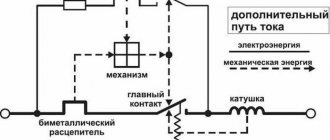
A logical question may arise here - why does the C25 switch need an electromagnetic release if it does not function at currents less than 125 A?
The answer can be given by looking at this diagram:
So far we have talked about the short-circuit current at the end of the cable line, in the load area. This current is designated as Iкз2. But in the electrical panel where both circuit breakers are installed, the short-circuit current, designated as Iкз1, can be significantly higher. In our case, in the panel it can be more than 200 A. And if a short circuit occurs in the panel after the input AB (and this happens mainly due to the human factor), it will turn off instantly.
Therefore, if you arrange a short circuit in the panel immediately after the group automatic machine AB2, do not be surprised that both automatic machines are knocked out - after all, the selectivity condition is not met.
By the way, many bright minds studying the topic of selectivity come up with a brilliant idea - to install a machine with characteristic “D” at the input. Yes, the selectivity will be excellent - about the same as if you install a switch at the input. Indeed, in the case of low short-circuit current, such a machine will be useless.
Types of selective connection schemes
In addition to absolute and relative selectivity, there are 7 more types of selective protection:
- zone;
- time-current;
- energy;
- temporary;
- full;
- partial;
- current
To ensure the required selectivity of auto-protection of electrical networks with circuit breakers, different methods are used. But in any case, it is important to install the switch correctly, following the selected diagram and installation rules.
Type #1 - full and partial protection
Full protection means that if a pair of circuit breakers are connected in series, the appearance of overcurrents causes the one located near the fault zone to shut down.
Partial protection operates on the same principle as full protection, but only after the current reaches the set threshold.
If selectivity is ensured to the smaller of the current values of two AVs, there is reason to talk about complete selectivity between them. In this case, the maximum value of the estimated short-circuit current of the installation under any circumstances will be equal to or less than the current value of the two circuit breakers.
Type #2 - current selectivity type
The main indicator of current selectivity is the maximum current mark. From the object to the input, the values are arranged in ascending order. The operation of this selectivity of protection is based on the same basis as that of time selectivity.
The only difference is that the shutter speed is based on the current value - as the short-circuit point approaches the input, the short-circuit current readings increase. The shutdown time may be the same.
The zone damaged due to a short circuit is determined by the trip setting for different current values. Full selectivity can only be achieved in conditions where the short-circuit current is low, and in the gap between two circuit breakers there is equipment with considerable electrical resistance. In this situation, the short-circuit currents will differ significantly.
This type of selectivity is used mainly in final switchboards. This combines a rated current of insignificant value and a short-circuit current with a high impedance of the connecting cables.
Read also: Height of sconces on the stairs
This selectivity option is economical, simple and works instantly. However, often the indicated selectivity may be partial because the highest current is usually small.
When the values of Isd1 and Isd2 are the same or extremely close, then Is - the maximum selectivity current is equal to Isd2. If these values are much different, Is = Isd1.
The condition for ensuring current selectivity is the following inequalities: Ir1/Ir2 > 2 and Isd1/Isd2 > 2. In this case, the maximum selectivity is Is = Isd1.
Disadvantages include the rapid increase in the level of protection settings against high currents. It is impossible to quickly disconnect a damaged chain if one of the machines turns out to be faulty.
When calculating current protection settings, it is necessary to take into account the actual currents passing through circuit breakers operating in automatic mode.
Type #3 - time and time-current option
When there are a number of circuit breakers in a circuit that have identical current characteristics, but different holding times, then in the event of a malfunction they insure each other. The one that is located in close proximity to the damage site will work immediately, the next one will work after some time, etc.
In the case of time-current selectivity, protective devices react not only to the current, but also to the duration of the reaction. At a certain current value, after some delay time, the protection is triggered, the distance from which to the fault location is less. The working part of the installation does not turn off.
The combination of current and time selectivity increases tripping efficiency. When Isc B View #4 - energy selectivity of machines
With energy selectivity, shutdowns occur inside the machine body. The duration of the process is so short that the short-circuit current does not have time to approach its limit value.
The time-current protection system is considered complex. This involves not only the reaction to the current, but also the time during which this occurs.
As the current increases, the response time of the machine decreases. The basis for this type of selectivity is the regulation of protection in such a way that, on the part of the protected object, it operates faster at all threshold current values, compared to the circuit breaker at the input.
Type #5 - zone defense scheme
The zone method is complex and expensive, so it is used mainly in industry. As soon as the current thresholds reach their maximum, data is sent to the control center and the selected machine is triggered. An electrical network with this type of selectivity includes special electronic releases.
When a violation is detected, a signal is sent from the switch located below to the device located above. The first machine must respond within a second. If it does not react, the second one is triggered.
Comparing this type of selectivity with time selectivity, you can see that the response time in this case is much lower - sometimes hundreds of milliseconds. Both the percentage of intervention in the system and the percentage of its damage are reduced. Thermal and dynamic influences on parts of the installation are reduced. The number of selectivity levels is increasing.
In the case of zone selectivity, the protection located on the power source side is triggered, if we take the short-circuit location as the starting point. Until the machine is triggered, control is exercised to ensure that the protective device on the loaded side does not give a similar signal.
But such selectivity requires the presence of an additional power source. Therefore, the rational use of this type of selectivity is in systems with high short-circuit current parameters and a significant current. These are switching and distribution devices located on the load side of generators and transformers.
Selectivity graphs
The VTX graphs that I provided to clearly demonstrate the selectivity zone relate only to two specific circuit breakers - C25 and B10. I propose to go further and build universal graphs that can be used to determine selectivity zones for any pairs of machines.
Graphs to determine the selectivity zone
The orange zone on the graphs is the range of instantaneous tripping currents for characteristic “C”, the blue zone is for characteristic “B”. The chart is easy to use. For example, we choose the pair C25-B10 that we already know. On the graphs, red segments indicate their “unsteady zones”, up to which they should not operate during a short circuit, and after which they should . Between these zones we draw dotted lines, which will mark the boundary of the selectivity zone.
The graph is universal - it can be used to graphically determine the selectivity zone of a pair of machines of any denomination.
Principles for selecting RCDs based on their response time
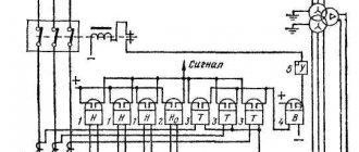
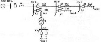
We will demonstrate the implementation of this procedure using the following diagram.
RCD selection scheme based on response time
For example, 25A is used as the current setting for all machines, and the temporary setting for different protective elements is different.
If a fault occurs in a consumer that receives power through the 3rd circuit breaker, then the current from the short circuit will trigger:
- machine in problem area No. 3;
- on distribution board No. 2;
- at main switchboard No. 3.
The minimum time setting is set on machine No. 3, it is equal to 0.1 sec. This machine will work first and localize the breakdown area. Switches numbered 1 and 2 will remain on and provide power to zones 4 and 5.
If machine No. 3 for some reason does not work after 0.1 seconds, current cutoff will have to be performed by machine No. 2, which is responsible for protecting the distribution panel. This will happen in 0.5 seconds, and users of not only zone 3, but also zones 4 and 5 will be de-energized.
If neither 3 nor 2 circuit breakers work, then protection is provided by circuit breaker No. 1 on the main distribution board. The current will be cut off after 1 second. In this case, zones 3, 4 and 5, which are powered by main switchboard No. 2, will be disabled, as well as users connected to the main switchboard No. 1.
Selectivity tables
I could construct a more detailed selectivity graph taking into account the range of denominations produced by AB. But most manufacturers have already taken care of this issue and have provided selectivity tables on their websites. These tables are more convenient than graphs due to the abundance of information.
The selectivity tables list all models and ratings of manufactured circuit breakers. Knowing the rated currents and tripping characteristics, it is possible to determine the selectivity limit current. You can also solve the inverse problem - knowing the short-circuit current in the electrical panel and the short-circuit current at the end of the protected line, select from the tables the models of the input and group circuit breakers that can provide selectivity in this case.
Main tasks of selective protection
As for a person, his perception of the world around him, the choice of information, as well as its memorization are selective.
What is selectivity in electrical engineering, and why is it needed?
The tasks of electrical selective protection include:
- guaranteeing the safety of equipment and operating personnel;
- instantly identifying the location of the fault and disconnecting only the faulty section;
- reducing the negative effects of the accident on other components and parts of electrical appliances;
- minimizing damage to the faulty area;
- guaranteeing maximum continuity of operation of the electrical system;
- achieving ease of operation of electrical equipment.
conclusions
It is worth remembering that if the issue of selectivity between modular AVs is acute, the following conditions must be met:
- The short-circuit currents in the panel and in the load area must be known;
- the rated currents of series-connected circuit breakers must differ by at least 2.5 times;
- The “current distance” between the extreme points of the instantaneous tripping ranges must be such that the currents differ by at least 2 times.
In practice, it is not always possible to ensure selectivity during short circuits using modular AVs. This pessimism is justified for several good reasons:
- high short-circuit current exceeding the maximum selectivity current (Is>Is);
- limiting the nominal value of the input AV at the request of the energy supply organization;
- limiting the ratings of group circuit breakers based on the cable cross-section and load power.
At industrial enterprises, where the lack of selectivity can lead to a shutdown of the technological process and large material losses, automatic circuit breakers of category “B” are used (do not confuse with the shutdown characteristic “B”!) or with electronic releases. As a result, in the zone of short circuit currents it becomes possible to ensure complete selectivity.
Basic rules for constructing a selectivity map
- All protection settings must be reduced to the same voltage
- Choose the construction scale correctly so that all boundary points are visible. To fulfill this condition, a logarithmic scale is often used.
- The selectivity map displays not only the protective characteristics, but also the boundary (minimum and maximum) short circuit currents at the design points of the circuit.
Advice
Avoid using colors to differentiate curves because most modern designs are printed on black and white laser printers. Better use geometric marks (circles, triangles, crosses, etc.)
Next time we will build a selectivity map to protect a 10/0.4 kV power transformer and its adjacent protections using the Greedis-KS program