Name and terminology in relation to optical sensors
As the name implies, these sensors use optics, which means light radiation of various ranges. That is, a sensor that responds to light. And, of course, some kind of signal indicates that light has been detected. In English terminology, optical sensors are often called PhotoCell Sensor , or Light Sensor , which means photosensor, or light sensor.
In our country, too, in addition to the common “ optical ” one, the same devices are called photosensors , or photoelectric sensors .
The simplest and most common version of such a sensor is a light sensor, which discretely reacts to the level of illumination and issues a signal to turn on the lighting at dusk (main application)
A great variety of photo sensors have been invented, and in my article I will try to popularize and classify this variety.
Types of devices
You can find photoelectric sensors of analog or discrete types.
- With analogues, the output signal can vary in proportion to the available lighting level. Typically, such devices are used to create automatically controlled lighting elements.
- Discrete devices change the value to the diametrically opposite indicator when a certain level of illumination is reached. They can perform all sorts of tasks on an existing production line and are widely used in industry.
An optical non-contact device regulates changes in the incoming light flux in the work area and can operate at a great distance, responding to changes in objects, their absence or presence. The design of this device has two parts that are responsible for proper functioning - a receiver and an emitter. They can be located either in one suitable housing or in different ones.
Operation of optical sensors
Activation. This is the keyword that should be used when describing the operation of any sensors. In our case, activation (or deactivation, but more on that later) occurs when the light entering the sensor input has sufficient intensity.
The operating logic is such that when light enters the sensor unimpeded, it will be activated. And when this light is interrupted by a barrier (a person, a workpiece, a machine part), the sensor is deactivated.
Attention! Don't be confused! Active does not mean at all that its contacts are closed and there is voltage at the output! The operation of the light detection circuit and the output switch may vary! It is possible that the light is interrupted, and this serves as a signal of activity. It all depends on the specific application.
Optical sensors (as well as inductive proximity sensors) are non-contact, that is, there is no mechanical contact with the observed object (activator). Unlike (for example) limit switches and pressure sensors.
In most cases, to increase noise immunity, light is used not from the usual spectrum, but from a laser light source (usually red). Such a source is easy to manufacture; the radiation is easily focused into a thin beam. And due to the fact that the radiation is in the visible part of the range, the position of the sensor is easy to adjust in space.
And here is one of the rare sensors with an ordinary incandescent light bulb, which I found during his lifetime. The emitter is a 6 V incandescent light bulb with a lens. The receiving element is a photodiode. Next is an amplifier and a Schmitt trigger on transistors.
Optical sensor with incandescent bulb and lens. A spot of light is visible below
This sensor is from a 1980 production line purchased with petrodollars from Switzerland.
Modern sensors respond only to “their” part of the spectrum, which allows them to operate accurately in conditions of interference and poor visibility.
Interference may be sunlight or artificial lighting, dust, smoke.
In case of poor care, ordinary dust and dirt can become a hindrance:
Dirty optical sensor, sensitivity adjustment knob on the side, emitting part looking down
On optical sensors, in most cases there is a “Dark On / Light On” switch. What does it mean? It inverts the logic of operation. With “Dark On,” the sensor is activated when no light reaches its input, that is, there is darkness at the input. When light hits, the sensor is deactivated, that is, its output returns to normal. In “Light On” mode, the sensor is activated when its input is illuminated.
There are models where there is a timer - the output signal appears some time after activation (triggering).
Since the sensor contains a threshold element, it needs to be triggered clearly. In this case, the property of hysteresis is used, which reduces bounce (frequent changes in the signal in the “unsteady” zone). To facilitate setup, manufacturers now install in the sensor housing not only an activation indicator, but also an indicator of a stable signal level. If it is lit, it indicates that detection is stable, with sufficient signal strength, and not at the edge of the sensitivity range.
Photoelectric sensors. Photosensors. Device, types and types of photo sensors.
Photoelectric sensors (photosensors) are used in automation to convert various non-electrical quantities into an electrical signal: mechanical movements, speed of dimensions of moving parts, temperature, illumination, transparency of a liquid or gaseous medium, etc.
Based on the principle of information encoding, photo sensors can be divided into two groups: with amplitude modulation of the light flux and with time or frequency modulation. For sensors with amplitude modulation, the value of the photocurrent is proportional to the luminous flux, which depends on the controlled (controlled) non-electric quantity. For sensors with time or frequency modulation, the photocurrent changes discretely due to the complete or partial interruption of the light flux from the influence of a non-electric quantity. Information about the controlled (monitored) parameter is encoded in these sensors in the form of the number, frequency or duration of photocurrent pulses.
A photo sensor generally consists of a photoelectric sensing element (photocell) of a light source and an optical system. In some cases, photo sensors use light radiation from the control object and do not contain a light source (sensors for an astronomical compass, temperature, illumination, etc.). Some sensors may not contain an optical system to simplify their design.
In most photo sensors, the conversion of an input non-electrical quantity into an electrical signal is carried out in two stages: first, it is converted into a change in one of the parameters of the light flux (luminous intensity, illumination, spectral composition, etc.), and then this change is converted by a photocell into an electrical quantity (photocurrent, voltage drop, photo-EMF, etc.).
All photo sensors can be divided into several types based on the nature of the formation of the effect of the light flux on the photocell.
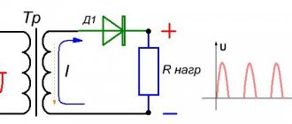
1. Photosensors in which the luminous flux changes due to movement of the controlled (monitored) object or changes in the size of the object (Fig. 2-7). In these sensors, the light source 1 and the optical system (condenser) 2 form a parallel and uniform light flux F. In this light flux there is placed a part Z, the dimensions of which need to be controlled, or a shutter 4, mechanically connected to the op-amp and blocking part of the light flux. When the size of the part d changes or when the shutter x moves, the amount of light (radiant energy) falling on the photocell 5 changes. To increase sensitivity, the light flux F1, containing information about the dimensions of the part (or about the movement of the object), is collected by the optical system 6 and focused on the photosensitive photocell surface. Photoelectric micrometer sensors, length sensors, area sensors, deformation sensors, etc. work on this principle. The operation of discrete photo sensors, such as photoelectric sensors (converters) “angle-code”, rotation speed sensors, photo-reading sensors from punched paper tapes, etc. is based on this principle , punched cards, photo sensors for the end of the magnetic tape, sensors for the size of the loop of the magnetic tape located in the pocket of the tape drive mechanism of the magnetic tape storage device, etc.
2. Photosensors in which the light flux hits the photo element after reflection from the control (control) object (Fig. 2-8). In these photosensors, the light source 1 and the optical system 2 form a narrow light beam, which, after reflection from the object 3, enters through the collecting and focusing optical system 4 onto the photocell 5. The amount of reflected light hitting the photocell depends on the reflectivity of the object surface (the purity of the processing , shine, presence of areas covered with paint, etc.). Such photo sensors are used in reading machines capable of automatically reading and encoding information from text and graphic documents, in surface cleanliness meters, photoelectric reflectometers, hygrometers, etc.
3. Photosensors in which the luminous flux is created by the control (monitoring) object (Fig. 2-9). In these photosensors, the light flux emitted by the op-amp contains information about the controlled (controlled) parameter of the object 1. The optical system 2 collects and focuses the light flux onto the photosensitive surface of the photocell Z. Similar photosensors are used in photoelectric temperature meters, radiant energy dosimeters, devices for emission spectral analysis.
Photocells with external, valve and internal photoelectric effects are used as sensitive elements in photosensors.
Photocells with external photoeffect
These are vacuum and gas-filled photocells; photomultipliers have a high linearity of light characteristics (dependence of the photocurrent on the luminous flux) and high temperature stability of characteristics. However, they also have a number of significant disadvantages that limit their use in automatic control and monitoring devices: the need for increased supply voltage (hundreds and thousands of volts); fragility of the glass container and the possibility of deformation of the electrodes under mechanical stress; aging and fatigue of photocells (reduced sensitivity in strong light conditions).
Valve photocells
They are distinguished by their high reliability and durability, do not require a power source, and are light in weight and dimensions. Their disadvantages are: strong influence of ambient temperature; fatigue and high inertia, limiting the use at a frequency of interruption of the light flux of several tens of hertz.
Photodiodes and phototriodes
widely used in various types of photo sensors. They have a linear light characteristic, high sensitivity, low inertia (the frequency of interruption of the light flux can be up to several kilohertz), and small dimensions. Depending on the switching circuit, valve and photodiode (phototriode) modes of operation of photodiodes and phototriodes are distinguished.
In gate mode, the photodiode is a photocurrent generator and does not require a power source. A phototriode in valve mode can be considered as a combined electronic device - a photodiode (p-p junction of the base-emitter circuit) and the triode itself, which amplifies the photocurrent that arises in the base-emitter circuit under the influence of a light flux. The base of the phototriode in this mode is short-circuited with the emitter. In gate mode, photodiodes and phototriodes are used in photosensors with a proportional light characteristic (measuring dimensions, displacements, temperature, etc.).
In photodiode mode, an external voltage must be applied to the photodiode in the reverse blocking direction. For phototriodes in phototriode mode, a bias voltage from an external source is supplied to the base circuit. The photodiode (phototriode) mode of switching on photodiodes (phototriodes) is used mainly in photosensors with a discrete light characteristic (photoreaders from punched tapes, punched cards, photoelectric angle-to-code converters, reading machines, etc.). In photodiode (phototriode) mode, photodiodes and phototriodes have greater sensitivity than in valve mode (the output signal in this mode is voltage).
Photoresistors
Along with photodiodes and phototriodes, they are widely used, mainly in photosensors with discrete light characteristics. The advantages of photoresistors are high sensitivity, stability of parameters, greater reliability and durability, the ability to operate on both direct and alternating current, and small dimensions. Their disadvantages include large inertia, strong influence of ambient temperature, nonlinearity of the light characteristics, and a large spread of parameters among photoresistors of the same batch.
The op-amp itself is used as a source of light energy in some photo sensors (when measuring temperature, illumination, etc.). Most photo sensors
needs an artificial source of light flux. Inexpensive and easy-to-use ones are most widely used as such sources in photo sensors.
incandescent lamps. In order to increase their reliability and durability, working
the voltage is reduced by 20-30% compared to the nominal.
To work in the infrared region of the spectrum, special emitters are used in the form of pins made of heat-resistant semiconductor materials. Less common in photo sensors are gas-discharge lamps. They have high light output and consume 2-3 times less energy than incandescent lamps. However, the range of these lamps is limited; their dimensions are larger than incandescent lamps.
Optical systems of photo sensors serve to redistribute the radiant energy flux in space in order to increase the efficiency of the influence of control (monitoring) objects on the parameters of the radiant flux. The functions of optical systems of photo sensors are very diverse and require the use of a wide variety of lenses, mirrors, prisms, diaphragms, diffraction gratings, light filters, etc.
In order to increase noise immunity, some photo sensors contain a pre-amplifier of the photocell output signal. Microelectronic operational amplifiers are currently mainly used for this purpose.
In general, when evaluating photo sensors, one should note their great versatility, the absence of feedback on the control (control) object - non-contact. The disadvantages of photo sensors are sensitivity to vibrations, shocks, poor performance in dusty, gassy and humid environments, and interference from general lighting fixtures.
Differences in the way light is transmitted
These are the main differences by which discrete optical sensors are classified. The difference is in the method of “delivery” of light to the input optical element of the sensor.
The most reliable -
With separate receiver and transmitter
Sales managers call such sensors barrier, or beam-intersecting. Although, I think this is incorrect - all discrete sensors work with the beam intersecting with some kind of barrier.
Optical transmitter-receiver type sensor with separate parts
This is the most reliable type of sensor in terms of range and noise immunity. In all other sensors, the transmitter and receiver of radiation are located in the same housing, but in this one they can be separated by tens of meters.
That is, the transmitter is installed in one place, and power is supplied to it. It emits without performing any other functions and without settings. And the receiver is installed at a distance, and sensitivity and other parameters and functions can be adjusted there.
The emitter and receiver must be from the same pair (set), although they can be purchased separately. Transmitters and receivers from different companies do not fit together (but this is not certain).
Such sensors are used in production where long distances need to be monitored. Also - in safety circuits, in security systems and where the air may be polluted (dust, gas).
There is also an option for domestic use - I saw barrier photosensors in an elevator:
Optical sensor in elevator
As long as some clothing or part of the body crosses the path of the sensor beam, no one will go anywhere.
With reflector (reflective)
These sensors combine a source (transmitter) and a radiation receiver in one housing.
Reflex optical sensor with retroreflector
The light is reflected from the reflector and comes back. Therefore, some manufacturers call such sensors retroreflective (reverse reflection).
Optical sensor with reflection from a reflector
By the way, the photo shows the Dark / Light On switch, sensitivity control, and stability and response indicators.
And here is a good photo, the optics of the transmitter and receiver are visible:
Reflex sensor on the optics side, mounted on a bracket
Such a sensor is necessarily a system. For example, a conveyor, and a sensor-reflector system controls the passage of a workpiece:
Reflex sensor on one side of the conveyor
A reflector may also be called a reflector, retroreflector or reflector:
Reflector for optical sensor on the other side of the conveyor
The maximum working distance at which stable operation is ensured is from 5 to 10 m for different models. Theoretically, more is possible, but in practice it is very difficult to ensure stable operation - the slightest shift of the beam due to vibration or weakening of the light due to dust, and that’s all.
The sensor is contaminated with dust, the maximum range in this case drops by about 30%
Reflex type sensors are most often used in production.
Diffuse
This type of sensor is reflective from the object.
Diffuse optical sensor with reflection from the object
It has the shortest range (up to half a meter), but it has an important property - when properly configured, it detects the appearance of objects in the coverage area. After all, you can’t put reflectors on every box or bottle!
The object can be on the axis of action of the sensor, at a distance. As you approach, the sensor, like a threshold element, is triggered.
In the simplest case, there is only one adjustment - sensitivity.
Cool sensors have several buttons or controls, and can be programmed and trained:
Diffuse sensor with training and many settings
In this article you can familiarize yourself with the nomenclature and technical characteristics of the main types of photoelectric sensors produced by the German company SICK AG.
The development of increasingly sophisticated “intelligent” sensors and sensor systems for the automation of production and technological processes is the main focus of SICK AG. A small company founded in 1946, over the course of its existence, has grown into a large international concern. The constant introduction of the latest technologies and a thoughtful pricing policy provide SICK with a leading position in the world market. In particular, in the market for photoelectric and optical sensors with advanced capabilities (distance sensors, color and contrast sensors, fluorescent mark sensors, etc.), SICK AG ranks first in the world in terms of sales of these product types. As with the rest of the company's products, SICK photoelectric sensors use the latest advances in science, technology and technology, which allows us to achieve an optimal price/performance ratio. The authors of many of these developments are company specialists. It is worth noting that it spends approximately 9% of its annual turnover on scientific development. Photoelectric sensors can be used in virtually all industries as proximity switches for counting, detection, positioning and other tasks on any process line. The company SICK AG began its activities with photovoltaics and the following classes can be distinguished in the range of manufactured products:
- photoelectric sensors with reflection from an object (proximity photoelectric switches);
- photoelectric sensors with reflection from a reflector (reflex photoelectric switches);
- through-beam photoelectric switches;
- photoelectric sensors with foreground suppression;
- photoelectric sensors with background suppression (proximity photoelectric switches with background suppression);
- photoelectric sensors with fiber-optic cable (fiber-optic photoelectric switches).
There are quite a lot of companies on the market that produce this type of product. At first glance, the products of one company differ slightly from the products of another. However, modern photoelectric sensors are complex devices. In them, engineers have embodied modern technologies and the latest achievements of science. Let us dwell on the class of photoelectric sensors that operate on the principle of reflection from an object (see Fig. 1). These are the most inexpensive photoelectric sensors, the sensitivity of which is changed using a potentiometer. Light objects reflect more light than dark objects and, in addition, a light object can be detected at a greater distance. To achieve similar results with a dark object, the sensitivity of the sensor is increased using a rotary potentiometer.
Rice. 1. The principle of operation of the sensor with reflection from the object
It should be noted that these sensors have a certain problem in recognizing dark objects against a light background. At the same time, these devices are an ideal choice for detecting light objects against a dark background. It should also be mentioned that there are certain problems with detecting mirrored objects with complex surface geometry, as well as the possibility of negative influence of external lighting sources. The main advantages of this type of sensor are the following: there is no need for a reflector, low cost, and the ability to reliably detect light objects on a black background. Disadvantages include the lack of foreground and background suppression and problems with identifying black objects on a light background. The next type of sensor is photoelectric sensors, which operate on the beam-crossing principle. In this method, the transmitter and receiver are separated into housings, which allows them to be installed opposite each other at a working distance. The operating principle is based on the fact that the transmitter constantly sends a light beam to the receiver. If the sensor's light signal is interrupted by an obstruction by a foreign object, the receiver immediately responds by changing the output state. The principle of operation of the beam crossing sensor is shown in Figure 2.
The main advantages of this type of sensors are a large operating range (up to 350 m), reliable detection of objects in dusty and damp rooms, detection of highly reflective objects, as well as detection of small objects. The disadvantages are higher cost than sensors with reflection from objects, greater difficulties during installation, as well as configuration of sensors due to the presence of two components. The next large group of sensors is photoelectric sensors, which operate on the basis of the reflection of an optical beam from a reflector (reflector). The light beam is reflected from the reflector, and the reflected beam is detected by the sensor. These devices come in two types: sensors with two lenses and sensors with autocollimation, the principle of operation of which is presented in Figure 4.
Rice. 5. Operating principle of a photoelectric sensor with background suppression
When using photoelectric position sensors with foreground or background suppression, the scanning range is set by optical adjustment. The advantages of sensors with background suppression are the absence of the need for a reflector, non-detection of objects in the background (beyond the sensitivity zone), detection of very small objects with excellent accuracy, detection of even a slight change in the position of an object, detection of dark objects against a light background. The disadvantages are the limited operating distance (up to 2 m), possible problems with reliable object detection if the background changes and, of course, cost - these sensors are more expensive compared to object-reflective sensors.
There are a number of difficult points to consider when using such sensors:
- problems with detecting objects with a mirror surface and objects with a complex surface shape - in this case, the reflected beam may not reach the photodetector;
- if there are mirrored objects in the background, then the beam reflected from them can lead to false alarms;
- Light sources located in the background significantly affect the operation of the sensor;
- it is necessary to install photoelectric sensors so that the movement of objects relative to the sensor occurs in the directions shown in Figure 3 (red arrows indicate unwanted trajectories of object movement);
- Please note that the reflectivity and color of the object will affect the operating range.
Concluding the description of photoelectric sensors with background suppression, it is worth mentioning the new capabilities that are implemented in the third generation of sensors from SICK. They use electronic adjustment of the working area using a CMOS element. This element is a photographic plate divided into 16 strips of varying widths according to a logarithmic law, made using ASIC technology. Depending on which area the reflected beam returns to, the sensor detects the object. In addition, these sensors implement a digital hysteresis compensation algorithm, suppression of external light sources, detection of objects with shiny surfaces, and an interesting mechanism for compensating for unwanted beam reflections from mirrored objects. For this purpose, there is an additional photo emitter, which, based on the reflected beam on the CMOS element, identifies areas that will not be taken into account in the future during operation. Photoelectric sensors with foreground suppression are used much less frequently compared to sensors with background suppression. These sensors detect objects within a specified scanning area. An object between the background (the boundary of the scanning area) and the sensor is reliably detected even with its minimum dimensions. Suppression of the foreground is realized by special arrangement of the photodetector and signal emitter. To ensure reliable operation of these sensors, the background (such as a conveyor belt) should be relatively light in color and not have significant fluctuations in height. Foreground suppression sensors are the ideal choice for objects with critical surfaces (transparent or mirrored objects) and when there are very small gaps between objects moving on a conveyor belt. Among the advantages of this type of photoelectric sensors should be highlighted: the ability to detect objects that slightly protrude in height on a conveyor belt, detection of objects with an uneven and non-uniform surface, detection of small objects with very high accuracy, specialization for work in the packaging industry. Disadvantages include the possibility of problems arising if the conveyor is configured incorrectly, the high cost of this type of sensor compared to photoelectric sensors with reflection from a reflector, as well as a small range of sensors with foreground suppression.
Rice. 6. Working principle of photoelectric sensor with fiber optic cable
Based on their design features, photoelectric sensors with fiber optic cable can be classified into a separate group. In this case, the electrical part of the sensor is located in an accessible and safe place, and the receiver and transmitter of the sensor are located directly in the detection zone. They transmit the light signal to the amplifier via a fiber optic cable. In these types of sensors, all detection methods also exist (reflection from an object, based on beam intersection, etc.). Photosensors with optical fiber are indispensable when solving detection problems in hard-to-reach places and areas with harsh environmental conditions. This type of sensor can be used when there is shock, vibration, high temperature and strong magnetic fields in the measurement area, as well as space problems for sensor installation. The principle of operation of a fiber optic sensor is shown in Figure 7. It should be noted that one amplifier unit works with multiple optical cables, differing in both detection method and design features, so that the user does not need to change the entire sensor when the control task changes. A fairly important task is the correct choice of fiber optic cable. There are two types of optical fiber: plastic (diameter 10...70 microns) and glass (0.5...1.5 mm). The advantages of a plastic cable are its low price and insensitivity to vibrations and shocks, and the cable’s ability to bend significantly. The disadvantages are instability to some chemicals, the possibility of static charge accumulation and a narrow operating temperature range: -40...70°C. As for glass optical fiber, the advantages include a significant cable length (up to 10 m), the ability to operate at high temperatures, low weight, the possibility of explosion protection, and insensitivity to shocks. Weaknesses are the high price and certain problems when working in dusty rooms.
LITERATURE 1. The article was prepared based on articles by Oleg Lysenko, Ph.D., sales engineer, ZIK LLC
Differences in design
It's simple here. If we do not consider sensors of special design (for example, slot-type), then optical sensors can be of two types - in a rectangular and in a cylindrical housing.
I have given enough photos of the rectangular ones, but here are the cylindrical ones:
Optical sensors in a cylindrical housing with a reflector. Control of passage along the conveyor
Connection and types of output signal
This is where the main confusion lies. Sometimes it is difficult to understand what is a Normally Open (NO) and what is a Normally Closed (NC) sensor output. Those who have read my previous articles (links at the beginning) know perfectly well what this is. But in relation to optical sensors it is worth repeating.
Three events need to be linked:
- getting the light of the required intensity,
- turning on the activity indicator
- switching the output element (transistor or relay)
Confusion arises when activity (triggering) is understood as either the hit of light or the hit of an object. And what happens depends on the Dark / Light switch and the type of output - NO or NC.
In NC sensors, the indicator can light up when the contact is closed, or maybe when the sensor is active (These are different events!). Depends on the manufacturer.
I have an article on connecting sensors (link at the beginning), here’s another one. As a rule, the connection diagram is shown on the case:
Connection diagram on the sensor body. Switches, regulators, indicators and terminals - under a sealed translucent cover
In general, you need to carefully read the instructions and check everything in practice.
Photoelectric sensors
A photoelectric sensor is a sensor that responds to changes in illumination.
Photoelectric sensor of infrared tags.
Photoelectric sensors use 3 types of photoelectric effect (photoelectric effect refers to the phenomenon of changes in the properties of a substance when its illumination changes):
- external photoelectric effect, which consists in the fact that under the influence of light energy electrons are ejected (emission) from the cathode of an electron tube; the magnitude of the emission current depends on the illumination of the cathode;
- internal photoelectric effect, which consists in the fact that the active resistance (electrical conductivity) of a semiconductor depends on its illumination;
- gate photoelectric effect, which consists in the fact that between the layers of an illuminated conductor and an unilluminated semiconductor, separated by a thin insulating layer, an electromotive force arises, the magnitude of which depends on the illumination.
Photocells with an external photoelectric effect are a vacuum or gas-filled lamp with a cathode made of a photosensitive layer.
Figure 1. Scheme of connecting a photocell with an external photoelectric effect to an electrical network.
In Fig. Figure 1 shows a diagram of the connection of a photocell with an anode battery. The anode A and cathode K of the photocell F are enclosed in a glass cylinder from which air has been evacuated (for vacuum photocells) or which, after pumping out the air, is filled with rarefied gas - argon (for gas-filled photocells).
When a luminous flux falls on a cathode covered with an active layer, part of the radiant energy absorbed by the cathode is transmitted to electrons and the electrons are ejected from the cathode. This phenomenon is called photoelectron emission. To harness this emission, an electric field is created between the anode and photocathode, directing electrons to the positively charged anode. When the light stops, the current in the photocell disappears.
Industrial types of photocells with an external photoelectric effect include photocells of the CG type (oxygen-cesium gas-filled) and the SCV type (antimony-cesium vacuum).
The performance of photocells is determined by their characteristics. Let's look at some of them. The line depicting the dependence of the photocurrent of a photocell on the voltage at the anode is called the current-voltage characteristic.
The light characteristic of a photocell is the dependence of the photocurrent on the luminous flux incident on the photocathode.
Figure 2. Characteristics of photocells with external photoelectric effect.
The light characteristic determines the sensitivity of the photocell. The sensitivity of a photocell is the ratio of the magnitude of the photocurrent in microamperes to the magnitude of the light flux in lumens that caused this current. The photocell reacts to the intensity of the light flux and its frequency, therefore its sensitivity is divided into integral (by intensity) and spectral (by frequency).
The integral sensitivity of a photocell is the magnitude of the photoelectron emission current created in the photocell by the entire light flux (from ultraviolet to infrared rays inclusive).
The spectral sensitivity of a photocell characterizes its ability to respond to light vibrations of one frequency (i.e., a certain wavelength).
In vacuum photocells, the anode current is caused only by electrons emitted from the photocathode, and the light characteristic of such a photocell is linear (straight lines 1 and 2 in Fig. 2 a). In gas-filled photocells, the current is created not only by electrons emitted from the cathode, but also by electrons and ions resulting from gas ionization, this explains the nonlinearity of their light characteristics (curves 3 and 4 in Fig. 2 a).
In Fig. 2 a photocurrent I is expressed in microamperes, and luminous flux Ф is expressed in lumens.
In gas-filled photocells, the available gas molecules make it possible to use ionization to increase the photocurrent, which is clearly seen from a comparison of the current-voltage characteristics (Fig. 2 b), a gas-filled photocell (curve 2) and a vacuum one (curve 1).
Figure 3. Photoresistance.
The sensitivity of a gas-filled photocell is greater than the sensitivity of a vacuum photocell. For example, at a rated operating voltage of 240 V, the integral sensitivity of a vacuum photocell type SCV-4 is 100 μA/lm, and a gas-filled photocell type TsG-4 is 200 μA/lm.
The use of photocells in automation circuits requires the use of amplifiers with a very high gain. Photocells with internal photoelectric effect (photoresistance). The phenomenon of the internal photoelectric effect is that as a result of the absorption of light, additional free electrons appear in the semiconductor, due to which the conductivity of the substance increases and its resistance decreases.
Photoresistance (Fig. 3) consists of a photosensitive semiconductor layer I about 1 µm thick, deposited on a glass or quartz plate 2. Current-collecting electrodes 3 (usually gold) are fixed on the surface of the semiconductor. A light-sensitive element with current-collecting electrodes is mounted in a plastic case so that the protruding electrodes ensure the inclusion of a photoresistor in the circuit through a special panel. In Fig. Figure 3b shows the appearance and dimensions of the FS-K1 type photoresistor.
Photoresistors produced by industry have the following standard designations: behind the letters FS, denoting photoresistance, there are letters and numbers related to the composition of the material and the design of the photoresistor. Thus, photoresistors made of lead sulfide, in addition to the letters FS, are designated A, those made of bismuth sulfide - B, and those made of cadmium sulfide - K.
The work of photoresistance is that when illuminated, the electrical resistance drops sharply and, consequently, the current in the electrical circuit in which the photoresistance is connected increases. Current passes through a photoresistor connected to the circuit in the dark, but when illuminated, the current increases sharply. A measure of the sensitivity of the photoresistance is the difference in currents in the dark and in the light, related to the amount of light flux incident on the photoresistance.
It should be emphasized that the sensitivity of photoresistors is many times greater than the sensitivity of photocells with an external photoelectric effect. The integral sensitivity of some photoresistors, for example FS-KM2, at the highest permissible voltage is 3000-10000 µA/lm.
The main characteristics of photoresistance are: spectral, which characterizes the sensitivity of the photoresistance when exposed to radiation of a certain wavelength; light, which characterizes the sensitivity of photovoltaic photocells, is relatively high, since the system of electrodes separated by a thin barrier layer forms a significant capacitance.
Specific sensors
Light grid
These are two rulers located exactly opposite. One has LEDs, the other has photodiodes. Thus, by analyzing the overlap of light/photodiode pairs, it is possible to measure the geometric data of the object with some error. For example, the height or width of an object.
Light barrier - ruler for measuring the geometry of objects
The light grid is connected to a specialized controller, which provides data to the main controller.
Light barrier
It is used mainly for security, to keep people or irregularly shaped objects out of the controlled area.
For security, read my article on the blog. And also in the magazine Electrotechnical Market.
A couple of photos to make it clear what we're talking about:
Safety barrier – only what is needed passes through the conveyor, and only when needed!
Barrier in a sensor system
This is a rather complex system, which also includes at least 2 reflex sensors (4 in the photo) and its own controller.
Laser
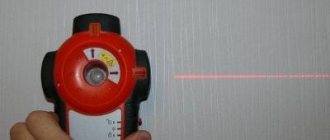
These are optical sensors that have the ability to measure the distance to an object.
Laser optical sensor
Laser optical sensor with distance display
Laser optical sensor with distance measurement
The principle of operation is to measure the transit time of the beam. Like in radar.
Slot sensors
A separate type of sensors with a receiver and transmitter are slot sensors (fork-shaped). They are convenient because although the transmitter and receiver are separated, they are actually located in the same housing, the design of which has a slot.
Slit optical sensors. Two sensors, one ring with slots.
When an activator (object) gets into the gap between the emitter and the receiver, the sensor is triggered. Slot sensors are useful where the object whose movement is detected has a small, fixed thickness. This design is very similar to the operating principle of an incremental encoder.
Fiber optic, or fiber optic
I have come across such sensors in a diffuse design, and with a receiver + transmitter.
The idea is that the optical elements and electronic circuit are separated in space, and the light is transmitted through optical fiber (plastic fiber).
Fiber Optic Sensor Element
Do you see the red dot? This is the output of the fiber optic sensor.
At a distance of 4 meters there are the following blocks of fiber optic amplifiers (for three sensors):
Fiber Optic Amplifiers for Sensors
Such a system is installed where there is very cramped space (how to set it up?) and where electronics do not like to work - vibration, humidity, and a high risk of damage.
A few more photos of sensors with fiber optic cable:
Two transceivers with fiber optic wires to the electronic unit. Do you see any abrasions? These are traces from inductive sensors that constantly broke due to imperfect mechanics...
Electronic unit (fiber optic amplifier)
Optical part of the fiber optic sensor. Even taking a photo is problematic, let alone setting it up!
Electronic units – fiber optic amplifiers for fiber optic sensors in the photo above.
Expert of the LAN-ART company on optical transmitters - Berezkin E.N.
A specialist, an expert at the LAN-ART company on optical transmitters, Evgeniy Nikolaevich Berezkin, comments: “Today in every modern home there are optical receivers and transmitters operating via fiber optics. The optical transmitter of cable television networks (CTV) is used to generate an optical signal modulated by an electrical television signal with a group TV signal frequency range of 47 ... 862 MHz. Such transmitters use lasers, and photodiodes are used in receivers. The system uses optical radiation with a wavelength of 1100-1600 nm. “
Analog
These sensors are analog based on the type of output signal. The principle of operation can be similar to that of a laser, or the intensity of the reflected signal is simply measured.
Analog sensor
In this case, an analog signal corresponding to the distance to the surface of the unwinding coil is fed to the analog input of the controller (ADC). And the controller calculates the diameter of the coil.
An optical sensor that measures the distance to an object. The red dot on the right shows the measurement location. The sensor housing is protected from impacts by a fastening element
The same sensor is shown at the very beginning of the article. It also has a discrete output that can be programmed to trigger at a certain distance.
Optical flame sensor
This sensor stands apart - it perceives light from the flame of burning gas or other fuel. Used in industrial boiler rooms where increased safety is needed.
I remembered. My article is about modernizing a boiler room, where I installed soft starters instead of contactors.
Here is the model:
Flame sensor for boiler room with discrete output
Or this:
Flame sensor from gas combustion
The principle of operation is similar to that of a radio tube.
Hey, does anyone else remember that there were analog TVs with radio tubes?! An article about how I turned on an old tube TV.
Areas of rational application of photo relays
Typical situations in which the presence of this device is required:
- When turning a circuit on and off is done using a low power signal;
- When several circuits must be controlled by a single signal.
The effectiveness of using photo relays is also determined by their versatility (in addition to standard control equipment, you can use computers or laptops). This also makes it possible to implement logical control commands such as “if...then...”.
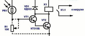
Consider the use of photo relays for street lighting. The technology of their application is based on the use of trigger FET switches.
Block diagram of photo relay with FET switch
The block diagram below uses the K series of MOS transistors. Unlike solid state relays, the circuit drives photodiodes directly. This allows for much faster switching speeds since the power-off time when the LED is turned on is not critical. Due to the lack of mechanical components, the device is highly compact, but there is no physical isolation barrier, and therefore only a low-voltage control signal must be used.
Since the photo relay is an alternative to an existing remote lighting control panel, the first thing to think about is whether such a replacement is really necessary. If the existing system is fully compliant with electrical codes, simply adding a relay panel before the load will provide full control of the lighting circuit. Up to 64 photo relays can be placed in a small housing along with a low voltage source, and a breaker panel can be placed nearby. The fewer the number of circuits, the more economical the use of a relay panel becomes.
The photo relay can be used to control single-pole 127/220 VAC circuits and two-pole (208...240 V) AC circuits. Relay panels are most economical when controlling smaller loads, but have one drawback - they are designed for a limited number of on/off cycles: from 20,000 to 50,000 (under normal circumstances, this will last about 5 years).
A general view of the block layout of a photo relay for street lighting and a wiring diagram are shown in the following figures.
There are some nuances in using photo relays in conjunction with motion sensors. As a rule, street lights are turned on all night. But at night, street lights are not needed if there is no traffic. Therefore, they are increasingly using schemes that turn on street lights only when the vehicle is moving and for some time after it. An AVR 8051 microcontroller and several pairs (the more the better) of infrared (IR) sensors are used.
Connecting a relay lighting control panel
The proposed system consists of Atmega8 microcontroller, LDR, PIR sensor and RTC. This system controls street lighting using a light dependent resistor and an IR sensor.
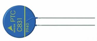
Street lights turn on depending on the intensity of the luminous flux that is perceived by the LDR. If such intensity on photoresistors is low, their resistance value is high. As the overall illumination decreases, this value increases, and thus determines when the street lights should turn on.
At night there is minimal traffic. This circumstance can be used to configure the controller. When peak time arrives, when there is no traffic, the photo relay will turn off the outdoor lighting. When a single vehicle appears, the IR sensor will send a control signal to the microcontroller. He will turn on the lighting for 2...3 minutes, after which he will automatically turn it off.
Block layout of photo relay
Scheme for switching on a photo relay for controlling outdoor lighting
Installation of motion sensors
Wiring diagram for motion control based on photo relay
Malfunctions and care of optical sensors
Just like the optics of SLR cameras, they need to be cleaned, carefully wiped and checked for mechanical integrity.
To clean optics, I use wipes soaked in water with the addition of a small amount of neutral detergent. For example, for dishes. Then I wipe it with a dry cloth. The main thing is that no abrasive gets in.
Another feature. In optical sensors, the emitting element is usually an LED. It has its own service life, and over time the intensity of its radiation decreases. Therefore, it is not surprising that once every few years it is necessary to adjust the sensitivity of the sensors, such is the problem...
Download the book about sensors
• Aleinikov A.F. Gridchin V.A. Tsapenko M.P. Sensors / Aleinikov A.F. Gridchin V.A. Tsapenko M.P. Sensors All types of sensors are considered - theory and practice, pdf, 13.21 MB, downloaded: 2741 times. / • Encoder: a must-have for a production line / Article in the magazine “Electrical Technical Market” from SamElectric.ru.
Varieties and examples of real-life applications of encoders. Descriptions of real equipment components in which encoders are used are given, pdf, 1.15 MB, downloaded: 917 times. / Everything did not fit into the article, there are many more photos and interesting stories about optical sensors, but the article is not rubber)))
Therefore, ask questions and share your experience and photos in the comments, I will be glad!
I will also be glad to increase the number of subscribers and activity in my VK group! Come in, there is the most up-to-date information, which sometimes does not even appear on the blog.
I’m also waiting for new readers and subscribers on my Yandex.Zen . By the way, here is an interesting article on the topic on Zen - varieties and examples of real-life use of encoders. Descriptions of real equipment components in which encoders are used are given.