The concept of relay protection and automation (RPiA)
Rules for technical operation and installation of electrical installations (PUE, PTE) regulate the use of relay types of protection. These devices, or rather complexes of special elements, are often combined with automation, therefore they are abbreviated as RZiA (and this is also an abbreviation without “and” or RZ).
According to PTE standards, power units and lines of electrical installations - power plants, substations, electrical networks - are protected from short circuits (short circuits), abnormal conditions, overloads by relay protection and automation units. Such devices are integrated into structures, are part of them (installed at the design stage), and less often - they are mounted separately. According to the rules, they must be in a constant state of readiness (waiting), with the exception of those withdrawn from operation according to the characteristics of their tasks, design principles, modes of power facilities, and selectivity requirements. Alarm units (warning and reporting the development of breakdowns) must also always be ready for activation.
Relay protection and automation are installed at power plants, generators, at any electrical installations, on similar large-sized powerful devices, that is, the scope of use is not limited if relay protection is required by the project. The scope of application is specified by the PUE:
Contents of Chapter 3.2 PUE:
We will explain what relay protection is more specifically, describing its purpose. When using electrical equipment and networks, there are always risks of their damage, incorrect modes, often they cannot be avoided, or such conditions are characteristic of the operation of the power plant. The most critical are overloads and short circuits. Reasons: breakdowns, damage to insulating parts, ruptures, worker errors, for example, disconnection of components under load, incorrect supply of voltage to grounded structures.
A short circuit in the area where it occurred provokes the appearance of an electric arc, the thermal effect of which leads, as a rule, to the irreversible destruction of current-carrying elements, insulating parts, and electrical devices in general (less often, but such cases are very common). In this case, high short circuit currents of thousands of amperes are supplied to the damaged segment. Almost instantaneous heating occurs; in seconds the elements heat up. Thermal processes also damage serviceable areas, causing a problem to develop and a fire to occur. On connected highways and objects, the parameters of electricity are deeply reduced, which causes electric motors to stop, and the functioning of parallel structures and generating devices is critically disrupted.
In the situations described, it is important to immediately stop the development of consequences; usually this is enough to completely prevent accidents. This is achieved by promptly disconnecting the dangerous section of the power plant, network - with automatic devices that function to disconnect contacts and de-energize. This is relay type protection, also known as relay protection or relay protection.
The relay deactivates the switches of the structure with the malfunction, while the electric arc goes out or does not even have time to arise. The flow of short-circuit amperes instantly stops, and at the same time, normal electricity levels are restored on the working part of the power plant or in the network. Damage to short-circuit equipment is minimized and eliminated, and the operating equipment mode is normalized.
Tasks:
- identifies the short circuit point, the location of the breakdown;
- quickly provides automatic shutdown, separates equipment with an unsafe factor, a dangerous segment from working structures and networks;
- detects a problem and reports it, warns about the possibility of an accident;
- creates a delay before deactivation if necessary.
Other disturbances in the power plant are also possible: overload, short circuits of various kinds, the formation of gas masses in transformers, a decrease in oil volume there, etc. If such problems are not dangerous, they correct themselves, and immediate de-energization may not be required. Usually, if the installation has constant maintenance by specialists, issuing a notification to them is sufficient. In other cases, switching off is enough, but with a pause.
Relays RZ are devices, units with an automatic principle that carry out a change in a characteristic periodic type (“relay action”, intermittently) with an established transformation (modification) of the observed characteristics.
Simply put, when detecting violations of the parameters of the power plant, the relay de-energizes and separates the contacts. Example: when the ampere on the controlled circuit critically increases (its current winding is wound there) the relay disconnects the connections to the prescribed mark.
A relay protection device is an interacting system of relays and auxiliary, automatic, device units that turn off equipment when it is damaged or under abnormal conditions.
Requirements for relay protection and automation
The requirements for relay protection are comprehensively specified in the PUE (R. 3 Ch. 3.2), as well as in numerous manuals - there is no point in duplicating them in the article. Let us summarize them so that the reader can navigate what to pay attention to, quickly find and clarify them in the indicated sources.
What principles ensure performance?
Violations in the operation of relay protection and automation equipment due to incorrect selection, installation, or non-compliance with standards:
- false alarms when the control unit and network are working properly;
- unnecessary activations, for example, when the activation of executive nodes is unnecessary;
- damage to the protection structure.
The PUE and related regulations impose requirements that exclude the above (concerning design, installation, setup and start-up, maintenance):
- compliance with classes, reliability levels;
- sensitivity;
- speed of operation;
- selectivity - ensuring protection activation levels are in the correct order. This parameter is closely related to the previous two.
Reliability
Defined by the following characteristics:
- reliability;
- compliance with the number of operation cycles specified during the creation of the relay protection;
- maintainability;
- service life, shelf life. It must be guaranteed by the manufacturer, designer in accordance with the specifications (which must be consistent with GOSTs, PUE) of the product. The product must have a passport and certificate.
Each position has its own assessment, indicated in the technical documentation, in the project approved in accordance with regulatory documents.
There are 3 positions on reliability during maintenance and operation of relay protection by activation: during internal short circuits at work locations, outside their boundaries, when functioning without faults. There are two types of reliability: operational and hardware.
Sensitivity
The requirements for relay protection and relay protection primarily relate to functional settings, since the fixation of threshold values and violation of settings imply that the relay has a certain sensitivity.
It is necessary to correctly determine what the expected degree of violation of the regime, overload is dangerous, and select a correspondingly configured version of the relay protection for it.
There is an equation for sensitivity (its numerical value) when a short circuit occurs. A special characteristic is used - Kch, coefficient.
Kch = Iкз min/Iсз
Calculation: the ratio of the smallest short-circuit current of the working area to the activation current value. The relay functions normally when Iсз < Iкз min. The most optimal sensitivity (coefficient) is 1.5–2.
Performance
The speed of de-energization has 2 components:
- triggering of protective algorithms with a command to the node below;
- activation of the switch drive.
Time response adjustable in the range min.-max. values depending on the capabilities of the relay protection device and the elements used. The response delay is created by the introduction of special relays with the ability to configure; this option is used for the most distant protections. Relay protection placed closer to the location of the problem, to the protected area, is configured for a shorter activation time interval or is used without it.
Selectivity
The second name for this characteristic is selectivity. This option allows you to determine the location of the fault in circuits of any complexity.
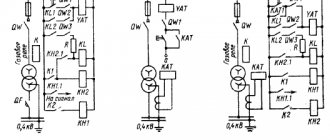
The generator generates and supplies electricity to consumers in segments 1–3 (each with its own protection). When there is a short circuit on the consumer's device at the 3rd interval, the current flows through all nodes of the relay protection, starting from the energy source. In such conditions, it is advisable to turn off the circuit of the segment with a malfunction, for example, an electric motor, leaving the remaining serviceable consumers involved. For this purpose, it is possible to make RP settings for each circuit. Typically, such features are laid down at the design stage.
Protection 5 of the 3rd segment should detect fault currents earlier and activate more quickly, disconnecting damaged segments from the circuits. Therefore, the values of the current-time settings at each interval are reduced from the generator to the consumer. Principle: the further away from the breakdown location, the less sensitivity. In this way, redundancy is simultaneously implemented, taking into account the possibility of effective protection in the event of malfunctions of any devices, including lower-level protection systems. The described scheme means that if protection 5 of segment 3 breaks down in an accident, protection devices 3 or 4 of gap 2 should be activated. And these sections, in turn, are protected by the protective units of segment 1.
What is it for?
Very often during operation of electrical systems a short circuit occurs. However, along with this, various voltage surges, current leaks, etc. can occur.
And even if such situations do not cause instant destruction of devices/objects/premises, that is, they do not pose a safety threat, then the protective devices do not act to turn them off, but to warn the personnel on duty about damage.
This is the purpose of relay protection and electrical automation.
Design features of relay protection
The relay protection device is continuously improved thanks to the introduction of innovative technologies. But the basic principles and design elements remain unchanged.
The structure of relay protection can be represented as a diagram:
Electrical signal – Process monitoring module – Logic and analysis unit – Execution unit – Signal unit
The monitoring unit monitors all electrical processes using current and voltage transformers that carry out measurements. In the logic and analysis unit, incoming signals are compared with the maximum settings. The protection will work even if there is a slight overlap between these values. The execution unit is always in a ready state, waiting for a signal from the logical unit. The signal unit operates using light or sound.
When the full protection activation cycle has passed, the specialist manually returns the device to its original state.
Relay protection: sensitivity and its coefficient
In domestic practice, the term “sensitivity” is usually used to denote a property of relay protection that makes it possible to identify calculated types of damage and abnormal modes of the power system in the coverage area of the relay protection.
In the PUE [1], the concept denoted by the term “sensitivity” [2] is used to characterize any protection, regardless of the voltage of the electrical installation, but there is no definition of the concept denoted by this term in this document.
If the sensitivity of some products can be determined directly [1], then in relay protection this characteristic is assessed indirectly, and the assessment method depends on the voltage of the electrical installation [1].
It should be noted here that in many other countries sensitivity assessment is not carried out [3].
According to the PUE, to assess the sensitivity of protection in electrical installations with voltages over 1000 V, a sensitivity coefficient is used [4, 5, 6].
The value of the sensitivity coefficient for protections that respond to an increase in the controlled value is found as the ratio of their calculated values within the protected zone to the response setting.
For line current protection, the sensitivity coefficient is generally found using the formula:
(1)
where is the minimum short circuit current for the protected line (usually at the end of the protected section); — protection operation current.
It is generally accepted that in the general case such protection will work correctly if the following relation is satisfied:
The value of the sensitivity coefficient found using this formula (1) must be no less than the normalized value established in [1], and which, depending on the type of protection, can vary from 1.5 to 2.0.
In [3] it is shown that when the value of the sensitivity coefficient changes from 1.2 to 1.4, the probability of protection operation changes slightly, from 0.998 to 1.000.
Let us now consider how it is recommended to determine the sensitivity coefficient of the current cutoff in one of the methods for calculating settings (see [4], example 2.1).
To save space, the initial data for the calculation are given in the explanations to the formulas.
The calculation begins with determining the starting current of the electric motor I start ed according to the formula:
I start ed = k start I nom = 5.7 113.2 = 645 A (2)
where k start is the catalog value of the starting current equal to 5.7 for an asynchronous electric motor of the A4 series;
I nom – rated current of the electric motor, determined from known values of rated power, rated voltage, efficiency and power, or taken from catalog data.
The starting current can also be determined from the rated current of the electric motor given in the catalog data.
The smallest value of the two-phase short circuit current at the motor terminals is found using the formula:
(3)
where – = 3500 is the value of the three-phase short circuit current at the power inputs of the asynchronous electric motor in the minimum operating mode of the system (given in the initial data for calculation).
The current cut-off current is calculated using the formula:
(4)
We find the protection sensitivity coefficient for a two-phase short circuit using formula (1), substituting the found values into it:
(5)
Based on the calculations carried out in the method [4], the conclusion was made: “the sensitivity coefficient of the TO turned out to be less than two.”
Can we say that a decrease in the sensitivity coefficient by only 7% (2.00-1.86=0.14; 0.14/2.00=0.07) compared to the value specified in the PUE makes this protection unsuitable? ?
Note that if in formula (5) the calculated value = 3031 A is used, instead of the rounded value (3000), the calculated value of the sensitivity coefficient will be only 6% (3031/1612 = 1.88) less than the value recommended by the PUE.
The approximate nature of this approach is also visible in the fact that in formula (4) the condition for the failure of the maintenance device when starting the electric motor is the choice of a multiplier equal to 2.5, which leads to an increase in the calculated current and, ultimately, a decrease in the sensitivity coefficient.
If we assume and then experimentally prove that the current cut-off will not operate when choosing a setting equal to 2.35 of the starting current of the electric motor, then the value of the sensitivity coefficient even at a starting current of 645 A will satisfy the requirements of the PUE.
In the method under consideration, instead of reducing the factor in formula (4), an action that is similar in essence is proposed - reducing the second factor by “refining” the starting current of the electric motor [2].
Note that in any case, the real starting current of the electric motor will remain unknown, and all conclusions will be based on calculations made using the catalog data of the electric motor.
The method proposes to use the well-known formula (6) to find the starting current of the electric motor using the resistance of the supply system found by calculation = 0.92 Ohm and the starting resistance of the electric motor = 5.37 Ohm:
(6)
The operating current of the current cut-off at this value of the starting current will be:
(7)
In this case, the value of the sensitivity coefficient increases to:
(8)
If we put the calculated value of current A into the original formula (5), then the value of the sensitivity coefficient will increase even more and become equal to 2.18.
After obtaining the desired result, the method [4] concluded: “The sensitivity coefficient of the TO turned out to be more than two, so there is no need to use differential protection.”
The reader can draw his own conclusion about this conclusion.
In electrical installations with voltages up to 1000 V, to assess the sensitivity of current protections, instead of the “sensitivity coefficient”, the PUE provides another characteristic - the short circuit current multiplicity, specified as a percentage in relation to:
— rated current of the fuse link;
— current setting of the circuit breaker with the maximum instantaneous release;
— rated current of the release with an unregulated inverse current characteristic;
— tripping current of the release with an adjustable characteristic inversely dependent on the current.
The current multiplicity values according to [1], depending on the type of protection device, can be in the range:
By dividing the right and left sides of the inequality by 100%, you can see that, in essence, this is a slightly modified way of specifying the sensitivity coefficient.
The above allows us to draw the following conclusions:
1.
The use of the term “relay protection sensitivity” is primarily a tribute to tradition, and the concept denoted by this term does not have a standardized definition.
2.
Assessing the sensitivity of relay protection differently, depending on the voltage of the electrical installation, creates a false impression of the difference in concepts denoted by different terms:
— “short circuit current ratio” (used in electrical installations with voltages up to 1000 V);
— “sensitivity coefficient” (used in electrical installations with voltages over 1000 V).
The standardization of the “sensitivity coefficient,” and even more so the verification of this coefficient when calculating protection settings, is largely due to the properties of previously used protection relays and was transferred to digital devices without sufficient technical justification.
Literature:
1.
Rules for electrical installations. M.: Glavgosenergonadzor of Russia, 1998, 608 p.
2.
Sensitivity // [Electronic resource “All about relay protection”], Access mode (The material was originally posted here).
3.
Shalin A.I. Reliability and diagnostics of relay protection of power systems. Novosibirsk, NSTU publishing house, 2002, 384 p.
4.
Gondurov S. A., S. V. Mikhalev, M. G. Pirogov, A. L. Solovyov. Relay protection of electric motors with voltage of 6-10 kV using BMRZ terminals. Calculation method. St. Petersburg, PEIPK, 2013, 60 p.
5.
Chernobrovov N.V., Semenov V.A. Relay protection of energy systems. M.: Energoatomizdat, 1998, 800 m.
6.
Sensitivity coefficient // [Electronic resource “All about relay protection”], Access mode.
7.
What is the protection sensitivity coefficient?//[Electronic resource], Access mode.
[1]
For example, in sensitivity metrology, measuring instruments are found as the ratio of the change in the output signal to the change in the measured quantity.
[2]
To obtain the required sensitivity coefficient, the starting current should not exceed 600 A
.
Kinds
First, we will separately describe the logical protection for buses, abbreviated as LPS. Principle: compares the state of protection of supply parts and outgoing feeders (cable outlets). Sample algorithm: the protection on one of the last ones was turned off, which means there is a short circuit on it; did not start on them at all - short circuit on bus elements. In the event of a short circuit on the tap, protections (current releases) are activated on it and on the power nodes of the section (CT inputs, segment switches).
It will be interesting➡ Potential difference
Further, upon triggering, the power parts are switched off without a pause. In the event of a short circuit on the bus parts of the distribution circuit, the relay protection on the taps does not start, and when activated on the supply nodes, it is allowed without delay.
Other types of relay protection:
| View | Description |
| Max. current (MT) | Trip factor - determination of the number of Amperes (set). |
| Directional max. (MTZ) | Additionally controls the direction of power. |
| Gas (GZ) | To deactivate CTs and VTs in the event of internal breakdowns accompanied by the formation of gases. |
| Differential | On generating units, VT, CT, buses. The currents are compared at the input. into the protected structure and at the exit, the system registers the difference and if the limit limits of the setting are violated, it is triggered. |
| Remote (DZ) | It is activated when the resistance decreases, which is typical during a short circuit. |
| Remote sensing with RF blocking | Together with earth fault protection (GF). For faster de-energization during short circuit. If there is a serviced overhead line with input. and out. DZ and ZZ, then the short circuit on such a line is usually deactivated by levels 1–3 of this system with a pause from 0 to several seconds. And HF blocking of remote protection and external protection creates a 2-way shutdown of the section without a pause for all possible short circuits in any locations. |
| Remote sensing with optical cable blocking | A high-quality replacement for the previous version. The need to maintain HF equipment is eliminated, reliability increases, since optical instruments are more stable and less susceptible to interference. |
| Dugovaya | To prevent ignition of switchgear, KTP 6.3 and 10.5. Mounted at the connection points, it is triggered by increased illumination through optical detectors, as well as by excessive pressure through sensors (valves) for this parameter. It is possible to respond to current protection (its control), used to exclude false activations. |
| Differential-phase (DPZ) | It's high frequency. The principle is to control the phases and operate when the number of Amperes on them violates the setting. |
Basic requirements for relay devices
The main properties of the relay are as follows:
- Selectivity. This parameter is characterized by the system’s ability to turn off damaged areas, while undamaged elements remain on. There are two types of relay: the first is relay with medium selectivity (overcurrent and distance protection); the second is protection with complete selectivity (differential protection).
- Relay response speed (response speed). If the response speed of the system is high, then the likelihood of any damage or accidents will be lower. The period of time after the occurrence of an accident and before the damaged device is switched off from the network is called the relay protection response time. This is the main indicator of this parameter.
- The ability of the relay to respond even to minor emergency parameters is called the sensitivity of the relay. This parameter can be assessed using the sensitivity coefficient.
- The property in which a relay protection device operates for a certain time with the specified functions is called reliability. There are two main indicators of this parameter: the number of deviations per unit of time and the period of time of correct operation.
That is, the purpose of a relay protection and automation system with the above properties is that the device should signal an operating signal about damage, instantly disconnect a broken element from the power supply, quickly respond to any changes during operation, and generally provide control over the operation of electrical appliances.
Principles for constructing a circuit of protective devices
Despite the fact that the market currently offers a large number of different relay protection devices, the basic algorithm of the processes remains the same, only being modernized for each specific case. The main protection functions are demonstrated by the block diagram.
You can learn more about the structural diagram of protection and other relay protection organs in our article Basic relay protection organs.
Relay protection classification
The relay classification system is quite diverse. Next, we will look at the main characteristics by which relays (electrical switches) are divided:
- By type of connection: electrical switches connected to the network without any auxiliary devices are called primary; relays connected using auxiliary devices (for example, a voltage transformer) are called secondary.
- By type of operation: relays that have moving components are classified as electromechanical/induction relays; electrical switches without moving components are called static (for example, electronic, microprocessor, etc.).
- By type of purpose: electrical switches that carry out measurements of various physical quantities - this is a measuring relay (for example, current, temperature, power, etc.); mechanisms that transmit action to other devices are called logic/auxiliary relays. The last group of relays is also capable of withstanding time, etc.
- According to the type of action on the controlled component: an electrical switch connected automatically to the device being switched off is classified as a direct-acting electrical switch; relays that regulate the electrical circuit of electromagnets, turning off the switching device.
If we talk about relay protection, then there are a large number of types of relay protection, for example:
- Protection of electrical appliances and electrical circuits, which is triggered when a predetermined value of electric current is exceeded, is called relay current protection. This includes: maximum relay current protection (MCP) - provides protection of devices from current that exceeds the rated value. Current cut-off (TO) - quick elimination of short circuits that appear in front of the work area. Directional maximum current protection (NMCP) - in this case, power direction control is added to the protection of relay devices from currents.
- If the temperature in the transformers rises, which is accompanied by the formation of gases and as a result, the power supply to the devices from the network is cut off. This type of protection is called gas protection.
- A protection based on a comparison of the current in front of the protected section and the current at the end of this section is called differential protection.
- Determining the distance to the point of occurrence of a short circuit using resistance, such relay protection is called distance protection. There are two subtypes of distance relay protection: 1) using blocking and high frequency; 2) using blocking through the optical channel.
- Relay protection based on the response of an optical sensor due to strong lighting and a sensor due to high pressure, such protection is called arc protection.
- The protection used when determining a short circuit in buses is called logical bus protection (LBP). It is necessary to reduce the time when disconnecting a short circuit.
- The protection based on the comparison of current phases at the ends of the power line is called differential-phase protection (PDP). When the set value is exceeded, the relay is activated.
In addition to the main types of relay protection, below we will talk about the types of automation in relay protection, which, in comparison with relay protection, do not turn off, but turn on the power supply after an accident.
- Automation, which is used to turn on an entire line or a separate phase of the line after it has been disconnected due to the applied protection, is called automatic reclosure (AR). There are two subtypes of automatic reclosure: mechanical and electrical. They are used in power lines with voltages over 1 kV, as well as in the assembly of substation busbars, electric motors and transformers.
- Automatic switching on of a reserve (ATS), the purpose of which is an uninterrupted supply of electricity to devices and allows you to instantly switch on backup equipment.
- If the frequency in the power supply network decreases and at the same time third-party electrical appliances are switched off, then this type of automation is called automatic frequency unloading.
It will be interesting➡ Reversing magnetic starters
We have told you a small part of what purposes and in what areas RP is used. Now it remains to consider the design of the relay protection.
The main tasks and functions of relay protection and automation services and electrical laboratories of power systems
In addition to the devices and relay protection systems listed above (clause 1.1), the installation, commissioning and operation (maintenance) of which is usually carried out by the relevant personnel of the relay protection services (especially at the level of non-centralized management), the following devices are included in their scope of activity:
a) automatic oscilloscopes, emergency event recorders (RAS);
b) transmission of alarm signals and commands (PASK), i.e. telecasts of disabling, enabling or blocking commands via high-frequency (HF) channels, cable communication lines and fiber-optic communication lines (FOCL), including HF line protection transceivers, high-frequency tele-shutdown devices (HFTO), ANKA-AVPA equipment, AKAP, filters connections, RF cables, adjustment elements, etc.;
c) secondary circuits of the devices listed above, circuits and control equipment of switches, disconnectors, short-circuiters, separators and circuit breakers for voltages above 1000 V, internal emergency and warning alarms and other secondary circuits of generators, synchronous compensators, autotransformers, transformers, reactors, buses and connections for voltages above 1000 V (including connections for own needs), power lines and large electric motors, including busbars, rows of clamps, control cables, relay equipment;
d) the electrical part of the electromagnetic interlocking of switches and disconnectors, including the rectified voltage supply device for the circuits of this interlocking (in terms of operation);
e) automation of cooling systems for autotransformers, transformers and reactors; automatic and remote voltage regulation of transformers and autotransformers under load (ARPN); electrical automation of compressor units of air circuit breakers;
f) URZA power supply systems (converter units and power cabinets), DC system insulation monitoring devices.
A significant part of the work on the operation of relay protection and automation devices and systems of network enterprises is carried out by the relay protection and automation services of production departments ( SRZA PO )
, and at power plants and cascades of hydroelectric power stations of generating companies (OGK, TGC, RSK) - by relay protection services or
electrical laboratories (
ETL ) [7].
These services are structural divisions of the corresponding PMES, RSK or ES. They carry out the necessary set of organizational and technical measures to implement, improve and maintain a high level of operation of automatic protection devices, electrical measuring instruments, as well as their secondary circuits in order to ensure reliable and economical operation of network enterprises or power systems.
The relay protection and automation service of the software department is directly subordinate to the chief engineer of the corresponding production department of the electrical network enterprise (EPS), ETL – to the head of the electrical department of the power plant (hydroelectric power plant cascade); the head of the ETL can simultaneously perform the functions of the deputy head of the electrical shop for relay protection and automation. In operational and technical terms, SRZA PO is subordinated to higher-level relay protection and automation services (MES, RDU), and ETL is subordinated to the relay protection and automation services of OGK, ODU, RDU.
SRZA PO and ETL perform the tasks of equipping power lines, buses, transformers, autotransformers, generators, synchronous compensators and other equipment located or transferred to the operational control or operational supervision of the PES dispatcher (ES shift manager), as well as providing operation of all URZA.
Based on the specified tasks, SRZA software (ETL) performs the following main functions :
1. For URZA power transmission lines and electrical equipment located or transferred to the operational management of enterprises:
a) develops measures for emergency protection systems that increase the reliability of the enterprise, and ensures the implementation of these measures;
b) selects the principles of implementation of URZA, their types, operating algorithms, placement; calculates and selects settings and characteristics, and also systematically analyzes their compliance with the actual operating modes of power lines and electrical equipment and makes the necessary adjustments to settings and characteristics;
c) ensures the serviceable condition and maintains the URZA, PA and ARFM systems; ensures compliance with the settings and characteristics specified by higher-level relay protection and automation services, as well as those selected by relay protection and automation software (ETL);
d) ensures good condition and maintains electrical measuring instruments and their secondary circuits;
e) draws up instructions and operational instructions for maintenance of emergency protection equipment, emergency control equipment, and weapons of mass destruction on power lines for PMES dispatchers and operating personnel of power plants, indicating the accepted methods for determining short-circuit locations.
2. Participates in the preparation of technical specifications for the design of new facilities in terms of relay protection systems (principles of implementation, types, structural or circuit diagrams), submits for approval by the Relay Protection and Automation Center projects of relay protection and automation systems for intra-system power lines and electrical equipment of 110 kV and above.
3. Prepares operational requests and programs for work with emergency protection equipment and for work on power lines and electrical equipment, requiring an analysis of the need for operations with emergency protection equipment.
4. Draws up a schedule for URZA maintenance.
5. Performs restoration work, reconstruction and modernization
equipment and circuits of emergency protection systems required during the maintenance process, as well as replacement of worn-out and obsolete emergency protection systems.
6. Coordinates the launch schemes the volumes of emergency protection devices provided for in them . Draws up work programs for testing URZA when commissioning new power lines and electrical equipment, after their major repairs and during special tests, takes direct part or provides technical supervision during these tests.
7. Receives newly switched on automatic protection devices from installation and commissioning organizations and participates in commissioning work before switching on the automatic protection devices introduced at this facility for the first time.
8. Participates in commissions to investigate technological violations in the electrical part of the enterprise; Conducts extraordinary inspections of URZA after incorrect and unclear actions; promptly takes measures to eliminate the causes of incorrect actions of URZA.
9. Keeps a log of relay protection and automation at the control center of the power plant and control panels of power plants, cascades of hydroelectric power stations, and substations.
10. Prepares and maintains established technical documentation for relay protection and automation ; maintains systematic records of the work of URZA, analysis of their work in case of technological violations of the normal operating mode of the enterprise, and established reporting. Monitors the operation of the automatic relay protection devices on a daily basis, summarizes the experience of their operation, promptly informs higher-level relay protection and automation services about identified defects in these devices and, if necessary, draws up complaint reports or claims reports to the manufacturing plants.
11. Organizes technical training for SRZA
Software (ETL) and exams to test their knowledge of PTE, PTB, PPB and the rules of technical maintenance of URZA. Conducts examinations for the admission of personnel to independent inspections of URZA.
12. Places automatic oscilloscopes and emergency event recorders (ER) on power lines and electrical equipment.
13. Participates in organizing the operation of fixing devices
and other stationary and portable devices for weapons of mass destruction on power lines.
14. Performs examination of projects for URZA ; coordinates the placement of arc suppression reactors in networks with an isolated neutral.
15. Prepares annual requests for relay equipment, spare parts for it, control cable, test devices, etc.
16. Can perform the functions of the metrological service of the enterprise and ensure the reliability of primary information about electricity in the AMR system.
Organization of management . The staff of the SRZA PO (ETL) may include: chief, deputy chief, laboratory chief, heads of sectors (groups), leading engineers, engineers of all categories, senior foremen, foremen, technicians, electricians.
functional sectors (groups, teams) may be included in the structure of the relay Relay protection and automation of electrical networks with voltage 6-10 kV; emergency automation; operational and settlement; relay automation laboratory, workshop, etc. Sectors (groups, brigades) can also be organized on a territorial basis.
The ETL may include the following functional groups (teams) for maintenance:
- Relay protection and automation devices and secondary circuits of switchgear connections 35 kV and higher ( open switchgear group );
- relay protection and automation devices and secondary circuits of generators, transformers, generator-transformer units, auxiliary transformers ( main circuit group );
- PA devices and ARFM systems ( automation group );
- generator excitation systems ( excitation group );
- relay protection and automation devices and secondary circuits of connections for own needs (MV) 6-10 kV ( MV group 6-10 kV );
- the same 0.4 kV ( MV group 0.4 kV );
- measurement group , as well as other groups.
The functions of individual sectors (groups) can be combined. Regardless of the structure of the SRZA software (ETL), each RPZA must be assigned to a specific employee .
Main tasks of selective protection
Selectivity is a process that means selection (selection). This term is applicable to different industries and areas of human activity. For example, in chemistry, when chemical reactions occur, they talk about the selectivity index. In this case, the selectivity of chemical transformations is considered.
As for a person, his perception of the world around him, the choice of information, as well as its memorization are selective.
What is selectivity in electrical engineering, and why is it needed?
The tasks of electrical selective protection include:
- guaranteeing the safety of equipment and operating personnel;
- instantly identifying the location of the fault and disconnecting only the faulty section;
- reducing the negative effects of the accident on other components and parts of electrical appliances;
- minimizing damage to the faulty area;
- guaranteeing maximum continuity of operation of the electrical system;
- achieving ease of operation of electrical equipment.
In addition, selectivity reduces the consequences of short circuits and the load on the device.
Selectivity map and rules for its creation
The diagram of the approved sample, on which all current parameters of protective devices and devices are plotted, indicating the common power source, is carried out on a scale convenient for viewing. This is a selectivity map. It ensures maximum use of the protective qualities of circuit breakers. All processes possible during operation are displayed graphically.
The following must be included on the map:
- places of important calculation points;
- protective characteristics of automatic circuit breakers and possible short circuits, while their min and max values are indicated.
This map serves as the basis for compiling a table for the selection of protective devices. In addition, the map allows you to evaluate the overall protective selectivity and provides complete information about the mutually agreed upon settings of all machines.
The map is constructed along axes. The abscissa axis represents current values, and the ordinate axis represents time values.
For your information. Other types of characteristics can be applied to the axis. Each scheme includes the parameters of two or three machines. The construction of such maps can be done using a computer program.
An example of a selectivity map made using the program
Properly executed selective protection allows you to preserve equipment. When a specific section is turned off, it allows you to turn the power back on using an automatic transfer switch (ATS) and minimize equipment downtime and interruptions in the supply of electricity to consumers.
Calculation of selectivity of machines
In most cases, protection devices are not some kind of tricky devices, but standard and well-known circuit breakers. To provide them with the correct selectivity, you just need to select the right parameter settings. The operation of such units is based on the following condition:
Is.o.last ≥ Kn.o.* I k.pred., where:
- Is.o.last - the current at which the protection begins to operate;
- I k.pred. — short circuit current at the end of the protective zone;
- Kn.o. — reliability coefficient, which depends on a number of settings.
You can calculate selectivity when controlling devices over time using the following scheme:
tс.о.last ≥ tк.prev.+ ∆t, where:
- tс.о.last and tк.prev. — time intervals through which the circuit breakers are triggered in order of proximity to the power source;
- ∆t is the time step of selectivity.
How does radio relay work?
The operating principle of radio relay communication is simple. An intermediate link is used between the receiver and transmitter - a radio relay complex. And from it it is transmitted to the receiver. Thanks to this approach, it became possible to transmit the VHF range over considerable distances. The need for radio relay communications became acute when equipment capable of transmitting the HF range ceased to satisfy the maximum volume.
Signal reception and transmission during RRL is carried out in the UHF range:
- 460 to 470 MHz;
- From 1,300 to 1,600 MHz;
- From 1,700 to 2,300 MHz.
Centimeter waves are sometimes used, but the meter range is only needed in special cases. Frequencies above 10 GHz do not make sense in radio relay communications due to their great vulnerability in precipitation conditions.
Selectivity tables
Selective protection operates mainly when the In rating of the circuit breaker is exceeded, i.e., under small overloads. With short circuits it is much more difficult to achieve. To do this, manufacturers sell products with selectivity tables, with which you can create bundles with selectivity of operation. Here you can select groups of devices from only one manufacturer. Selectivity tables are presented below; they can also be found on enterprise websites.
To check the selectivity between the upstream and downstream devices, the intersection of the row and column is found, where “T” is complete selectivity, and the number is partial (if the short-circuit current is less than the value indicated in the table).
Advantages of RRL
There are quite a lot of advantages in radio relay communication. It is precisely because of its advantages that this technology has not been completely forgotten by scientists:
- Using radio relay repeaters, a significant amount of information can be incorporated into the signal;
- Due to the linear propagation of the VHF range, good directionality of the signal is obtained. This parameter increases with increasing antenna area;
- Weather conditions and seasons have minimal impact on the quality of reception and transmission;
- With the use of radio relay communication, there is no need to lay long cables in difficult natural conditions. For example, technically laying wires in swampy or rocky areas is very difficult and expensive. This is especially true for underwater installations. Also, when transmitting data over long distances by wire, the signal power is significantly reduced, which must be replenished every 6 km.
These are just the main advantages of radio relay communication. To this list we can add savings in non-ferrous metals - copper and aluminum, which are used for wired transmission of RF signals.
Operating principle of differential protection
The basis of the operating principle of any differential protection is the control of currents at the beginning and end of the protected section of the electrical circuit. Current transformers are used for this. When located within the same switchgear, they are connected to the protection device directly using cables. If the boundaries of the protected area are located at a large distance from each other, which is typical for cable or overhead lines, two half-sets of protection are used, connected to each other by an auxiliary cable line.
If these currents at the beginning and end of the protected section are equal to each other and directed in one direction, no operation occurs. This happens when rated load currents flow or during a short circuit outside the protected area (external short circuit currents).
But if the damage occurs in an area controlled by the protection, the power of the electrical network flows to the short circuit point. With one-way power supply (for transformers or generators), more current flows from the source towards the protected electrical device than is given to the consumer. With two-way (on a cable or overhead line connecting networks with independent power sources), the currents at both ends of the line are oriented to the point of damage.
A reason is created for the protection to operate, which gives the command to turn off the object simultaneously from all sides.
Depending on the characteristics of the protected object, appropriate differential relays are selected for the implementation of devices. Let's consider their features.
It will be interesting➡ Twisted pair: categories, crimping, work tips
Details about the operating principle of the differential. protection, watch the video:
Speed principle
The essence of this principle is to de-energize the area where the problem occurred in order to avoid an emergency.
Two components are important for this:
- Protection response speed;
- Action switch.
The protection speed can be adjusted by entering a specific value, the number of which is directly related to the protection device. You can apply a parameter such as a time delay. It can be used when working with remote security systems.
Purpose of automatic reclosing
Purpose of automatic reclosing
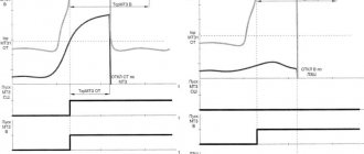
Automatic reclosing is designed to close circuit breakers after a fault has de-energized a line. At the same time, automatic reclosure makes it possible to reduce interruptions in power supply by the number of short-term accidents. Look at Figure 1, in the event of a short circuit at point K1 followed by tripping of the high-voltage switch Q1, automatic reclosure 1 is triggered. Let’s assume that the short circuit has resolved itself and the supply to the line from substation PS1 to PS2 has been restored.
At the same time, when there is a short circuit at points K2 and K3, switch Q2 cuts off the line to substation PS3. Let’s assume that these are established short circuits; when autorecloser2 is triggered, the voltage will be supplied to the network again, but since a short circuit occurs at points K2 and K3, Q2 will turn off the line again.
Therefore, all emergency situations according to their duration can be divided into:
- Short-term - those that are caused by a relatively short-term factor (movement of animals, falling branches and other elements), which created the flow of short circuit currents for a fraction or a few seconds, after which both the cause and the circuit eliminated themselves.
- Established - caused by a constant factor that cannot go away without personnel intervention (wire breakage, insulation destruction, etc.). In such situations, persistent short circuits occur, which can only be eliminated by turning off the switches and subsequent repairs.
In practice, automatic re-closing works in all situations, but successful re-closing only occurs when the cause has been eliminated, that is, in the case of short-term faults. If, after the first restart, automatic recovery does not occur, depending on the type, the following restart stages may be applied. Depending on local conditions, automatic reclosure systems may have different operating features.
Since 50% of all outages can be re-energized with a single autorecloser, the first stage is considered the most effective. The second is adjusted with a time interval of several seconds or tens of seconds, and, as statistics show, it allows the consumer to be powered in another 15% of cases.
Requirements
To ensure the declared modes and safe operating conditions of the equipment, a number of requirements are imposed on automatic restart devices:
- Performance – must ensure the transition speed determined by the type of powered devices and consumer category. But, at the same time, the speed should not restart until the electric arc has completely dissipated. Because otherwise, even with short-term damage, re-ionization of the insulating gap is possible.
- Resistance to emergency mode - TAVR and backup protection devices should not reduce the quality and speed of response due to changes in electrical quantities.
- Automatic reclosure selectivity - the system must adjust its operation in accordance with other emergency automatic devices, without interrupting the operation of the protection.
Figure 3: Coordination of automatic reclosure with other protections - In case of operational shutdowns for the purpose of carrying out scheduled work, the automatic recloser must be removed from the circuit so as not to mistakenly apply voltage to the substation busbars and not endanger personnel.
- After the reclose has been triggered, the switching device must return to the closed position. If the reclosure is unsuccessful, there should be an automatic return to the open position.
- For some types of protection (gas, differential and others that react to damage to the transformer), a ban on restarting should be established. Also, the disabled position must be maintained in the event of an emergency mode in power electrical machines.
- When restarting, uncontrolled multiple reclosures must be blocked in order to avoid the destructive effects of sustained short-circuit currents on devices.
Increase in current during short circuit
History of radio relay communications
The idea of radio relay communication was first proposed in 1898 in the journal Electronics Notes. The article was written by Johann Mattausch. Despite a lot of criticism, a year later Emil Guarini-Forestio constructed a workable copy. He patented a radio repeater on May 27, 1899 - this is the date of the birth of radio relay communications.
For many years, engineers have been trying to make the new method of data transmission possible for practical use. Massive antennas were installed, filters were added, but due to imperfections in the design, the idea had only theoretical meaning.
The real use of radio relay communication became possible only 30 years later, when high-frequency radio tubes were invented. In the 30s of the twentieth century, thanks to radio relay communications, countries began to abandon the laying of telegraph cables in difficult conditions, and began to install powerful intermediate receivers/transmitters.
Radio relay lines were used in World War II. Today, land-based mobile networks use the principles of radio relay communications. RRL is also used for military purposes to control troops. Scientists are thinking about the possibility of energy transfer. Nikola Tesla had this idea, but he was unable to implement it.