The invention of electricity brought humanity to a new frontier of development. Technological progress relied on two directions of movement using electricity. In one case, direct current was used, in the second - alternating current. The introduction of electricity sources and power consumers resulted in a hundred-year war between adherents of the two types of energy. In the end, those who promoted the idea of widespread use of its variable form won.
Sine wave of alternating electricity in the coordinate system
General concept of alternating current
Unlike electrons constantly moving in one direction, alternating current changes both direction and value several times per unit of time. Changes occur according to a harmonic law. If you observe a similar signal using an oscilloscope, you can see a picture in the form of a sine wave.
Relative to the ordinate axis OY, the current changes its direction from positive to negative and does this periodically. Therefore, its instantaneous value in the first position is considered positive, in the second - negative.
Important! Since alternating current is an algebraic quantity, we can talk about its sign of charge only for a specific instantaneous value, depending on the direction in which it flows at that moment.
Signal on the oscilloscope screen
How can you get alternating electric current at home?
Let's assume that we have some structure that is capable of conducting alternating electric current. What happens if she falls under the influence of a force field?
If you follow the formulas that we gave above, when rotating, an alternating current of a certain intensity will flow through this structure.
If the structure turns evenly, then an alternating electric current circuit is formed at its ends. It will have the shape of a sinusoid.
This whole process is explained by the fact that a large number of different power flows pass through the structure in its different positions.
If the structure rotates, then the value of the electromotive force will not be distributed evenly, but will correlate with the position of the axes of the structure.
When obtaining the turnover of a conductive structure, both the frequency of the alternating electric current and the value of the driving force at the ends of the product will depend on the number of revolutions in a certain time.
In order for the driving force to reach a certain value at a stable frequency, a number of windings are added on the conductor. Because of this, the conductive structure turns into a coil.
In industry, an alternating electric current circuit is formed according to the same principle. Nowadays you can find many power stations that use generators with this electric current.
Most often, synchronous motors are used, which are convenient to regulate the frequency and magnitude of the electromotive force of alternating current. In addition, they are resistant to outbreaks of overloads in the electrical network.
Three-phase generators have become widely popular at power plants.
This option was chosen from the point of view of economy and technical characteristics, which are necessary to obtain a moving force field.
And without it, not a single electric motor will work, which underlies the operation of any electrical production in our country.
The moving part of any engine (rotor) is driven by certain forces. The number of poles can be completely different, however.
For example, if the moving part rotates at a speed of 3000 revolutions per minute, then in order to obtain an alternating current with a frequency of about 50 Hz, a generator with double polarity is needed.
If the number of revolutions is halved, the number of poles increases with inverse proportion.
On the movable part of the engine (rotor) there is an excitation winding through which electric current is supplied from the exciter generator. The current can also come from a semiconductor stimulus using a mechanism with special brushes.
Unlike commutator motors, the brushes are on rings. This ensures that the force field of the windings changes in magnitude while regulating the exciter current. In this case, the force field of the coil remains unchanged in sign and direction.
Based on this operating principle, the preferred conditions are selected to maintain the operation of the alternating current generator.
As we see, alternating electric current for large-scale production is formed using the phenomenon of electromagnetic induction.
The example is considered on the basis of generators with three phases. At home, generators with one phase can also be used.
For repair work, three-phase mechanisms are most often used. This is explained by the fact that the main construction equipment is powered from a three-phase network. These are, for example, concrete mixers, circular saws, and some models of welding equipment.
Please note that only synchronous generators are suitable for generating electric current. Asynchronous motors cannot withstand heavy loads. They are most often purchased to provide electrical power to dachas or cottages.
Periodic alternating current
One that, while changing, manages to return to its original value at equal time intervals and at the same time goes through the entire cycle of its transformations, is called periodic. It can be traced on a sinusoid displayed on the oscilloscope screen.
Period and amplitude of sinusoidal oscillation
Resonance frequency: formula
It can be seen that at regular intervals the graph repeats without changes. These intervals are designated by the letter T and are called periods. The frequency with which a certain number of similar periods fits into a unit of time is the frequency of an alternating current.
It can be calculated using the AC frequency formula:
f = 1/T,
Where:
- f – frequency, Hz;
- T – period, s.
Frequency is equal to the number of cycles per second and has a unit of 1 hertz (Hz).
Attention! The SI unit of frequency is named after Heinrich Hertz. 1 hertz (Hz, Hz) = 1 s-1. Multiple and submultiple units, expressed by standard SI prefixes, are applicable to it.
Frequency standards
In order to ensure coordination of the operation of sources of alternating electricity, transmission systems, reception and operation of electrical consumers, frequency standards are applied. Frequency used in electrical engineering in some countries:
- 50 Hz – countries of the former USSR, the Baltic states, European countries, Australia, North Korea and others;
- 60 Hz is the standard adopted in the USA, Canada, the Dominican Republic, Taiwan, the Cayman Islands, Cuba, Costa Rica, South Korea and some other countries.
In Japan, both frequencies are used. Eastern regions (Tokyo, Sendai, Kawasaki) use 50 Hz. Western regions (Kyoto, Hiroshima, Nagoya, Okinawa) use a frequency of 60 Hz.
For your information. The railway infrastructure of Austria, Norway, Germany, Switzerland and Sweden still uses the 16.6 Hz frequency.
Electric current frequency - definition, physical meaning
Alternating current has a number of important characteristics that affect its physical properties. One of these parameters is the AC frequency. Speaking from the point of view of physics, frequency is a certain quantity that is the reciprocal of the period of current oscillation. To put it simply, this is the number of complete cycles of EMF changes that occur in one second.
It is known that alternating current causes electrons to move in a conductor, first in one direction, then in the opposite direction. They complete the full round trip in a certain period of time called the alternating current period. frequency is the number of such oscillations per second.
Vasiliev Dmitry Petrovich
Professor of Electrical Engineering, St. Petersburg State Polytechnic University
Ask a Question
The unit of frequency measurement used throughout the world is 1 Hz (in honor of the German scientist G. Hertz), which corresponds to 1 oscillation period per 1 second.
In the republics of the former USSR, the standard current frequency is 50 Hz .
This means that the current sinusoid moves within 1 second 50 times in one direction, and 50 in the opposite direction, passing through zero value 100 times. It turns out that an ordinary incandescent lamp, connected to the network with such a frequency, will fade and flash approximately 100 times per second, but we do not notice this due to the peculiarities of our vision.
To measure the frequency of alternating current, instruments called frequency meters are used. Frequency meters use several basic measurement methods, namely:
Methods for measuring the frequency of electric current
Discrete counting method;
Capacitor recharging method;
Resonance method for measuring frequencies.
Frequency comparison method; as:
The discrete counting method is based on counting pulses of the required frequency for a specific period of time. It is most commonly used by digital frequency counters, and it is through this simple method that fairly accurate data can be obtained.
You can learn more about the frequency of alternating current from the video:
The method of recharging a capacitor also does not involve complex calculations. In this case, the average value of the recharge current is proportional to the frequency, and is measured using a magnetoelectric ammeter. The instrument scale, in this case, is calibrated in Hertz.
The error of such frequency meters is within 2%, and therefore such measurements are quite suitable for domestic use.
The resonant measurement method is based on electrical resonance that occurs in a circuit with adjustable elements. The frequency that needs to be measured is determined by a special scale of the adjustment mechanism itself.
Abrahamyan Evgeniy Pavlovich
Associate Professor, Department of Electrical Engineering, St. Petersburg State Polytechnic University
Ask a Question
This method gives a very low error, but is only used for frequencies above 50 kHz.
The frequency comparison method is used in oscilloscopes and is based on mixing the reference frequency with the measured one. In this case, beats of a certain frequency occur. When the frequency of these beats reaches zero, the measured frequency becomes equal to the reference one. Next, from the figure obtained on the screen using formulas, you can calculate the desired frequency of the electric current.
Another interesting video about AC frequency:
Alternating sinusoidal current
Rotation speed: formula
This is the current that changes periodically over time, and its changes obey the sinusoid law. This is the elementary movement of electric charges, therefore it cannot be further decomposed into simple currents.
The type of formula for such an alternating current is:
i = Im*sinωt,
Where:
- Im – amplitude;
- sinωt – phase of sinusoidal current, rad.
Here ω = const is called the angular frequency of alternating electricity, and the angle ωt is in direct time dependence.
Knowing the frequency f of the original current, you can calculate its angular frequency using the expression:
ω = 2πf = 2π/T.
Here 2π is the value of the central angle of the circle expressed in radians:
- T = 2 π radians = 3600;
- T/2 = π = 1800;
- T/4 = π/2 = 900.
If we express 1 rad in degrees, it will be equal to 57°17′.
Sinusoidal alternating motion of electrons
What is AC voltage?
As you know, electric current is the ordered movement of charged particles that occurs under the influence of a potential difference or voltage. One of the main characteristics of any type of voltage is its dependence on time. Depending on this characteristic, a distinction is made between constant voltage, the value of which practically does not change over time, and alternating voltage, which changes over time .
To assemble a radio-electronic device, you can pre-make a DIY KIT kit using the link.
Alternating voltage, in turn, can be periodic or non-periodic. Periodic voltage is a voltage whose values are repeated at regular intervals. Non-periodic voltage can change its value at any time period. This article is devoted to periodic alternating voltage.
Constant (left), periodic (center) and non-periodic (right) alternating voltage.
The minimum time during which the alternating voltage value is repeated is called period . Any periodic alternating voltage can be described by some functional relationship. If time is denoted by t, then such a dependence will have the form F(t), then in any period of time the dependence will have the form
where T is the period.
The reciprocal of the period T is called the frequency f. The unit of frequency is Hertz and the unit of period is Second
The most common functional dependence of periodic alternating voltage is a sinusoidal dependence, the graph of which is presented below
Sinusoidal alternating voltage.
It is known from mathematics that a sinusoid is the simplest periodic function, and all other periodic functions can be represented as a number of such sinusoids having multiple frequencies. Therefore, it is necessary to initially consider the features of sinusoidal voltage.
Thus, the sinusoidal voltage at any time, the instantaneous voltage , is described by the following expression
where Um is the maximum voltage value or amplitude,
ω – angular frequency, rate of change of argument (angle),
φ – the initial phase, determined by the displacement of the sinusoid relative to the origin, determined by the transition point of the negative half-wave to the positive half-wave.
The quantity (ωt + φ) is called phase , characterizing the voltage value at a given time.
Thus, the amplitude Um, angular frequency ω and initial phase φ are the main parameters of the alternating voltage and determine its value at each moment of time.
Usually, when considering a sinusoidal voltage, it is considered that the initial phase is zero, then
In practice, quite often, a number of other parameters of alternating voltage are used, such as effective voltage, average voltage and shape factor, which we will consider below.
Polyphase AC
AC symbol
To start and operate many industrial devices and electrical equipment, not one phase, but several are required. In this regard, concepts such as two-phase and three-phase alternating currents are considered.
Three-phase current
This type of electricity is used in a three-phase system, which includes three single-phase circuits. The circuits have an EMF of variable nature of the same frequency. These emfs are phase shifted relative to each other by ϕ = Т/3 = 2π/3. Such a system is called three-phase current, and the circuit is called a phase.
The generation, conversion, delivery and consumption of alternating electric current mainly occurs through a three-phase power supply system.
Three-phase alternating current
Two-phase current
Back in 1888, Nikola Tesla described how a two-phase network could be used in practice, and proposed the design of a two-phase motor he developed. Such networks began to be used at the beginning of the 20th century. They consisted of two circuits.
There, the circuit voltages were shifted in phase by 900. Each phase included two wires; two-phase generators had two rotors, also structurally rotated at an angle of 900.
Important! Such networks made it possible to soft start two-phase electric motors from almost zero torque. While starting a single-phase asynchronous motor requires an additional starting winding or starting system.
Two-phase voltage graph and schematic drawing of a two-phase generator
Effective value of sinusoidal current
Effective value refers to its effectiveness. It is equal to the value of direct current that will do the same work as alternating current in one period of time. By work here we mean its thermal or electrodynamic orientation. It is most convenient to use the rms value of alternating electricity.
Then the effective value for the sinusoidal current is determined by the formula:
I = * Im ≈ 0.707 * Im,
where Im is the magnitude of the current amplitude.
RMS current value
AC generation
In addition to standard generators, inverters and phase splitters are used to produce alternating current.
Inverter
This is a device with the help of which direct current is converted into alternating current. During this process, the output voltage also changes. The device circuit is an electronic generator of a sinusoidal pulse voltage of a periodic nature. There are options for inverters that operate with a discrete signal. Inverters are used for autonomous power supply of equipment from constant voltage batteries.
Inverter 12/220 V, power 1500 W
Phase splitter
Another way to get multiple phases from a signal is to split it into several phases. This is done using a phase splitter. Forced processing of digital or analog signals is used both in radio electronics and power electrical engineering.
To supply power to three-phase asynchronous motors, a phase splitter based on them is used. To do this, the windings of a three-phase motor are connected not by a star, but in a different way. Two coils are connected to each other in series, the third is connected to the midpoint of the second winding. The motor is started as a single-phase one, after acceleration, an EMF is induced in its third winding.
Interesting. In the case of phase splitting using this method, the phase shift between windings 2 and 3 is not 1200, as it should ideally be, but 900.
Electromagnetic induction and Faraday's law
Michael Faraday in 1831 discovered a pattern that was later named after him - Faraday's law. In his experiments he used 2 settings. The first consisted of a metal core with two wound and unconnected conductors. When he connected one of them to a power source, the needle of the galvanometer connected to the second conductor twitched. This proved the influence of a magnetic field on the movement of charged particles in a conductor.
The second setting is the Faraday disk. This is a metal disk to which two sliding conductors are connected, and they in turn are connected to a galvanometer. The disk is rotated near the magnet, and when rotated, the needle on the galvanometer also deflects.
So, the conclusion of these experiments was a formula that relates the passage of a conductor through magnetic field lines.
Here: E is the induced emf, N is the number of turns of the conductor that is moved in the magnetic field, dФ/dt is the rate of change of the magnetic flux relative to the conductor.
In practice, a formula is also used that can be used to determine the EMF through the magnitude of magnetic induction.
e = B*l*v*sinα
If we recall the formula connecting magnetic flux and magnetic induction, we can assume how the formula above was derived.
Ф=B*S*cosα
This is how current generation began. But let's talk about how to get alternating current closer to practice.
AC networks
Based on their purpose and application, these networks can be classified as follows:
- general systems: power supply for industrial, transport, agricultural and domestic facilities;
- autonomous networks: supplying mobile and stationary autonomous entities.
General three-phase alternating current networks are built according to a four-wire circuit, where three wires are “phase” and the fourth is “zero”. Transformer substations are built according to a scheme with a solidly grounded neutral. Long-distance transmission is carried out at high voltage, which is then reduced at substations to a voltage of 0.4 kV and distributed to consumers.
Household objects are connected using a single-phase circuit. In this case, two wires are required: “phase” and “neutral”.
Relationship between frequency and operation of electrical equipment
Current frequency is one of the parameters of electricity that affects the stable operation of electrical installations and equipment. When supplying energy to the consumer, this parameter is strictly controlled, just like voltage.
The thread of relationship is expressed by the formula for the nominal number of revolutions per minute for rotating machines. Efficiency (coefficient of performance) is inherent in the very design of the units. It is maximum at:
n = 60f/p,
Where:
- n – number of rpm;
- f – frequency;
- p – number of pairs of poles.
The number of revolutions of the generator turbine is directly related to the frequency of the generated alternating current; the resulting frequency is responsible for the optimal rotation mode of the consumer's electric motor. When the frequency in the network decreases, the machine speed is reduced automatically. The shaft is overloaded and the engine suffers.
At the same time, the production line into which it transfers rotational energy also undergoes changes in operation:
- the speed of the conveyor changes, which entails a failure of the technological process and ultimately defects;
- the power and rotation speed of pumps and fans are reduced, which leads to unstable operation of the systems in which they are installed;
- a 1% decrease in frequency in the power system leads to a drop in the total power at the load to 2%.
Frequency meters are used to monitor this important electrical parameter.
Attention! A decrease in frequency by 10-15% causes the productivity of mechanisms even at the power plant itself to drop to zero. At a current frequency in the network of 50 Hz (the critical value is 45 Hz), an avalanche decline occurs.
If you are already registered, enter your login information!
Previous article Next article
Alternating and direct currents.
Alternating current, in contrast to direct current, continuously changes both in magnitude and direction, and these changes occur periodically, that is, they are exactly repeated at equal intervals of time.
To induce such a current in the circuit, alternating current sources are used, creating an alternating emf that periodically changes in magnitude and direction. Such sources are called alternators.
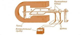
In Fig. Figure 1 shows a device diagram (model) of a simple alternating current generator.
A rectangular frame made of copper wire is mounted on an axis and rotates in the field of a magnet using a belt drive. The ends of the frame are soldered to copper contact rings, which, rotating with the frame, slide along the contact plates (brushes).
Figure 1. Diagram of a simple alternator
Let us make sure that such a device is indeed a source of alternating EMF.
Let us assume that a magnet creates a uniform magnetic field between its poles, i.e. one in which the density of magnetic field lines in any part of the field is the same. Rotating, the frame intersects the magnetic field lines, and an emf is induced in each of its sides a and b .
Sides c and d of the frame are non-working, since when the frame rotates they do not intersect the magnetic field lines and, therefore, do not participate in the creation of the EMF.
At any moment of time, the EMF arising in side a is opposite in direction to the EMF arising in side b, but in the frame both EMFs act in accordance and in total constitute the total EMF, i.e., induced by the entire frame.
This is easy to verify if you use the well-known right-hand rule to determine the direction of the EMF.
To do this, you need to position the palm of your right hand so that it faces the north pole of the magnet, and the bent thumb coincides with the direction of movement of that side of the frame in which we want to determine the direction of the EMF. Then the direction of the EMF in it will be indicated by the outstretched fingers of the hand.
For whatever position of the frame we determine the direction of the EMF in sides a and b, they always add up and form a total EMF in the frame. In this case, with each revolution of the frame, the direction of the total EMF in it changes to the opposite, since each of the working sides of the frame passes under different poles of the magnet in one revolution.
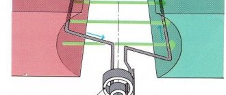
The magnitude of the EMF induced in the frame also changes, as the speed at which the sides of the frame intersect the magnetic field lines changes. Indeed, at the time when the frame approaches its vertical position and passes it, the speed of intersection of the force lines by the sides of the frame is greatest, and the largest EMF is induced in the frame. At those moments in time when the frame passes its horizontal position, its sides seem to slide along the magnetic lines of force without crossing them, and no emf is induced.
Thus, with uniform rotation of the frame, an emf will be induced in it, periodically changing both in magnitude and direction.
The EMF arising in the frame can be measured with a device and used to create a current in an external circuit.
Using the phenomenon of electromagnetic induction, it is possible to obtain an alternating emf and, therefore, an alternating current.
Alternating current for industrial purposes and for lighting is produced by powerful generators driven by steam or water turbines and internal combustion engines.
Graphic representation of direct and alternating currents
The graphical method makes it possible to visually represent the process of changing a particular variable depending on time.
The construction of graphs of variables that change over time begins with the construction of two mutually perpendicular lines, called the axes of the graph. Then, segments of time are plotted on the horizontal axis on a certain scale, and on the vertical axis, also on a certain scale, the values of the quantity whose graph is going to be plotted (EMF, voltage or current).
In Fig. 2 graphically shows direct and alternating currents. In this case, we plot the current values, and vertically up from the point of intersection of the O axes we plot the current values of one direction, which is usually called positive, and down from this point - in the opposite direction, which is usually called negative.
Figure 2. Graphical representation of DC and AC current
Point O itself serves simultaneously as the beginning of the countdown of current values (vertically down and up) and time (horizontally to the right). In other words, this point corresponds to the zero value of the current and the initial moment in time from which we intend to trace how the current will change in the future.
Let us verify the correctness of what is constructed in Fig. 2, and a graph of a constant current of 50 mA.
Since this current is constant, i.e., does not change its magnitude and direction over time, the same current values, i.e., 50 mA, will correspond to different moments in time. Therefore, at a time equal to zero, i.e. at the initial moment of our observation of the current, it will be equal to 50 mA. By plotting upward on the vertical axis a segment equal to the current value of 50 mA, we get the first point of our graph.
We must do the same for the next moment in time, corresponding to point 1 on the time axis, i.e., set aside a segment vertically upward from this point, also equal to 50 mA. The end of the segment will determine the second point of the graph.
Having done a similar construction for several subsequent moments in time, we will obtain a series of points, the connection of which will give a straight line, which is a graphical representation of a direct current of 50 mA.
Plotting a graph of the EMF variable
Let's now move on to studying the graph of the EMF variable. In Fig. 3 at the top shows a frame rotating in a magnetic field, and at the bottom is a graphical representation of the emerging EMF variable.
Figure 3. Plotting a graph of the variable EMF
Let's begin to uniformly rotate the frame clockwise and follow the progress of the change in the EMF in it, taking the horizontal position of the frame as the initial moment.
At this initial moment, the EMF will be zero, since the sides of the frame do not intersect the magnetic lines of force. On the graph, this zero EMF value corresponding to the moment t = 0 will be represented by point 1.
With further rotation of the frame, an emf will begin to appear in it and will increase in magnitude until the frame reaches its vertical position. On the graph, this increase in EMF will be depicted as a smooth upward curve that reaches its peak (point 2).
As the frame approaches the horizontal position, the emf in it will decrease and drop to zero. On the graph this will be depicted as a descending smooth curve. Consequently, during the time corresponding to half a revolution of the frame, the EMF in it managed to increase from zero to its maximum value and again decrease to zero (point 3).
With further rotation of the frame, an emf will again arise in it and will gradually increase in magnitude, but its direction will already change to the opposite, which can be verified by applying the right-hand rule.
The graph takes into account the change in the direction of the EMF in that the curve depicting the EMF intersects the time axis and is now located below this axis. The EMF increases again until the frame takes a vertical position. Then the EMF will begin to decrease, and its value will become equal to zero when the frame returns to its original position, having completed one full revolution. On the graph this will be expressed by the fact that the EMF curve, having reached its peak in the opposite direction (point 4), then meets the time axis (point 5).
This ends one cycle of changing the EMF, but if we continue to rotate the frame, a second cycle immediately begins, exactly repeating the first, which, in turn, will be followed by a third, and then a fourth, and so on until we stop the rotation framework.
Thus, for each revolution of the frame, the EMF arising in it completes a full cycle of its change.
If the frame is closed to any external circuit, then an alternating current will flow through the circuit, the graph of which will be the same in appearance as the EMF graph.
The wave-like curve we obtained is called a sine wave, and the current, EMF or voltage that changes according to this law are called sinusoidal.
The curve itself is called a sine wave because it is a graphical representation of a variable trigonometric quantity called sine.
The sinusoidal nature of current change is the most common in electrical engineering, therefore, when speaking about alternating current, in most cases we mean sinusoidal current.
To compare different alternating currents (EMF and voltages), there are quantities that characterize a particular current. These are called AC parameters.
Period, amplitude and frequency - parameters of alternating current
Alternating current is characterized by two parameters - period and amplitude, knowing which we can judge what kind of alternating current it is and build a current graph.
Figure 4. Sinusoidal current curve
The period of time during which a complete cycle of current change occurs is called a period. The period is designated by the letter T and is measured in seconds.
The period of time during which half of the complete cycle of current change occurs is called a half-cycle. Consequently, the period of change of current (EMF or voltage) consists of two half-cycles. It is quite obvious that all periods of the same alternating current are equal to each other.
As can be seen from the graph, during one period of its change the current reaches twice its maximum value.
The maximum value of an alternating current (emf or voltage) is called its amplitude or amplitude current value.
Im, Em and Um are generally accepted designations for the amplitudes of current, emf and voltage.
We first of all paid attention to the amplitude value of the current, however, as can be seen from the graph, there are countless intermediate values that are less than the amplitude value.
The value of alternating current (EMF, voltage) corresponding to any selected moment in time is called its instantaneous value.
i, e and u are generally accepted designations for instantaneous values of current, emf and voltage.
The instantaneous current value, as well as its amplitude value, can be easily determined using a graph. To do this, from any point on the horizontal axis corresponding to the moment of time we are interested in, we draw a vertical line to the point of intersection with the current curve; the resulting segment of the vertical straight line will determine the value of the current at a given moment, i.e. its instantaneous value.
It is obvious that the instantaneous value of the current after time T/2 from the starting point of the graph will be equal to zero, and after time T/4 its amplitude value. The current also reaches its amplitude value; but in the opposite direction, after a time equal to 3/4 T.
So, the graph shows how the current in the circuit changes over time, and that each moment in time corresponds to only one specific value of both the magnitude and direction of the current. In this case, the value of the current at a given moment in time at one point in the circuit will be exactly the same at any other point in this circuit.
The number of complete periods performed by the current in 1 second is called the frequency of alternating current and is denoted by the Latin letter f.
To determine the frequency of alternating current, i.e., to find out how many periods of change the current has completed within 1 second, it is necessary to divide 1 second by the time of one period f = 1/T. Knowing the frequency of the alternating current, you can determine the period: T = 1/f
The frequency of alternating current is measured in a unit called the hertz.
If we have an alternating current whose frequency is 1 hertz, then the period of such current will be equal to 1 second. And, conversely, if the period of current change is 1 second, then the frequency of such current is 1 hertz.
So, we have determined the parameters of alternating current - period, amplitude and frequency - which allow us to distinguish different alternating currents, emfs and voltages from each other and build their graphs when necessary.
When determining the resistance of various circuits to alternating current, use another auxiliary quantity that characterizes alternating current, the so-called angular or circular frequency.
The circular frequency is denoted by the letter ω and is related to the frequency f by the relation ω = 2πf
Let us explain this dependence. When constructing a graph of the variable EMF, we saw that during one full revolution of the frame, a complete cycle of EMF changes occurs. In other words, in order for the frame to make one revolution, i.e., turn 360°, it takes time equal to one period, i.e. T seconds. Then in 1 second the frame makes a 360°/T revolution. Therefore, 360°/T is the angle through which the frame rotates in 1 second, and expresses the speed of rotation of the frame, which is usually called angular or circular speed.
But since the period T is related to the frequency f by the ratio f = 1/T, the circular speed can be expressed in terms of frequency and will be equal to ω = 360°f.
So, we came to the conclusion that ω = 360°f. However, for the convenience of using the circular frequency in all kinds of calculations, the angle of 360° corresponding to one revolution is replaced by a radial expression equal to 2π radians, where π = 3.14. Thus, we finally obtain ω = 2πf. Therefore, to determine the circular frequency of alternating current (emf or voltage), the frequency in hertz must be multiplied by a constant number 6.28.
Source of information: “School for an electrician: electrical engineering and electronics”
Previous article Next article
High frequency currents
HDTV – this is their abbreviation; they are used for melting metals and hardening the surface of metal products. HDTV are currents with a frequency of more than 10 kHz. Induction furnaces use HDTV by placing a conductor inside a winding through which the HDTV is passed. Under their influence, eddy currents arising in the conductor heat it up. By adjusting the strength of the HDTV, the temperature and heating rate are controlled.
Interesting. The metal to be melted can be suspended in a vacuum using a magnetic field. It does not require a crucible (a special ladle for heating). This is how very pure substances are obtained.
Advantages of using HDTV in different cases:
- rapid heating during forging and rolling of metal;
- optimal temperature conditions for soldering or welding parts;
- melt even very refractory alloys;
- cooking in microwave ovens;
- Darsonvalization in medicine.
HDTV is obtained using installations that include an oscillating circuit or electric machine generators. The stator and rotor of the generators have teeth on the sides facing each other. Their mutual movement generates a pulsation of the magnetic field. The greater the product of the number of rotor teeth and its rotation frequency, the greater the output frequency.
Pulsation period and frequency
The frequency of alternating current may have another name - ripple. The pulsation period is the time of a single pulsation.
Cycle intensity
For an electrical network with a frequency of 50 Hz, the pulsation period will be:
T = 1/50 = 0.02 s.
If necessary, knowing this dependence, you can calculate the frequency from the cycle time.
The danger of multi-frequency charges
Both direct and alternating current at certain values pose a danger to humans. Up to 500 V the difference in safety is in the ratio 1:3 (42 V DC to 120 V AC).
At values above 500 V, this ratio levels out, with constant electricity causing burns and electrolysis of the skin, while changing electricity causes convulsions, fibrillation and death. Here the pulsation frequency is of great importance. The most dangerous frequency range is from 40 to 60 Hz. Further, with increasing frequency, the risk of damage decreases.
Effect of frequency on threshold current
The frequency of alternating electricity is an important parameter. It affects not only the operation of consumer electrical installations, but also the human body. By changing the frequency of electrical oscillations, it is possible to change technological processes in production and the quality of the generated energy.