Relevance of using electromagnetic brake
The frequency converter can hold the rotor stationary for some time by applying constant voltage to the motor. However, the electric drive is able to remain in this mode for only a few minutes, after which the windings begin to overheat. Therefore, in some cases, electric motors with brakes are used. First of all, this applies to lifting equipment - cranes, elevators, etc.
The electromechanical brake allows you to quickly stop the drive and keep it stationary for as long as desired. Typically, this need is dictated by considerations of safe operation of the equipment.
Motor braking
Production processes involving the operation of equipment equipped with AC or DC electric motors require periodic shutdowns. However, after disconnecting the supply voltage from the electric motors, their rotors continue to rotate by inertia and stop only after a certain period of time. This stopping of the electric motor is called freewheeling.
For electric motors that operate with frequent starts and stops, free coasting is not suitable. To reduce the time required to completely stop rotor rotation, forced braking is used. Electric motor braking methods are divided into mechanical and electrical.
Mechanical braking
Stopping engines with this method of braking is carried out thanks to special pads on the brake pulley. After turning off the supply voltage, the brake pads are pressed against the pulley under the influence of springs. As a result of the friction between the pads and the pulley, the kinetic energy of the rotating shaft is converted into thermal energy, which leads to its complete stop. After applying voltage, the electromagnet (YB) releases the brake pads, and operation of the electric motor continues in normal mode.
Depending on the electrical braking circuit, the kinetic energy of the rotating rotor can be transferred to the network or to a battery of capacitors, and also converted into heat, which is absorbed by the windings of the electric motor or special rheostats.
Dynamic motor braking
This stopping circuit is suitable for three-phase electric motors with both squirrel cage and wound rotor types.
Dynamic braking of an electric motor with a squirrel-cage rotor is carried out by disconnecting the stator windings from the three-phase alternating current supply network and switching two of them through a system of contactors and relays to a source of rectified direct voltage.
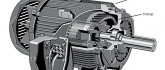
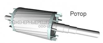
The stator windings, after applying constant voltage to them, generate a stationary magnetic field, under the influence of which in a short-circuited “squirrel cage”
rotating rotor, an electric current begins to be induced, causing the appearance of a tomosive moment. The direction of this moment is opposite to the direction of rotation of the stopping shaft. After stopping the engine, the supply of direct voltage to the stator windings is stopped.
In motors with a wound rotor, the amount of braking torque can be adjusted using additional resistances, which are used as starting resistors.
Back braking
Braking of an asynchronous electric motor using the back-to-back method is carried out by reversing the motor without disconnecting from the supply network.
Braking control is performed by the speed control relay. In operating mode, the relay contacts are closed. After pressing the “STOP” button (SBC), the group of contactors switches two phases, changing the order of their alternation. As a result, the stator's magnetic field begins to rotate in the opposite direction, which causes the rotor to slow down. When the rotation speed becomes close to zero, the speed control relay opens its contacts and the supply voltage is stopped.
Capacitor braking of electric motors
This method, also called self-excited braking, is applicable only to electric motors with a squirrel-cage rotor.
After the supply voltage is stopped, the electric motor rotor continues to rotate by inertia and generates an electric current in the stator windings, which first charges the capacitor bank, and after accumulating the rated charge returns to the windings. This leads to the occurrence of a braking torque, the magnitude of which depends on the capacity of the capacitor banks connected to each phase in a star or delta configuration. Self-excited braking is used on engines with a large number of starts and stops, since the amount of energy loss in the engines with such a stopping scheme is minimal.
Regenerative braking
Regenerative or otherwise regenerative braking of asynchronous electric motors is used in practice as preliminary braking, as well as when lowering loads with cranes of all types or passenger and freight elevator cabins.
Braking of an asynchronous electric motor in regenerative mode occurs when the rated rotor speed exceeds its synchronous frequency. The engine begins to generate electrical energy and send it to the power supply network, resulting in the creation of a braking torque. This stopping method is used for multi-speed motors by gradually switching from a higher rotor speed to a lower one. Thus, at a certain moment, the speed rotating under the influence of the inertia of the shaft will be greater than the synchronous frequency corresponding to the connected number of stator poles. In addition, a regenerative braking circuit is used for motors connected to frequency converters. To do this, it is enough to reduce the frequency of the supply voltage.
Stopping DC motors (DCM)
Braking of DC electric motors is carried out by counter-switching and in a dynamic way.
Dynamic braking
This braking circuit is used for motors with independent excitation.
After pressing the “Stop” button (SB1), the armature windings are disconnected from the supply network and reconnected to the braking resistor. In the windings of the armature, rotating by inertia in a stationary magnetic field, a direct current is induced, which, passing through the winding wires of the resistor, is converted into thermal energy.
Back braking
The reverse connection method is based on changing the polarity of the voltage connected to the windings of the inductor or motor armature. This results in a change in the polarity of the magnetic flux or the direction of the current induced in the armature. Thus, the direction of the torque is reversed, which causes a braking effect. The speed of rotation of the armature is controlled by a speed relay, which cuts off power to the armature when it approaches zero. To place an order, call the managers of the Kabel.RF® company by phone or send a request by email indicating the required electric motor model, purposes and operating conditions. The manager will help you choose the right brand, taking into account your wishes and needs.
Design
The design of the electromagnetic brake includes:
- electromagnet with coil
- brake disc with linings
- pressure springs
- clamping torque adjustment system
In most cases the brake is normally braked. This means that the motor rotor is fixed when there is no power to the brake. When power is applied to the coil, the brake pads are released and the rotor is released.
How to choose an electromagnetic disc brake
Motors with electromagnetic brakes are used in industry in production processes that require a regulated stop of the equipment drive or to ensure personnel safety.
Motors are usually equipped with DC brakes, operating through a rectifier located in the motor terminal box. However, there are motors on which AC brakes are installed; this type of equipment provides the least delay in the operation of the electromagnetic brake and the rapid increase in braking torque. In this article we will analyze the operating principle of an electromagnetic DC brake and the ability to independently select a brake on our website to replace the one installed on your engine. SDZ1 and DZS1 brakes are presented on our website. In some cases, they differ only in their dimensions, sometimes in the braking torque and in the dimensions for attachment to the bearing shield of the electric motor.
Electromagnetic brake working principle
1. Electromagnet housing 2. Brake coil 3. Spring 4. Electromagnet armature 5. Release handle 6. Adjusting bolt 7. Fastening bolt 8. Brake disc 9. Toothed clutch 10. Rear bearing shield.
Q – air gap.
When the power from the electric motor is turned off, the electric brake is activated. The mechanism clamps the gear coupling, which, in turn, stops the rotation of the motor shaft.
Installation methods
The brake can be built into the engine design or be a separate device. The most preferable is a built-in brake, which is located on the rotor axis. This design is compact and easy to use.
If the use of a motor with a built-in brake is for some reason impractical, a separate brake is used. Its main advantages are the possibility of installation anywhere in the drive (for example, on the gearbox axis), the dimensions and method of mounting the device are not tied to the engine design.
Design Features
Electric motors with a built-in electromagnetic brake have the same design regardless of the voltage type. The brake consists of three main elements:
- an electromagnet, which is a steel case in which one or more coils are placed;
- an armature with an antifriction surface with which the brake disc is in contact. It acts as an actuating electromagnetic brake;
- brake disc, which is the active part of the brake and is equipped with friction linings without asbestos. It rides on a gear sleeve attached to the brake drive shaft or motor shaft.
To order an electromagnetic brake, you need to contact technical specialists by phone listed on the website or by filling out the feedback form. The manager will conduct a free consultation, answer all your questions and help you make your choice.
Brake Power Supply Methods
An electromechanical brake can have dependent or independent power supply. In the first case, its coil is powered from the same source as the motor windings. In this case, the brake must be normally braked so that in the event of a power failure it locks the rotor.
An independently powered brake can be controlled more flexibly, but requires a separate power circuit that must be synchronized with the motor power supply. The most universal brake of this type is a two-winding brake. The coil in it consists of two windings. The short winding turns on the brake, and the long winding (with less current) holds it in place.
If the motor is powered from the inverter, it is necessary to pay attention to the parameters of the electromechanical brake in the converter settings. Ideally, the drive and brake motor should be manufactured by the same manufacturer.
Operating principle of an industrial motor brake
The above-mentioned inhibition of the electric motor in a switched off or stopped state is determined by the fact that the pressure of springs in the form of plates on the armature acts on the brake disc. The brake torque is determined by the area of the linings and the force with which they are pressed. Therefore, the shaft stops. When the coil is supplied with current, it creates a magnetic field, which in turn attracts an armature, which releases the brake disc. After this, the electric shaft of the motor rotates. Manual braking effectively copes with starts and stops.
Maintenance of the electromechanical brake
Since the brake is an electromechanical device subject to wear, it requires regular maintenance. The brake clearance must be checked regularly to the value recommended by the manufacturer. The gap may decrease or increase, and may also have distortions due to wear of the brake pads or springs, or damage to the fasteners.
Since the brake is subject to shock and vibration when the engine is running, care must be taken to secure the mounting nuts and studs. It is also recommended to use thread locker.
For repair and maintenance of equipment, it is usually possible to manually release the brakes using a special lever. This function must be used carefully to avoid damage to equipment and personal injury.
The braking torque of the electromagnetic brake can be adjusted within certain limits.
Back braking
Back-up braking circuit
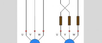
In practice, the opposition regime can be organized in several different ways. The classic method is to use a pair of magnetic starters connected in a reverse circuit. In this case, a quick stop of the unit is carried out by changing the position of the phases (counter-switching).
The main starter KM2 disconnects the motor M from the network. After this, the parallel starter KM1 turns on the engine again, changing the extreme phases in places, that is, forcing it to rotate in the opposite direction. To prevent excessive overheating, additional resistance can be introduced into the circuit. Also, a counter-connection circuit can be implemented if the engine is used as a brake for a load.
Operating mode
It is recommended to use an electromechanical brake to brake the engine at a non-zero speed only in emergency cases, since in this mode the wear and heating of the brake pads sharply increases. The circuit must be designed in such a way that the brake is a parking brake, that is, it is activated only at zero speed. For this purpose, the inverter has a special output. In this mode, the brake pads hardly wear out and have a long service life.
Frequent use of the braking function not only causes wear and tear, but also heats up the brake. If the technological process does not allow reducing the number of braking times per unit of time, additional airflow for the brake should be provided, as well as a more responsible approach to its maintenance.
Other useful materials:
Maintenance of frequency converters Methods of protecting electric motors Advantages and disadvantages of an asynchronous motor
What is dynamic braking?
At this point, a logical question may arise: why invent something if you can disconnect the engine from the mains and it will stop on its own? This is undoubtedly true, but given the high rotation speed and mass-centering characteristics, it will take some time until the rotor comes to a complete stop. This period is called free run and everyone observed it in childhood, launching a simple spinning top. However, if the operation of the equipment involves frequent use of starters, then this mode leads to an obvious loss of time.
To quickly stop, braking modes are used, which involve the transformation of mechanical (in this case, kinetic) energy artificially. Everyone distinguishes two main types of inhibition, which are then divided into subtypes:
- Mechanical. The engine shaft communicates physically with the brake pads, resulting in friction, rapid stopping and heat generation,
- Electric. An asynchronous motor is stopped by converting the connection circuit, as a result of which mechanical energy is first transformed into electrical energy. Then there are two possible options for its consumption, depending on the circuit: either excess electricity is released into the backup circuit of the network, or it is transformed into heat due to heating of the windings and resistance.
Dynamic braking of an asynchronous motor is of the electrical type, since during the process the stator winding is disconnected from the AC network (two of the three phases) and transferred to a closed DC circuit. In this case, the magnetic field in the stator is converted from rotating to stationary. An EMF will still be induced in the rotor, but the torque will be directed in the opposite direction, which leads to braking.
The main advantage of this method of braking is the ability to smoothly control the braking torque (by changing the voltage or resistance) and carry out an accurate stop.
