When using electrical appliances, there is always a risk of electric shock. This probability comes from the properties of an ordered flow of charged particles: it passes through that section of the circuit in which the resistance has a minimum value. At various times, manufacturers of devices and components tried to combat this and protect people from the harmful or even fatal effects of current. But in the end, grounding remains the simplest and most reliable.
Grounding is used in industrial enterprises and country houses. It plays a special role in the case when the power of the device exceeds critical values. A person only needs to receive a blow with a force of 0.1 ampere to be guaranteed to die. Also, do not forget that even working equipment can be a source of danger. This can happen due to lightning and some other reasons. Therefore, the issue of installing grounding should be approached responsibly and take into account all the nuances.
Grounding tests
There is a lot of controversy regarding the installation of grounding and the norms for the flow of current through it. But experts agree absolutely unanimously on one thing - a specialist should check the quality of the installed circuit. This procedure will allow you to be confident in the correct installation of grounding in the house and will protect yourself and your loved ones from the dangerous effects of electric current. Tests are carried out both in enterprises where high-power generators and engines often operate, and in private homes - measuring ground resistance is done in the same way.
There are two main types of tests: acceptance and operational. The first ones are carried out in cases where the installation (or section of the network) is already completely installed and ready for immediate use. Before measuring the grounding resistance, it is determined whether the circuit is ready to absorb currents if necessary and whether its parameters meet the stated requirements. Among other things, it is necessary to regularly monitor that the installed grounding does not lose its properties over time. To do this, operational tests are carried out - a specialist checks a finished section of the network that is already in use. To carry out such a procedure, you need to free the network from consumers, so the whole process requires a little preparation.
What is the frequency of measurements?
Before measuring the grounding resistance in one way or another, it is important to take into account the requirements of the PUE regarding the frequency of these tests. According to the main provisions of this document, they can be carried out in the following forms:
- routine examinations;
- extraordinary inspections;
- launch tests.
The frequency of each of these types of inspections is determined by the goals that they set for themselves. The frequency of inspections of the insulation resistance of station equipment is usually consistent with the inspection of the circuit breaker itself. Let's look at their different types in more detail.
Scheduled checks
The timing of planned activities is stipulated by instruction RD-34.22.121-87, as well as the requirements of the PUE. From these documents you can find out what is the frequency of visual inspection of visible parts of grounding devices, which according to them is organized at least once every six months. In addition, from the same standards it follows that at least once every 12 years, inspections of the structure must be carried out with the opening of the soil around it. Measurement of the resistance of grounding loops according to the same documents should be carried out at least once every 6 years.
Persons authorized to do so by the relevant authorities are responsible for conducting such inspections. The owner of a private house must fill out an application for them in advance with subsequent payment. Upon completion of the tests, he is obliged to provide the local energy service with a protocol for measuring the contact resistance between the elements of the closed circuit.
Extraordinary
Extraordinary measurements of circuit parameters should be carried out in the following emergency situations:
- After making changes to the design that are not provided for by the design, but affect the resistance to current flow (measurement of grounding in a private house should be carried out when moving it to another place).
- After emergency destruction and subsequent restoration of the ZK.
- Upon completion of the repair work.
The frequency of their holding is not regulated for obvious reasons.
Starting or introductory
Start-up or introductory grounding checks and resistance measurements are organized immediately after the installation of the protective circuit is completed (that is, on the eve of its delivery to the local energy service representative). To do this, you will need to invite a specialist from an electrical laboratory or other organization licensed to conduct such tests.
Based on the results of the inspection, an acceptance certificate is issued, which is the basis for the subsequent commissioning of the device and confirmation that all supply lines in private houses are grounded.
Test conditions
When organizing grounding testing activities, it is important to pay attention to the conditions in which they are supposed to be carried out. They must be taken into account at the test preparation stage, and upon completion they must be entered in a special journal. According to the requirements of current regulations (PUE, in particular), for this it is advisable to choose the summer season with sunny, dry weather, which allows you to obtain results that are closest to reality. This is explained by the fact that at such a time the soil is maintained in a fairly dry condition, corresponding to the actual operating conditions of the protective structure.
When carrying out control measurements of permissible resistances in damp autumn weather, for example, the results obtained will be significantly distorted. This is explained by the fact that soil saturated with moisture significantly increases the conductivity of the soil. In order to avoid all these difficulties and get a value close to the real value, the easiest way is to use the services of professionals. To do this, you must contact a special electrical laboratory that has a license to carry out the relevant work.
Upon arrival at the site, specialists will identify all factors and organize testing of protective equipment in accordance with the requirements of current regulations. Upon completion of the entire test cycle, they will also draw up a grounding resistance measurement protocol, a sample of which is presented below.
Protocol for testing grounding resistance
How is grounding measured?
To measure this value, an ohmmeter is used - a device that changes resistance. In this case, devices for determining grounding resistance must have certain characteristics. The most important thing: very low input conductivity. The measurement range of such devices is extremely small: usually it ranges from 1 to 1000 Ohms. The measurement accuracy in analog instruments does not exceed 0.5–1 Ohm, and in digital instruments - up to 0.1 Ohm.
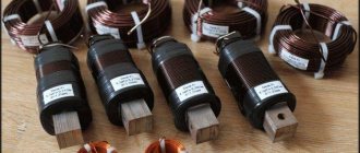
Despite the widespread spread of Chinese and European devices, the most popular remains the M416, developed in the USSR. The device has four measurement ranges: from 0 to 10 Ohms, from 0.5 to 50, from 2 to 200 and from 100 to 1000. The device runs on three AA batteries. Despite this, it is difficult to call it mobile - the dimensions of the case are not very comfortable.
A more advanced version is F4103 - an industrial ohmmeter with a high input resistance. It is even less transportable, but has a greater number of measurement ranges. A big plus of such a device: it works with a huge range of signals (from direct and pulsating current to alternating current with a frequency of 300 Hz). The user will also be pleased with the operating temperature range: from –25 to 55 degrees Celsius.
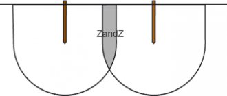
Earth resistance measurement (three-point method)
Earth resistance measurement (three-point method)
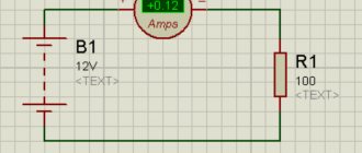
In this method, the C1 and P1 terminals of the ground tester are shorted to each other and connected to the ground electrode (pipe) being tested. Terminals P2 and C2 are connected to two separate ground driven spikes. These two peaks are kept in the same line at a distance of 25 meters and 50 meters, due to which there will be no mutual interference in the field of individual spikes.
If we rotate the generator handle at a certain speed, we get direct resistance to the ground on the scale. The length of the spike in the ground should not exceed 1/20 the distance between two spikes. Resistance should be checked by increasing or decreasing the distance between the tester electrode and the spikes by 5 meters.
Typically, the length of the wires should be 10 and 15 meters or in proportion to 62% of D.
Assume the distance of the Current Spike from the ground electrode is D = 60 feet. Then the distance from the potential spike will be 62% of D = 0.62D, i.e. 0.62 x 60ft = 37ft.
How to measure resistance
There are two documents that regulate the standards for grounding resistance in a circuit and other indicators. The first is the PUE (Electrical Installation Rules), which are relied upon when carrying out acceptance control. Operational measurements must comply with the Rules for the Technical Operation of Consumer Electrical Installations (PTEEP).
In both sets of rules, there is a division of circuits into several types - these must be taken into account before measuring ground resistance. They differ depending on the voltage used in the network and the type of circuit. There are three types of circuits:
- For substations and distribution points where the voltage does not exceed 1000 volts (regardless of whether the network uses alternating current or direct current).
- For overhead power lines (power lines) that transmit current with a voltage of less than 1000 volts.
- For electrical installations with the same maximum permissible voltage used for industrial or domestic purposes.
Checking the grounding of outlets
If you bought a house or apartment, and all the electrical parts in the room were already installed before you, how to check the grounding in the outlet?
To begin, we suggest you perform a visual inspection. Disconnect the input circuit breaker for the apartment and disassemble one socket. It must have a corresponding terminal to which the grounding conductor is connected; as a rule, it is yellow-green in color. If all this is present, then the outlet is grounded. If you find only two wires - brown and blue (phase and neutral), then the outlet does not have a protective ground.
At the same time, the presence of a yellow-green conductor does not mean that the grounding is working properly.
The efficiency of the circuit can be determined with a special device, which no electrician can do without, a multimeter. The algorithm for this check is as follows:
- In the distribution panel, turn on the input circuit breaker, that is, there must be voltage in the sockets.
- Set the device to voltage measurement mode.
- Now you need to touch the phase and neutral contacts with the probes of the device and measure the voltage between them. The device should display a value of about 220 V.
- Make a similar measurement between the phase and ground contacts. The measured voltage will differ slightly from the first value, but the very fact that some numbers appear on the screen indicates that there is grounding in the room. If there are no numbers on the device screen, it means that there is no ground loop or it is in a faulty condition.
When you don’t have a multimeter, you can check the operation of the circuit with a DIY tester. You will need:
- cartridge;
- bulb;
- wires;
- limit switches.
Electricians call such a tester a “control light” or “control” for short. Touch one end probe to the phase contact, and the second touch the zero one. The light should light up. Now move the limit switch with which you touched the zero to the antenna of the grounding contact. If the light comes on again, it means the ground loop is in working order. The lamp will not light if the protective ground is not working. A weak glow will indicate poor condition of the circuit.
If an RCD is connected to the circuit being tested, then during the testing actions it may operate, which means that the grounding loop is operational.
Note! It may be that when the limit switches touch the phase and ground contacts, the lamp does not light up. Then try to move the probe from the phase contact to the neutral one; perhaps, when connecting the socket, the zero and phase were confused.
Ideally, you should begin checking actions by using an indicator screwdriver to determine the phase contact in the switching device.
This method is clearly shown in the video:
The following indirect situations may also indicate a faulty or unconnected ground loop:
- the washing machine or water heating boiler is electrocuted;
- There is noise in the speakers when the stereo is on.
Standards for each type
In order to understand what regulatory and operational indicators should be for each type:
- For electrical installations. Ground resistance measurements should be carried out in close proximity to the substation. Depending on the load, this figure can be 60, 30 or 15 Ohms. It is also worth considering natural grounding electrodes - for them these values should be 8, 4 or 2 Ohms, respectively. All three quantities depend on the network voltage. 60 and 8 Ohms are allowed for a single-phase network of 200 volts. 30 and 4 Ohms - for three-phase with a voltage of 380 volts. The minimum values (15 and 2 Ohms) are for 660 volts. During operation, the resistance of the ground loop should also not fall below the values described in the paragraph above.
- For a distribution point or substation. For installations with voltages above 100 kilovolts (100 thousand volts), the grounding conductivity during the commissioning of the network and during its operation also remains unchanged and is 0.5 Ohm. In this case, the mandatory requirements for testing are a solid grounding type and connected to a neutral circuit. There are also standards for less powerful installations, in which the voltage lies between 3 and 35 kilovolts. In this case, you need to divide 250 by the calculated ground fault current - the resulting value will be the required resistance in Ohms. The indicator, according to PTEEP, should not exceed 10 Ohms in any case.
- For overhead power lines. It is calculated depending on the conductivity of the soil on which the power line supports stand:
- for soil with a resistivity of less than 100 Ohms per meter - 10 Ohms;
- with a resistivity of 100...500 Ohms per meter - 15 Ohms;
- with a resistivity of 500...1000 Ohms per meter - 20 Ohms;
- with a resistivity of 1000...5000 Ohms per meter - 30 Ohms.
For power lines with a current voltage of less than 1000 volts - up to 30 Ohms (for supports with lightning protection). Otherwise, the resistance should be 60, 30 or 15 ohms for networks with voltages up to 660, 380 or 220 volts, respectively.
Grounding - what is it (definitions)
In conclusion, we present some common definitions of grounding. Grounding is an intentional electrical connection of any point in the network, electrical installation or equipment with a grounding device. In electrical engineering, with the help of grounding, protection from the dangerous effects of electric current is achieved by reducing the touch voltage to a value that is safe for humans and animals.
Another definition. Grounding is the connection of the housings of all electrical appliances in the house with the ground through the circuit of the grounding device. For this purpose, there is a separate core in the entire system, including the cable of the electrical appliance. It goes from the sockets through the shield to the grounding loop, which is dug into the ground. An appliance connected to such an outlet is protected. That is, if it is faulty and voltage appears on its metal parts, the excess current will go into the ground. In the worst case, a small, harmless charge will remain on the case. When touched, it will feel like a slight tingling sensation.
As you can see, they talk about safety and a slight tingling sensation everywhere. Why are our numbers not so optimistic? Because our examples do not take into account additional protective measures to equalize and equalize potentials. Potential equalization is the electrical connection of conductive parts to achieve equality of their potentials. Potential equalization is the reduction of potential difference (step voltage) on the surface of the earth or floor using protective conductors laid in the ground, in the floor or on their surface and connected to a grounding device, or by using special earth coatings. And this is a separate topic for consideration.
Therefore, when reading such definitions about protective grounding, keep in mind that just a grounding loop is not 100% protection. And if the floor on which you are standing does not have the potential of a phase pierced to the body, then you will not get away with a slight tingling sensation when you touch the body of the device if the automatic power off is not triggered. Everything will be much worse.
What does grounding resistance depend on?
As mentioned above, current has one important feature - it flows through that part of the circuit that least resists it. The resistance value itself depends on many factors:
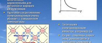
- Material . A number of materials have a special (atomic) structure, which implies the presence of a large number of free electrons. If such materials are exposed to any magnetic field or connected to a power source, they easily conduct electric current. For the most part, this statement applies to metals. Other materials have no free electrons and their resistance to current is extremely high. If the voltage (the force “pushing” the electrons) is below the permissible value, then the conductivity will be zero or extremely small values. If the indicator is exceeded, a breakdown will occur and the resulting deposit will have the properties of a conductor. It is logical that only representatives of the first group of materials can be grounding materials - it is this group that provides the minimum resistance.
- Its temperature . Temperature determines how quickly electrons move within a material. Therefore, the lower it is for a conductor, the better it conducts charge. The inverse dependence is also in the nature of a direct proportion - after its increase, its resistance will fall. The calculation of grounding resistance must be made taking this parameter into account.
- Presence of impurities . The main part of the conductors is made of copper. Old wires were made of aluminum, but such solutions have several disadvantages. Unfortunately, cables and wires made of this material overheat and melt faster, and the resistance of industrially mined aluminum is lower than that of copper. Chemically pure metal is the best conductor, surpassing even silver in conductivity. The thing is with impurities: they have much higher resistance values. The same point should be taken into account when calculating grounding.
It is clear that ideally the resistance should be minimal - for this you need to use a copper circuit with a large cross-section. But the fact is that copper oxidizes quickly, and the cost of such a solution will be extremely high. Consequently, standards have been developed for the minimum grounding threshold. This indicator does not need to be exceeded so that at the right moment under load the circuit fulfills its assigned function and discharges the charge to the ground.
Contact resistance measurements
When measuring ground loop parameters, special attention is paid to the so-called “transition” zones formed over the entire area of direct joints of structural elements (including their contact with the soil and the soil itself). For these sections, the concept of “transition resistance” is introduced, which significantly affects the total value. All the measurement methods discussed above also concerned this part of the total system resistance (with the exception of the resistance of the material of the grounding conductors and pins).
By its magnitude, one can judge the speed at which a dangerous charge flows into the ground, as well as the obstacles encountered along the way. In existing systems, this component makes a significant contribution to the formation of the overall indicator for the entire ZK.
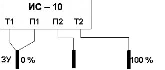
How to measure contact resistance
Before measuring grounding in transition zones, you will need to prepare a special device called a milliohmmeter. To carry out these tests, any other grounding measuring device from the same series will do (sometimes M-416 universal devices are used for this). Regardless of the type of device selected, only certified measuring equipment that has passed state verification should be used for these purposes. Otherwise, the measurements taken on the device will not be considered to comply with current standards and GOSTs.
When carrying out such measurements, the device selected as a measuring device with a charged power battery is connected with its clamp terminals on both sides of the controlled connection. Regardless of the type of circuit elements, the transition resistance between them should not exceed 0.05 Ohm. If a measurement of the grounding transient resistance carried out using this method gives an unsatisfactory result, the operation of the installation is stopped until the causes are identified and eliminated. The transient conductivity measurement diagram is shown in the photo below.
Contact resistance measurement circuit
Before checking the ground loop, you need to familiarize yourself with the existing methods for calculating it. In the vast majority of cases, they come down to simple calculations using Ohm’s law (by dividing the measured voltage by the current readings taken in the corresponding circuit).
Additional information: Before calculating the grounding resistivity, it is important to take into account all links in the emergency current flow chain, including contact zones.
The resulting result fully characterizes the design for its compliance with the standardized indicators.
How often is it measured?
The timing of checking the grounding of electrical installations is established in accordance with the following regulatory requirements:
- Visual inspections – every six months.
- Checking the quality of connections of metal elements at their joints - once a year.
Unscheduled checks of the contact resistance of the ground electrode are also possible, which are usually carried out after restoration of the circuit, as well as when serious adjustments are made to its design. Tests can also be carried out when a newly launched grounding system is put into operation.
When organizing regular or extraordinary inspections, it is necessary to be guided by the general provisions for calculating grounding resistivity.
Calculation formula
Formula for calculating the grounding resistance of a single vertical ground electrode:
where: ρ - soil resistance per unit length (Ohm×m) L - length of the ground electrode (in meters) d - width of the ground electrode (in meters) T - distance from the ground surface to the middle of the ground electrode (in meters)
For electrolytic grounding:
Formula for calculating the grounding resistance of a single horizontal electrode with the addition of a correction factor:
Where:
ρ—soil resistance per unit length (Ohm×m); L is the length of the ground electrode (in meters); d is the width of the ground electrode (in meters); T is the distance from the earth’s surface to the middle of the ground electrode (in meters); C is the relative content of electrolyte in the surrounding soil.
The C coefficient varies from 0.5 to 0.05. Over time, it decreases, as the electrolyte penetrates into the soil to a larger volume, while increasing its concentration. As a rule, it is 0.125 after 6 months of leaching of electrode salts in dense soil and after 0.5–1 month of leaching of electrode salts in loose soil. The process can be accelerated by adding water to the electrode during installation.
The calculated electrical resistivity of the soil (Ohm×m) is a parameter that determines the level of “electrical conductivity” of the earth as a conductor, that is, how well the electric current from the ground electrode will flow in such an environment.
This is a measured value that depends on the composition of the soil, the size and density of its particles adhering to each other, humidity and temperature, and the concentration of soluble chemicals in it (salts, acidic and alkaline residues).
Method for constructing a grounding pit
- Excavation on the ground for normal ground. The pit size is 1.5MX 1.5MX 3.0 M.
- Use 500mm X 500mm X 10mm GI Plate or Bigger for more ground contacts and reduced ground resistance.
- Make a mixture of charcoal powdered salt and sand in equal proportions
- Charcoal Powder is used as a good conductor of electricity, anti-corrosion, rust proof for GI plate for long life.
- The purpose of coal and salt is to constantly moisten the soil.
- The salt seeps in and the coal absorbs the water, keeping the soil moist.
- Maintenance should always be done by watering the soil holes in the summer to keep the soil of the hole moist.
- Charcoal is made from carbon, which is a good conductor that minimizes resistance to earth.
- Using salt as an electrolyte to form conductivity between GI Plate Coal and Earth with moisture.
- Sand is used to create porosity to cycle water and moisture around the mixture.
- Place a GI plate (GROUND PLATE) measuring 500mm X 500mm X 10mm in the middle of the mixture.
- Use Double GI Strip 30mm X 10mm to connect the GI plate to the Earthling system.
- It is better to use 2.5" diameter GI tubing with a flange on the top of the GI pipe to cover the GI strip from the EARTH PLATE to the top flange.
- Cover the top of the GI pipe with a triple joint to avoid the pipe being jammed with dust and dirt, and use water through this pipe at the bottom of the earth plate from time to time.
- Maintain a resistance of less than 1 ohm from the PART EARTH conductor to a distance of 15 meters around the PIT GROUND with another conductor run on the ground at least 500mm deep.
- Check the voltage between the grounding conductors to the neutral of the mains supply 220 V AC 50 Hz, it should be less than 2.0 V.
Results and conclusions
Grounding is an important element of an electrical circuit that provides protection against short circuits, electric shock or lightning strikes in one of its sections. The key indicator here is resistance: the lower it is, the more current the circuit will “carry” and the lower the likelihood of a serious shock or damage to the equipment. Grounding resistance is regulated by two documents: PUE and PTEEP. The first is used to receive a newly commissioned section of the network, the second is used to control an already operating section.
Control standards that are designed to check the quality of grounding and the operation of the circuit under full load conditions cannot be neglected. Procedures are carried out both immediately after the creation of the chain and during its use. The frequency of checks depends on the load on the network and the purpose for which the circuit is used. The norms of resistance are not different at all. There are three types of standards: for power lines, transformers and electrical installations. As the operating voltage increases, the maximum resistance value increases exponentially. A number of specific indicators are also taken into account (for example, soil conductivity). Based on it, you can obtain the maximum regulated resistance.
The main ways to increase the efficiency of the ground electrode is to use different conductor configurations. The key task is to maximize the area of direct contact of the circuit with the ground. For this, one or more conductors are used. In the latter case, they can be connected both in series and in parallel.
Also, to measure the resistance of the grounding loop, it is important to know the correction factors - for example, when calculating the minimum permissible grounding resistance, the specific content of the material in the soil and the re-grounding resistance are also taken into account. To obtain this indicator you need to use special equipment.
Protective grounding and other measures for indirect contact
The rules for the protection of electrical installations state that to protect against electric shock in the event of insulation damage, the following protective measures for indirect contact must be applied individually or in combination:
- Protective grounding.
- Automatic power off.
- Potential equalization.
- Potential equalization.
- Double or reinforced insulation.
- Ultra-low (low) voltage.
- Protective electrical separation of circuits.
- Insulating (non-conductive) rooms, zones, areas.
As you can see, there is such a thing as protective grounding during indirect contact. We are not interested in other protection measures, except for automatic power off, in this topic. And in addition to protective grounding, there is also working grounding.
Therefore, at this stage, let’s define the terminology:
- Grounding is an intentional electrical connection of any point in the network, electrical installation or equipment with a grounding device.
- Protective grounding is grounding performed for electrical safety purposes.
- Working (functional) grounding - grounding of a point or points of live parts of an electrical installation, performed to ensure the operation of the electrical installation (not for electrical safety purposes).
- Indirect touch is electrical contact of people or animals with exposed conductive parts that become energized when the insulation is damaged.
We are more interested in electrical safety. Therefore, when talking about how grounding works, we will consider protective grounding paired with automatic power off. But you need to understand that grounding, in addition to protective, can also be operational.
Requirements for grounding devices
a) Electrical installations with voltages above 1000 V with high ground fault currents
. According to the PUE, the resistance of the grounding device in these electrical installations should not exceed 0.5 Ohm. However, limiting the resistance of the grounding device alone does not provide acceptable touch and step voltages for ground fault currents of several kiloamperes.
Fig.8-11. Potential equalization using additional equalizing conductors with a contour grounding system
For example, with a short circuit current of 6 kA, the grounding device will have a voltage of 3 kV. Therefore, in addition to limiting the resistance of the grounding device, the following measures are also provided:
1) fast shutdown for ground faults;
2) equalization of potentials within the territory in which the electrical installation is located and on its borders.
To equalize potentials on the territory of an electrical installation, a grid of equalizing conductors should be laid at a depth of 0.5-0.8 m (Fig. 8-11). Longitudinal conductors are laid parallel to the axes of the equipment at a distance of 0.8 - 1 m from the foundations or bases of the equipment and are connected to each other over the entire area by transverse conductors with a pitch of no more than 6 m. To improve alignment at the boundary of the contour, the outermost conductors of the mesh, from which greater flow occurs current into the ground, laid at a depth of about 1 m.
Potential equalization should also be carried out at the entrances and entrances to the territory of the electrical installation by laying two additional strips with gradual deepening; at a distance of 1 and 2 m from the ground electrode at a depth of 1 and 1.5 m, respectively.
When placing an electrical installation on a sufficient area, the distance from the boundaries of the grounding conductor to the fence of the electrical installation must be at least 3 m, and the fence in this case is not grounded. In areas frequently visited by personnel and at entrances and exits, it is advisable to install paths coated with low-conductivity asphalt or gravel.
In order to prevent the potential from being carried outside the territory of an electrical installation with a large ground fault current, it is prohibited to supply power to receivers located outside the territory of the electrical installation from transformers with a grounded neutral at voltages of 380/220 or 220/127 V located within the territory of the electrical installation. If necessary, such receivers are powered from transformers with an isolated neutral.
To prevent potential carryover, rail tracks entering the territory of an electrical installation are not connected to the grounding circuit of the electrical installation, and at the exit from the electrical installation, the rails are grounded at several points. Since the rails have zero potential, the possibility of a person coming under significant step voltage within the electrical installation when he touches the ground with one foot and the rail with the other must be excluded. This possibility is excluded when the railway track is embanked with coarse crushed stone, pebbles, and shell rock, which have low conductivity.
If the ground electrode is not located inside the fenced area, it can be expanded beyond the electrical installations with mandatory potential equalization at the boundary of the circuit by gradually deepening the outermost conductors of the grid. In this case, the metal parts of the fence and the reinforcement of the reinforced concrete fence posts must be connected to the ground electrode.
When locating electrical installations with a large ground fault current near the workshops of industrial enterprises, the following measures must be taken:
1) all adjacent buildings must be included in the common grounding loop;
2) measures must be taken to equalize potentials within workshops;
3) around buildings at a distance of 1 m from the walls at a depth of 1 m, a conductor must be laid connected to grounding conductors inside the building, and at the entrances and entrances to buildings potential equalization must be carried out by laying additional strips with gradual deepening;
4) asphalted blind areas 1-1.5 m wide should be installed around buildings.
Since short circuit currents to ground in the installations under consideration are large, the thermal resistance of the grounding conductors must be ensured. The cross-sections of the grounding conductors must be selected such that when the rated currents of single-phase ground faults flow through them, their temperature during the time before the main protection is triggered does not exceed the permissible level (400 ° C). In accordance with this, the minimum cross-sections of conductors for permissible heating by a single-phase ground fault current are determined by the formula:
(8-11)
where I zm is the steady-state short-circuit current, A; t p — reduced time of passage of current to ground, s; c - constant: for steel 74, for thick copper conductors 195, for cables with voltage up to 10 kV with copper conductors 182, for bare aluminum conductors and cables with aluminum conductors with voltage up to 10 kV 112.
As a steady-state short-circuit current. in the calculations, the maximum current passing through the conductor during a short circuit on the device in question or during single-phase ground faults outside it is taken for the network circuit possible in operation, taking into account the distribution of the short-circuit current. to the ground between grounded network neutrals.
b) Electrical installations with voltages above 1000 V with low ground fault currents
. In accordance with the requirements of the PUE in electrical installations without capacitive current compensation, the resistance of the grounding device when the rated current flows through it at any time of the year must satisfy the condition, Ohm
(8-12)
where I calculated is the calculated current through the grounding device, A; U calculated is the calculated voltage on the grounding device in relation to the ground, V.
The calculated current is the full tone of a ground fault when the connections of the electrically connected network are fully switched on.
The estimated ground fault current can be found from the expression, A
where U is the phase-to-phase network voltage, kV; l к, l в - total length of electrically interconnected cable and overhead lines, km.
If the grounding device is used only for electrical installations with voltages above 1000 V, I calculated is taken equal to 250 V; if the grounding device is also used for electrical installations with voltages up to 1000 V, I calculated = 125 V.
The resistance of the grounding device for networks with voltages above 1000 V with low ground fault currents should be no more than 10 Ohms.
In networks with capacitive current compensation, the resistance of the grounding device is calculated using formula (8-12). In this case, the following should be taken as the calculated current:
1) for grounding devices to which compensating devices are connected, a current equal to 125% of the rated current of these devices;
2) for grounding devices to which compensating devices are not connected, the highest residual ground fault current that can occur in the network when the most powerful compensating device is disconnected, but not less than 30 A.
In order to facilitate the grounding arrangement, the PUE allows in all electrical installations with low ground fault currents to calculate grounding devices according to formula (8-12), taking as the calculated operating current of the relay protection or the melting current of the fuses, if this protection ensures the disconnection of ground faults. In this case, the minimum ground fault current under operating conditions must be at least one and a half times the relay protection operating current or three times the rated current of the fuses.
c) Electrical installations with voltage up to 1000 V with solid neutral grounding
. According to the PUE, the resistance of the grounding device in installations with voltages up to 1000 V with solid grounding of the neutral should be no more than 4 Ohms. The exception is electrical installations in which the total power of installed generators and transformers does not exceed 100 kVA. In these cases, grounding devices can have a resistance of no more than 10 ohms.
Parts of electrical installations to be grounded must have a reliable metal connection with the neutral of the power source, made using grounding conductors or a neutral wire. With overhead lines, the metallic connection with the neutral of the power source is carried out using a special neutral wire, laid on supports in the same way as the phase wires. In this case, every 250 m, as well as at the ends of lines and branches longer than 200 m, the neutral wire must be re-grounded. The resistance of the grounding devices of each of the repeated groundings should be no more than 10 Ohms. In networks with a total power of supply generators and transformers of 100 kVA or less, for which the resistance of the main grounding device is allowed to be 10 Ohms, the resistance of the grounding devices of each of the repeated groundings should be no more than 30 Ohms, with at least three of them.
In order to ensure automatic disconnection of a section with a single-phase fault, the grounding conductors must be selected in such a way that when a short circuit to the body or to the neutral wire occurs, a short circuit current exceeds:
1) 3 times the rated current of the fuse link of the nearest fuse;
2) 3 times the rated current of the delayed release of the circuit breaker, which has a characteristic inversely dependent on the current.
When protecting networks with automatic circuit breakers that have only an electromagnetic release, the grounding conductors must be selected in such a way that in the phase-zero loop a short circuit current is provided equal to the setting current of the electromagnetic release, multiplied by a factor taking into account the spread, and by a safety factor equal to 1.1. In the absence of factory data on the spread, the multiplicity of the short circuit current relative to the setting current of the electromagnetic release should be taken equal to: for machines with a rated current of up to 100 A 1.4; for other machines 1.25.
The total conductivity of the grounding conductors in all cases must be at least 50% of the conductivity of the phase conductor.
Conditions regarding earth fault current must be verified by tests or measurements before the electrical installation is put into operation and periodically during its operation. In order to meet the specified requirements for fault current, it is recommended that grounding conductors be laid together or in close proximity to phase conductors.
The use of lead cable sheaths as grounding conductors is not allowed.
Under design conditions to check the disconnection of short circuits between the phase and neutral wires, the single-phase fault current is determined by the approximate formula:
(8-13)
where Uф is the phase voltage of the network; Zt.o is the zero-sequence impedance of the transformer; Z - loop impedance phase - zero.
When the neutral and phase wires of the line are jointly suspended, the specific reactance of the loop wires made of non-ferrous metals is assumed to be 0.6 Ohm/km; with steel wires, the external specific reactance of the loop wires is also taken to be 0.6 Ohm/km, and the internal reactive and active resistances are determined for the current actually passing through the wires under single-phase circuit conditions. As a first approximation, they can be determined for a fault current exceeding the protection operation current by a specified number of times.
The noted approximation of formula (8-13) consists in replacing the geometric addition of the impedances of the transformer and the phase-zero circuit with an arithmetic one, since the vectors of these resistances are almost parallel and the error from such a replacement does not exceed 5% in the direction of increasing the calculated resistance.
In DC installations, grounding is carried out in the same way as in AC installations.
A feature of the passage of direct current in the ground is electrolytic corrosion of underground structures (water supply and other pipelines, cable sheaths, building structures).
The danger of corrosion exists in installations with long-term flow of operating current through the ground electrode (working grounding of one pole) or in the presence of leakage currents (electrolysis installations, electric rail transport). Therefore, when installing grounding in DC installations, you should not use underground structures as grounding devices, the corrosion of which leads to large losses. Grounding switches of DC installations should not be combined with grounding switches of other systems. Grounding elements must be of sufficient thickness to prevent rapid destruction. If DC electrical installations are connected to AC electrical installations (converters), then common grounding devices can be used.
In DC networks, repeated grounding of the neutral wire must be carried out using separate artificial grounding conductors, which should not have metal connections to underground pipelines, cable sheaths, etc.
d) Electrical installations with voltage up to 1000 V with an insulated neutral
. The resistance of the grounding device, according to the PUE, should not exceed 4 Ohms, and in electrical installations with a total power of parallel operating generators and transformers of 100 kVA and below should not exceed 10 Ohms.
At the installation site of transformers, when sharing a grounding device for networks with voltages up to 1000 V and higher, the resistance of the grounding device must satisfy formula (8-12) with a design voltage on the grounding device Ucalc - 125 V. This requirement provides for the reduction of dangerous consequences in case of damage to the transformer with a short circuit between the high and low voltage windings. In this case, if the fault does not cause a disconnection from the action of the high-side protection, a high-voltage network ground fault current will flow through the breakdown fuse and the grounding device.
During single-phase faults in networks up to 1000 V, a current flows at the fault point due to the conductivity of the (active and capacitive) phases to the ground.
The voltage on the ground electrode relative to the zero potential point is:
Umeas = Imeas Rmeasures
where where I zm is the circuit current, A; R zm - resistance of the grounding device, not exceeding 4 Ohms (or 10).
The highest value of touch voltage is several tens of volts. Therefore, in short networks with low conductivity to ground, the advantages of networks with an isolated neutral from the point of view of electrical safety are undeniable.
Excerpt from the Industrial Power Supply Handbook
under the general editorship of A. A. Fedorov and G. V. Serbinovsky