Technological progress in recent decades has introduced a large number of different devices and devices into the life of mankind. Today, many people cannot imagine their existence without a computer, TV, refrigerator and various household appliances.
All this technology is designed to help, and in some cases make a person’s life easier.
It is a long-known fact that the service life of any device is determined by the quality of the electrical network. An increase and decrease in voltage, various interferences and surges are unfavorable factors that contribute to the premature failure of any equipment. What are the main types of interference in the electrical network and how to protect yourself from unexpected expenses?
Sources of interference
Both natural phenomena and various man-made equipment can distort an alternating current sinusoid. As a result of their actions, the following occurs:
- short-term voltage dips;
- deviations from nominal frequency parameters;
- changes in electrical harmonics;
- fluctuations in current amplitude;
- HF noise;
- impulse bursts;
- common mode interference.
Let us briefly look at the main sources causing the listed deviations.
Voltage dips.
This phenomenon is a consequence of the operation of switching devices in power systems. This happens when a short circuit occurs on the lines, as a result of starting powerful electric motors, and in other cases associated with changes in load power. The presence of such short-term interference is inevitable when automatic protective equipment is triggered, and they cannot be eliminated by the electricity supplier.
Changes in frequency characteristics.
Deviation from the specified frequency occurs as a result of a significant change in the load current. If the level of energy consumed exceeds the power of the generated installations, the rotation of the generator slows down, which leads to a drop in frequency. When the load is reduced, the generation frequency increases.
Automation regulates power distribution, right up to switching off loads, but frequency interference is still present in the network.
Harmonics.
The source of this type of distortion is the presence in networks of equipment with a nonlinear current-voltage characteristic:
- converter and rectifier substations;
- arc furnaces;
- transformers;
- welders;
- TVs;
- cycloconverters and many others.
Electric motors can cause harmonic distortion, especially if they are installed at the end of a long line.
Voltage deviation
Changes in potential stability occur as a result of periodic jumps in the maximum current consumed. The source of load changes are voltage regulating devices, for example, transformers with on-load tap-changers.
A graph illustrating a short-term overvoltage is shown in Figure 2 (Fragment A - depicts a pulse surge).
RF interference.
They are created by the influence of devices operating in the high-frequency range. RF interference caused by devices that generate high-frequency signals travels over the air or through network lines.
Voltage pulses.
Asymmetry of a three-phase system.
The cause of such interference is often powerful single-phase loads, both domestic and industrial. They cause phase angle shifts and amplitude mismatches. By turning off the power to powerful current-consuming devices, you can eliminate the problem.
Sources of interference in electrical networks
Higher harmonics (multiple) are sinusoidal voltages or currents, the frequency of which differs from the fundamental frequency by an integer factor.
Harmonic distortions of voltages and currents arise due to the presence in networks of elements or equipment with a nonlinear current-voltage characteristic. The main sources of harmonic interference are converter and rectifier units, induction and arc furnaces, and fluorescent lamps. Among household equipment, the most powerful sources of harmonic interference are televisions. A certain level of harmonic interference can also be created by power system equipment: rotating machines, transformers. However, as a rule, these sources are not the main ones.
The main sources of non-multiple harmonics are: static frequency converters, cycloconverters, induction motors, welding machines, arc furnaces, control systems for superimposed frequency currents.
Static frequency converters consist of an AC rectifier of the original frequency into direct current and a DC to AC converter of the required frequency. The DC voltage is modulated by the output frequency of the converter, as a result of which multiple harmonics occur in the input current.
Static frequency converters are mainly used for variable speed motors, the application of which is rapidly evolving. Motors with a power of up to several tens of kilowatts are connected directly to low-voltage networks, while more powerful ones are connected to medium-voltage networks through their own transformers. There are several designs for static frequency converters with different characteristics. The frequencies of multiple harmonics depend on the output frequency and pulse rate of the converter. Similar converters are also used for furnaces operating at medium frequencies.
Cycloconverters are high-power three-phase converters (several megawatts) that convert three-phase current at the original frequency into three-phase or single-phase current at a lower frequency (usually less than 15 Hz), used to power low-speed, high-power motors. They consist of two controlled rectifiers that conduct current alternately in one direction or the other. Cycloconverters are used in very rare cases. Interharmonic currents reach 8-10% of the fundamental frequency current. Due to the high power of cycloconverters, they are connected to networks with high short-circuit power, so interharmonic voltages are low. Measurements carried out at two such installations in Switzerland showed that their values in networks of 50 and 220 kV do not exceed 0.1% of the rated voltage.
Induction motors can in some cases generate interharmonics due to the presence of a gap between the stator and rotor, especially when combined with steel saturation. At normal rotor speed, interharmonic frequencies are in the range of 500-2000 Hz, but when the engine starts, they “run through” the entire frequency range up to the steady-state value. The noise generated by motors can be significant when installed at the end of a long low voltage line (more than 1 km). In these cases, interharmonics of up to 1% were measured.
Surge Protectors
If the supplied voltage in the network does not meet the specified standards, the stabilizer normalizes it. In addition, the stabilizer repeats the functions of a good surge filter: protection against short circuits, overvoltage and high-voltage pulses, as well as noise filtering. Low-power stabilizers can be installed for a separate electrical appliance, for example, for a refrigerator, since this device reacts most painfully to power surges. Super-powerful stabilizers are installed for the entire network; such models are most useful for country houses or in areas where there are constant problems with voltage.
In 220 Volt networks, single-phase stabilizers are used, in 380 Volt networks - three single-phase or one three-phase. Although a good stabilizer costs several times more than a surge protector, it actually protects equipment from serious voltage surges and ensures stable operation.
How does a surge protector work?
Filtering of unnecessary signal components is carried out, oddly enough, by special filters; they are assembled from inductors (L) and capacitors (C). Limitation of high voltage surges - varistors. This works thanks to such electrical concepts as time constant and commutation laws, reactance.
The time constant is the time it takes for a capacitor to charge or an inductance to store energy. Depends on filter elements (R, L and C). Reactance is the resistance of elements, which depends on the frequency of the signal, as well as on their value. Present in inductors and capacitors. It is caused only by the transfer of alternating current energy to an electric or magnetic field.
In simple words, with the help of reactance you can reduce and limit the high-frequency harmonics of our sinusoid. It is known that the power frequency in the outlet is 50 Hz. This means you need to calculate the filter for frequencies an order of magnitude higher or more. The resistance of an inductor increases with increasing frequency, while that of a capacitor decreases. That is, the principle of operation of the network filter is to suppress high-frequency components of the network sinusoid, while having minimal impact on the main 50 Hz component.
EMC: general provisions
There are two types of electromagnetic interference: inductive and conducted.
Inductive interference is transmitted through the electromagnetic field “through the air”. This interference is also called radiated or radiated interference.
Conducted interference is transmitted through conductors - wires, ground, etc.
Inductive interference occurs when exposed to a powerful electromagnetic or magnetic field. Conducted interference can be caused by switching current circuits, lightning strikes, pulses, etc.
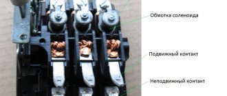
Switches, like all equipment, can be affected by both inductive and conducted noise.
Let's look at the different sources of interference at an industrial facility, and what kind of interference they create.
What problems can arise with the electrical network?
As many people know, the electricity generated by domestic networks and distributed to users' outlets is alternating current with a frequency of 50 hertz and a voltage of 220 volts. In principle, small deviations are allowed in the parameters, so the permissible operating range of 50-60 hertz and 220-230 volts most often appears on electrical appliances.
However, in reality, the current parameters in the outlet may differ significantly. At the same time, the greatest danger is not long-term deviations, but single episodes of short-term sharp increases in voltage, decreases in voltage, frequency changes, as well as moments of complete power outage for a fraction of a second.
What are the reasons for such failures? They are extremely diverse. There are poor performance of local electrical networks, dilapidated wiring of old houses, violations of the laying of power lines in new buildings, and the use of low-quality materials (wires, distribution equipment) during construction. In addition, sudden changes in voltage can be affected by the weather, neighbors turning on some powerful (in terms of energy consumption) device, plugging in a faulty device, and so on. Simply put, it is impossible to deal with possible failures in the power grid using any specific methods. We need universal solutions.
Methods of protection
Unfortunately, we cannot control the quality of the power grid, but it is quite possible to protect household appliances. Depending on what distortions a particular electrical device is sensitive to, the appropriate protection method is chosen. Various external devices, built-in electrical circuits, as well as shielding of structural elements and grounding help reduce noise levels.
An example of interference suppression is shown in Figure 3.
The following external devices are effective:
- Surge Protectors;
- IPB;
- frequency converters;
- adjustable transformers;
- network filters and filter cascades (the schematic diagram of a simple filter is shown in Figure 4).
Particularly difficult is the suppression of high-frequency impulse distortions in the range of several tens of MHz. Often, protection applied directly to the source of interference is used for these purposes.
The use of voltage stabilizers is justified in cases of regular voltage dips in the home network. If the current is consistently too low or too high, it is better to use a transformer.
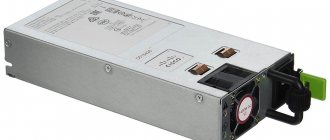
Uninterruptible power supplies have a high level of protection for computers and other sensitive electronics. Figure 5 shows a photo of an uninterruptible power supply to protect a computer.
These devices implement several protective functions, but the main one is supplying power to the devices for several minutes, followed by their correct shutdown. In order to achieve the maximum level of protection, it is logical to give preference to an uninterruptible power supply.
Methods of protection against voltage sags
It is difficult to imagine a modern enterprise, be it production, farming or service, without computers used for various purposes: accounting, automation, communications, etc. Complex computer equipment requires reliable and uninterrupted power supply, otherwise failures cannot be avoided.
Many consumers are interested in ways to compensate for voltage dips. The most theoretically effective is to improve network quality characteristics, but in practice this is practically impossible and costly.
In some cases, when the situation allows, they duplicate the supply line from remote areas, which can conditionally be considered electrically independent from each other.
A practically common solution is to purchase a device for protection against voltage dips or select the correct configuration when purchasing. Although this solution is the most profitable from a cost point of view, electrical and electronics manufacturers do not particularly help customers in this regard.
Purpose of a surge protector
It is known that you have an AC power supply of 220 Volts in your outlet. “Alternating voltage (current)” means that its magnitude and/or sign are not constant, but change over time according to a certain law.
The nature of generating electrical machines (generators) is such that a sinusoidal EMF is generated at the output terminals. However, everything would be fine if all devices were resistive in nature, there were no inrush currents, and did not contain pulse converters. Unfortunately, this does not happen, because... Most devices are inductive, capacitive in nature, brushed motors, and switching secondary power supplies. This whole convoluted set of words is the main culprit of electromagnetic interference.
We started the article by talking about electromagnetic interference for a reason. These interferences “spoil” the even shape of the sinusoid. So-called harmonics are formed. If we expand the real signal from the socket in the form of a Fourier series, we will see that the sine wave has been supplemented with various functions of different frequencies and amplitudes. The voltage waveform in a real outlet has become far from ideal.
So what's the end result? Poor power supply is a problem for radio transmitting devices. Simply, your TV or radio will experience interference. In addition to interference from consumers, the network contains interference of random origin that we cannot predict. These are surges, voltage drops due to power outages, switching on a powerful load, etc.
A surge protector is needed in order to:
- Filter out interference to cleanly power devices.
- Reduce interference from power supplies.
EMC series filters
Filters in this series (Figure 10) are compact and efficient two-stage RF power filters. They have a number of advantages: a high coefficient of attenuation of common-mode interference in the low-frequency region, a high coefficient of attenuation of anti-phase interference, and compact dimensions. The EMC series is focused on use in devices with switching power supplies.
Rice. 10. Appearance of EMC series filters
The main technical characteristics are given in Table 4.
Table 4. Basic electrical parameters of EMC series network filters
| Rated filter currents, A | Maximum leakage current, mA | Operating frequency range, MHz | Electrical insulation strength (within 1 minute), V | Rated voltage, V | Rated current, A | ||
| ~120 V 60 Hz for currents 3; 6; 10 A (15; 20 A) | ~250 V 50 Hz for currents 3; 6; 10 A (15; 20 A) | "conductor-body" | "conductor-conductor" | ||||
| 3; 6; 10 | 0,21 | 0,43 | 0,1…30 | 2250 | 1450 | ~250 | 3…30 |
| 15; 20; 30 | 0,73 | 1,52 | |||||
The electrical circuit of the EMC series filter is shown in Figure 11.
Rice. 11. Electrical diagram of two-stage filters of the EMC series
The attenuation of the interference signal in dB when the line is loaded onto a 50 Ohm matching resistor is shown in Figure 12.
Rice. 12. Attenuation of the interference signal with EMC series filters
Using network filters
The alternating voltage coming from the industrial network is characterized by a signal frequency of 50 Hz. When you plug in devices or start engines, signal harmonics with a frequency of less than 50 Hertz or higher than this value penetrate into the electrical network. Such harmonics affect the operation of pulsed equipment, forcing it to operate in extreme conditions. A power filter is used to cut off spurious frequencies. Passive radioelements are used as filter elements:
- capacitor;
- throttle;
- varistor;
- self-resetting fuse.
A capacitor is connected in parallel with the load. It does not allow direct current to pass through, while alternating current passes through it unhindered. The larger the capacitance of the capacitor, the less distortion of the sinusoidal signal will pass through it. This is characterized by the time of discharge and charge. Thus, as the frequency changes, the reactance of the capacitor also changes.
A varistor or nonlinear resistor is a semiconductor device with a nonlinear current-voltage characteristic. Depending on the level of the applied signal, its resistance changes. During normal operation, the varistor has a high resistance and does not affect the passing signal. If a voltage surge occurs, its resistance decreases, the input circuit is bypassed and the entire peak current passes through it. It is connected, like a capacitor, in parallel with the load.
Types of power filters
A power filter, smoothing out voltage surges and frequency distortions, is often used as an extension cord with the ability to connect several devices at the same time. You can find filters of different types and different price ranges on sale. The main requirements for them are to reduce the amount of various types of interference and maintain safety of use. They differ primarily in their characteristics:
- operating voltage;
- maximum power;
- methods of protection;
- operating voltage;
- additional features.
The maximum power value shows how much load the filter can simultaneously withstand. The filter radio elements used determine the method of protection. Additional features include backlit power buttons, the number of sockets, the presence of outputs for connecting telephone devices, USB outputs, while the filters are available with wires of different lengths. Power filters are produced in dielectric housings that are resistant to heat and shock.
Selecting a filter for protection
Using a low-quality surge protector not only does not improve the supply voltage parameters, but also leads to a short circuit or fire. Before purchasing, you will need to decide what kind of protection it should provide, whether it will be used as an extension cord, and the total peak power of the devices planned for connection. You should choose from well-known manufacturers whose products are certified and safe.
- Defender DFS 501. The best choice. The device has six sockets with a grounding contact with a power of 10A, two USB ports with a stabilized voltage of five volts. The sockets are made with protective shutters to protect connected devices from short circuits, overloads, and parasitic high-frequency signals. The length of the wire is two meters. In addition, the device is equipped with a status indicator.
- Pilot S 014. Economical solution with reliable contact in the socket. Includes basic protection elements and operation indication. Has six 10A outlets. Wire length 5 meters.
- Sven SV-0231018GR Pro. It is equipped with eight sockets with a grounding contact. The body is made of ABS plastic. In addition to standard inductive-capacitive protection, it has a varistor and an automatically reset fuse in the circuit. Wire length 1.8 meters.
- Daesung MC2345. Although it has only four sockets, each is equipped with a switch and is designed for a current of 16 amperes. Consists of high quality copper cable five meters long. Excellent performance against overload protection. Polycarbonate body, non-marking. The manufacturer gives a 5-year warranty, and does not carry out repairs, but replaces them with a new one.
- ERA USF-5es-1.5mB. The protective filter consists of 5 sockets. Protects wiring and equipment from damage due to power surges. The load current is 10A. All electrically conductive parts are made of copper. The length of the wire is one and a half meters.
How to deal with interference?
Interference caused by external currents can be eliminated in several ways:
- Use of CCTV cameras with insulation of the housing and connectors from the mounting bracket;
- Use only high-quality cables;
- Use of twisted pair cables with symmetrical conductor position;
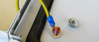
- Insulation of connectors and cable braid from the ground;
- It is inadmissible to lay the cable of the video surveillance system near the signal or power line;
- Installation of cameras with a grounded casing;
- Using galvanic isolation – transmitting a signal between devices without electrical contact between them;
- Application of optoelectronic isolation or video transformers;
- Application of broadband filters.
When the camera is mounted on a metal structure, and grounding is not possible, you can simply place a wooden spacer between the camera bracket and the mounting location to avoid direct contact of the camera with the metal surface. As a rule, in most cases the problem is solved in this way.
In some cases, interference may be due to poorly connected connectors, as well as their poor quality. In this regard, to prevent interference, experts recommend using a solder connection, since only in this case can a long period of cable operation be achieved at the connection points.
To combat interference in a video surveillance system with cameras located at a great distance from the base observation point, instead of coaxial cable, experts recommend using twisted pair cable with active amplifiers, which allows you to transmit the signal over long distances with minimal loss of image quality. In addition to the fact that twisted pair has a lower cost compared to coaxial, it can be used to build a large-scale video surveillance system with the ability to transmit signals without interference up to 4 km. At the same time, the structural features of this cable make it possible to protect the signal from interference and various interferences.
It is also recommended not to use cables from unknown manufacturers, choosing only proven ones. It is necessary to check its resistance and the amount of signal attenuation using an oscilloscope, as well as the uniformity of the shielding shell visually.
When installing video surveillance cameras over long distances, it is recommended to use a telephone TPPep cable, which has a fairly low attenuation coefficient and shows good results when used in video surveillance systems.
With this they read:
Video peephole for the front door: how to make the right choice?
Wireless video intercom: selection criteria and current models
Video intercom for a private home: selection criteria and connection
Outdoor CCTV cameras: key features, models and installation
Did you like the article? Share with friends on social networks!
- Paul
06/27/2017 at 03:31We have interference on the video through the common power supply. The cables are all twisted pair. What can you recommend?
Reply ↓
Alexander Starchenko
(Post author)07/26/2017 at 06:33
Change the power supply, it is better to ST BBP-50, so that there is no interference on the twisted pair, which is protected, 5A, it does not make noise
07/20/2018 at 12:25
how many cameras can be connected via twisted pair
Reply ↓
- Alexander Starchenko
(Post author)08/07/2018 at 05:45
What do you have in mind? You can connect one IP camera to one cable, 2 cameras respectively, etc.
09.19.2018 at 12:37
A month after installing the cameras, one began to behave strangely: the “color” of the image disappears and a multi-colored strip constantly moves across the screen, occasionally the image disappears completely. What could be the problem?
Reply ↓
- Alexander Starchenko
(Post author)11/20/2018 at 07:30
What cameras, what recorder, what is it connected to?
04.11.2018 at 22:08
Hello, there is a problem with the cameras, at night, during the day they take good pictures, at night there are glitches and breakdowns. Blocks, cables, grounding, they are all checked. Any tips?
Reply ↓
- Alexander Starchenko
(Post author)11/20/2018 at 07:35
Hello Albert! What do failures and disruptions mean? Are the cameras turning off? If yes, then there is obviously a power problem. At night the IR illumination turns on, it consumes a lot. How did you check? What is the voltage on the cameras with the light sensors sealed?
01/12/2020 at 17:50
Install a separate power supply for each camera and all interference will go away
Reply ↓
Why are voltage surges dangerous?
A voltage drop can be caused by the simultaneous shutdown of several powerful devices, a power failure, unstable operation of a substation due to overload, operation of a welding machine, poor quality of electrical wiring materials or its installation. Often a lightning strike along a power line results in a significant voltage surge.
Most differences are insignificant and go unnoticed by us, but not by technology. Any surge that causes the network voltage to rise above 250 Volts reduces the service life of connected devices or destabilizes their operation. Even insignificant deviations of 5-10%, which occur regularly, lead to failures in control units, reset of settings, and interference. Changes of 10-25% reduce the service life of devices by almost half. And voltage surges up to 300 Volts damage power supplies, control and touch panels, electric motors, and network equipment.
In most apartment buildings, the quality of electrical wiring leaves much to be desired; they cannot withstand the load, because dozens of devices operate simultaneously in each apartment. Of course, it is better to change the wiring in the apartment to minimize the likelihood of surges and prevent a fire. But even if this is not possible, you can protect yourself and your family.
Propagation of interference through the electrical network
Unfortunately, your question can be interpreted in different ways. If possible in more detail. Some interference that occurs in the depths of the network changes its character when tested by plugging a powerful load into an outlet (iron, electric fireplace, or whatever else comes to hand).
Added after 14 minutes Install an inductive filter on the ring on the radio network wires. But most likely the network has nothing to do with it, a 1000pF capacitor at the input of the audio path will help. To analyze the interference, connect the transmitter to an equivalent load. I wonder if the interference will go away?
Added after 18 minutes Setting the treble tone to zero also helps on TVs.
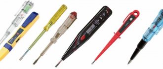
Measurement methods
Is it possible to see network distortions?
Using instruments, you can not only see the presence of interference, but also estimate its magnitude and determine the nature of its occurrence. There are special high-precision instruments for measuring various deviations in networks. The most common of them is a regular oscilloscope.
The device has a display (screen) on which an oscillogram of the measured current is displayed. By operating various oscilloscope modes, you can determine the nature and level of noise with high accuracy.
An example waveform is shown in Figure 6.
The oscillogram shows how the main signal is surrounded by parasitic currents that need to be cut off. By analyzing the nature of distortions, you can choose a way to suppress them. It is often enough to use a surge protector to get rid of typical interference that affects the operation of devices.
T series filters
Filters in this series (Figure 4) are high-performance radio frequency filters for power circuits of switching power supplies. The advantages of the series are excellent suppression of anti-phase and common-mode interference, compact dimensions. Low leakage currents allow the T series to be used in low power consumption applications.
Rice. 4. Appearance of the T series filter
The series includes two modifications - ET and VT, the technical characteristics of which are given in Table 2.
Table 2. Main technical characteristics of T series network filters
| Name | Maximum leakage current, mA | Operating frequency range, MHz | Electrical insulation strength (within 1 minute), V | Rated voltage, V | Rated current, A | ||
| ~120 V 60 Hz for currents 3; 6; 10 A (15; 20 A) | ~250 V 50 Hz for currents 3; 6; 10 A (15; 20 A) | "conductor-body" | "conductor-conductor" | ||||
| ET | 0,3 | 0,5 | 0,01…30 | 2250 | 1450 | ~250 | 3…20 |
| VT | 0,75 (1,2) | 1,2 (2,0) | |||||
The electrical circuit of the T series filter is shown in Figure 5.
Rice. 5. Electrical circuit of the T series filter
The attenuation of the interference signal in dB when the line is loaded onto a 50 Ohm matching resistor is shown in Figure 6.
Rice. 6. Attenuation of the interference signal with T series filters
Uninterruptible power supplies (UPS)
The UPS combines the functions of a surge protector and a stabilizer (except for the backup type), but in addition it allows the equipment to operate for some time after a power outage. Uninterruptible power supply systems come in three types: backup, interactive and double conversion.
The backup option is the simplest and cheapest solution. It passes current through the LC circuit, as in good surge protectors, and if the required voltage is not available, it switches to batteries. The disadvantages of backup uninterruptible power supply systems include a delay when switching to batteries (5 - 15 milliseconds).
Interactive UPSs are equipped with a step regulator that allows you to maintain the proper output voltage without using batteries, which increases their service life. Such uninterruptible power supplies are suitable for PCs and most household appliances.
Uninterruptible power supplies with double conversion convert the resulting alternating current into direct current, and at the output they again supply alternating current with the required voltage. The batteries are always connected to the network; switching is not performed. UPS of this type are more expensive, at the same time they create more noise during operation and heat up more. They are mainly used for equipment that requires power supply reliability: servers, medical equipment.
Where is the filter used and what to do if it is not there?
The fact is that in high-quality power supplies it must be installed directly on the board, and even more so on high-power power supplies, such as computer ones. But, unfortunately, your chargers for a smartphone, power supply from a laptop, electronic ballasts of fluorescent and LED lamps most often do not contain them. This is due to the fact that Chinese manufacturers are simplifying the circuits of their devices to reduce their cost. It often happens that there are places on the board for parts whose purpose is to filter interference, but they are simply not soldered and there are jumpers instead. Computer units are a separate issue; almost all of them have the same circuit, but the design is different, and the cheapest models do not have a filter.
You can reduce interference from your TV or other device that you want to protect and improve the properties of its power supply by adding such a filter to a regular power strip. You can assemble it yourself or extract it from a good, but unnecessary or faulty power supply unit.
Finally, we recommend watching a useful video on the topic:
A surge filter is a simple but useful device that will improve the quality of the power supply to your devices and reduce the harm caused to its frequency by the operation of switching power supplies, and the scope is quite wide - use it for any modern equipment. Its design allows even a novice radio amateur to repeat the circuit, and repairs are not difficult. The use of a surge protector is highly desirable for consumers of any kind.
It will be useful to read:
- Overvoltage in the network - what to do
- What are the types of interference in the electrical network?
- How to choose an uninterruptible power supply for your home
- What types of voltage stabilizers are there?
Published: 01/22/2018 Updated: 01/24/2019
Classification of interference in the electrical network
Interference occurring in the electrical network negatively affects the connected equipment. They can lead to serious malfunctions in a short period of time. Sudden voltage surges can be caused both by the influence of natural phenomena (lightning, magnetic fields), and by the quality of the line to the consumer or the equipment of the energy supply company.
Depending on the nature of the occurrence, interference can be of two types:
- high frequency (HF);
- pulsed.
High-frequency interference appears from electronic components of operating equipment connected to the network. For example, during the operation of a refrigerator, washing machine, and other equipment that has motors in its design. To a lesser extent from devices with switching power supplies: TV, tape recorder, computer, etc. RF interference is always present and it is impossible to completely remove it. Although this kind of interference exists, its negative impact is not great.
Pulse interference manifests itself in the form of noise, and can be either in the form of single pulses or their sequence. The parameters and shape of the pulses are usually chaotic; they arise due to sudden changes in current and voltage. These surges are caused by switching processes associated with the startup of powerful equipment or when a short circuit occurs, as well as magnetic fields.
There are several ways to deal with existing deviations in the operation of the electrical network. The most accessible way is to use voltage stabilizers or protective filters. The use of such devices in everyday life does not require alteration or modernization of the power line. The protected equipment is connected to them through a built-in socket, and they themselves are connected directly to a 220 V network through a plug.
How to protect home appliances from interference
Today, there are several effective ways to combat various physical abnormalities in the operation of the electrical network:
- Voltage regulator;
- uninterruptable power source;
- network filters.
A voltage stabilizer allows you to control the voltage level in the network and, if a sharp imbalance occurs, the device will stop supplying electricity to the consumer. The stabilizer itself is connected between the voltage source and the electricity consumer itself.
Stabilizer is an effective way to protect household appliances. The device stops supplying electricity to the consumer in the event of a power surge and resumes supply when the voltage returns to normal.
True, this method of dealing with interference is not always suitable as the main one. For example, when working with a computer, it is important for the user to ensure that all unsaved text data does not disappear. In this case, it is best to use a UPS - an uninterruptible power supply. The UPS includes a regular battery, which continues to keep the computer operational for some time after interference and subsequent power surges have occurred.
A cheaper way to make home appliances immune to interference is with surge protectors. They also do their job well and are used most often when connecting large household appliances: refrigerator, washing machine.
Measurement methods
Measuring noise in the network is carried out with special instruments. But if there are no such devices, then additional specific measures should be taken.
As a rule, the device that needs to measure interference in the electrical network will be powered from the same source that needs to be measured. If the wires are connected incorrectly, errors will occur when taking readings. The figure below shows the connection diagram of the device with which the measurement will be carried out:
An oscilloscope is also used to measure interference. If there is a storage tube, the device will be able to make a measurement. We talked about how to use an oscilloscope in a separate publication.
Now you know what causes interference in the electrical network and how to protect yourself from it. We hope the information provided was useful to you!
You probably don't know:
- Low voltage in the network - where to complain
- How to protect the cable from damage
- Errors when installing electrical wiring
Published: 02/03/2017 Updated: 11/07/2019
How and with what to measure interference
It is possible to measure interference in the electrical network and its direct impact using special instruments. The device is connected to a source where interference is observed. It is important to carry out the preparatory work correctly, which involves correctly connecting the device to the network. Otherwise, there will be an error in the readings, which will complicate the further course of action to combat interference.
All work can be done, for example, using an oscilloscope. The device is connected to the network and after some time the voltage and other characteristics are displayed on the display.
Interference classification
There are two types of interference in the electrical network: pulsed and high-frequency. The first ones occur when the device is turned on or off in the mains. They are dangerous because they can destroy all electronic equipment in the house in a short time. High-frequency interference always exists in the network, but is considered not as dangerous as pulsed interference.
Causes of the phenomenon:
- voltage fluctuations and deviations;
- impulse voltages;
- harmonics;
- frequency deviations;
- short voltage dips.
An electrical network in which interference is present may be subject to voltage deviations and fluctuations. You can learn more about what voltage surges are and how to protect yourself from them in our article.
The electrical network is also subject to pulse voltages. The reason may be natural phenomena in the form of a thunderstorm or switching operations that are carried out on the network.
An electrical network with multiple harmonics can be connected to a transformer through static frequency converters. The frequency and duration of harmonics will depend on the output frequency of the converter.
Frequency deviation occurs due to the fact that the power of the generators that produce electricity does not correspond to the consumed load. An electrical network that increases load power increases the frequency and speed of the generator.
If the electrical network receives an unexpected and sharp decrease in voltage, this means that a disturbance such as short voltage dips has occurred. The power grid restores normal operation after a certain time. This phenomenon occurs in power systems due to switching processes that are associated with the start and operation of high-power motors, and are also associated with short circuits.
Consumers must take into account the fact that it is impossible to eliminate or reduce the amount of interference generated by the operation of power systems to eliminate short circuits.
Main types of interference in the electrical network
There are a whole host of reasons that cause various types of interference. Any network can experience both pulsed and high-frequency interference. The first ones occur when turning the device on and off and are the most dangerous for household appliances. Physically, they represent a transient increase in voltage amplitude. A sharp voltage drop is fatal for many microcircuits that modern devices are equipped with.
As for high-frequency interference, it is worth noting that they are almost always observed in the network. It is not possible to completely get rid of them. You can observe RF interference during operation of a refrigerator, coffee maker and other appliances. They are transmitted not only by wire, but also over the air. However, they do not pose a big threat and have virtually no effect on the service life of home appliances.
What are the types of interference in the electrical network and how to remove them?
Technological progress in recent decades has introduced a large number of different devices and devices into the life of mankind. Today, many people cannot imagine their existence without a computer, TV, refrigerator and various household appliances.
All this technology is designed to help, and in some cases make a person’s life easier.
It is a long-known fact that the service life of any device is determined by the quality of the electrical network. An increase and decrease in voltage, various interferences and surges are unfavorable factors that contribute to the premature failure of any equipment. What are the main types of interference in the electrical network and how to protect yourself from unexpected expenses?
Network filters
The so-called surge protector is often just a splitter/extension cord, the protective functions of which are either virtually absent or minimal and can only protect against overload or short circuit.
However, hidden among the “decoys” are real network filters that, using an LC circuit, filter high-frequency interference in the network. The cost of such devices is naturally higher, but for some types of equipment, full filtration is necessary. Devices with an LC circuit have the “EM/RF Noise Reduction” feature
If you need this option, pay attention to it
High frequency interference
Surge filters ensure the safety of your equipment. They include a high-frequency interference filter that protects electrical appliances from various malfunctions. They also have a pulse noise filter (protection against pulse noise): thus, two problems are solved at once.
Classic network filters consist of a protection unit containing varistors, and their second component is a capacitive or inductive-capacitive filter. The capacitor together with the inductor is a high-frequency noise filter. And varistors create the most reliable impulse noise filter existing today.
Varistors (semiconductor resistance) play the role of “scissors” that “cut” high-frequency interference, voltage at the level of 800-1200 volts and thereby preserve the equipment connected to the filter sockets. Their purpose is protection against impulse noise. When the pulse is very powerful, the varistors may be destroyed, but the equipment will not be damaged. Pulse interference will not pose a threat to your electrical appliances if they are connected to the network through a surge protector.
A capacitive or LC filter, consisting of a capacitor (capacitive filter) or a capacitor and an inductor (LC filter), protects against high-frequency interference, reducing its harmful effects. The degree of reduction depends on the capacitance value of the capacitor and the inductance of the coil.
Mechanisms of penetration of pulsed interference
The inductive coupling mechanism is the main and most common physical process of the occurrence of pulsed noise.
Whenever an electric current passes through a conductive material, a magnetic field is created in the environment. If a second conductor is placed in this magnetic field, and the field itself is not stationary, then a current will be induced in the second conductor. This inductive coupling may be caused by a line inducing voltage on a nearby power or data line, or the lines may also interfere with each other. Lightning can cause a much stronger impact, since a lightning discharge produces electromagnetic fields on the ground that induce energy in the conductors of various electronic circuits in much the same way that a magnetic field from one conductor can induce impulse noise in an adjacent conductor with virtually no direct contact. with this line. This type of exposure in power lines causes various undesirable effects, such as:
- Destruction. This category includes all cases where high-energy transients cause immediate equipment failure. This is often visible physical damage, such as burnt or cracked circuit boards and components, and other obvious signs.
- Damage. They usually occur when pulsed noise enters equipment through inductive interaction. The electronic components then attempt to process the pulse noise as a valid logical command. As a result, the system becomes blocked, crashes occur, erroneous data is output, and files are lost or damaged.
- Scattering. These energy impacts are associated with repetitive stress on integrated circuit (IC) components. The materials used to make ICs can withstand a certain number of repeated energy bursts, but not for a significant period of time. The ongoing accumulation of thermal energy in the components and the resulting degradation of parameters will ultimately lead to failure of electronic equipment (EE). Therefore, to ensure reliable operation of the equipment, in accordance with the scope of its application, there are test standards necessary to ensure the resistance of the equipment to impulse noise.
- Pulse interference. Based on the IEC 50-161-90 standard, this is electromagnetic interference, which manifests itself in the path of a specific technical device (TS) as a sequence of individual pulses or transient processes. Microsecond impulse noise (MPI) is impulse noise with a total duration of 1 μs to 1 ms. In accordance with GOST R 51317.4.5-99 [1], the causes of microsecond interference are various switching processes occurring in high and low power power supply systems, as well as various electrical atmospheric phenomena. According to this standard, impulse noise can penetrate into power ports conductively (directly through the wires) through the following circuits: “wire-to-wire” (I), “wire-to-ground” (II) (Fig. 1).
MIPs that occur at the power supply ports of the device in a wire-to-wire (I) pattern are the most dangerous due to the higher energy value carried by the interference pulse (test pulse supplied in a wire-to-wire (I) pattern with an amplitude of 1 kV , which corresponds to degree of hardness 2, has an energy of 25 J, and the MIP supplied via the wire-to-ground circuit (II) is 5 J). Therefore, the pulsed noise energy entering the electronic device through the wire-to-ground circuit (II) is less important than the wire-to-wire circuit (I) due to the different impedance of these circuits.
Rice. 1. Paths of penetration of conducted interference
In these studies, the MIP parameters and the shape of the test pulse (Fig. 2), regulated by [1], were taken as the MIPs entering the electronic device.
Rice. 2. Typical shape of a microsecond interference test pulse: pulse rise time T1 = 1 μs; pulse duration T2 = 50 μs (at 50% of the amplitude); pulse repetition period - 1 minute; output resistance of the test generator - 10 Ohms (wire-to-ground circuit); output resistance of the test generator - 2 Ohms (wire-to-wire circuit)
Modern industry produces specialized devices called surge protection devices (SPDs), which are designed to protect electronic equipment from the unwanted effects of surge noise.
At the moment, there are a number of basic approaches to creating surge protection devices, namely: SPDs either absorb energy or discharge it into the protective grounding circuit, or a combination of approaches is used, thereby providing a higher level of EA resistance.
As a rule, the process of shunting a noise pulse to grounding is implemented using various types of nonlinear components, the main operating principle of which is to reduce the ohmic resistance when the applied voltage exceeds the response level (gas dischargers, varistors, TVS diodes, TVS thyristors).
The most common and cheapest element of protection against impulse noise of this type are metal oxide varistors (MOVs), which have a pronounced nonlinear current-voltage characteristic and are capable of reducing their own active resistance when the operating voltage is reached and, accordingly, shunting the protected object.
The MOV will remain in a high-resistance state, allowing energy to flow as usual, until a voltage greater than the MOV's trigger voltage is applied to the line. As a result, the current sharply increases (from a few milliamps to hundreds of amperes) flowing through the varistor, thereby protecting the electronic components of the device from overvoltage. In this case, the voltage supplied to the equipment will be maintained at an acceptable level until the interference ends.
MOVs are often combined with fusible links (FUs) that are placed along the power path of the protected equipment (Figure 3) to interrupt the circuit if the current level exceeds what the varistor can withstand. In this case, the heating will burn out the fuse-link, which is usually located next to or attached to the MOV. As a result, the electrical circuit will be open and further supply of energy to the protected equipment will become impossible.
Rice. 3. Typical varistor connection circuit
The traditional scheme of protection against impulse noise, based on the use of MOV, is the so-called “varistor triangle” circuit (Fig. 4), which is widely used in modern SPDs.
Rice. 4. SPD circuit based on a “varistor triangle”
However, such a scheme has a significant drawback, which poses a barrier to its comprehensive use as a protection device against high-voltage impulse noise, since this solution is “disposable”: after the fuse links have tripped, operator intervention is required to replace them. In addition, all semiconductor components have inertial properties. What matters is the “reaction” time, during which the protective element changes its electrical properties to timely protect the electronic device. In those cases when the duration of the interference pulse is short compared to the “reaction” time of the SPD, unhindered penetration of the interference pulse into the protected device occurs.
Additionally, varistors have a limit to the maximum amount of energy they can dissipate as heat. It should be noted that most manufacturers of protection devices indicate in the equipment documentation the value of the maximum absorbed interference energy. However, this parameter is not accurate, since it shows the total power of all varistors included in the SPD, and it can be considered an inadequate indicator of the degree of protection of the device. Since interference typically travels through a device's power supply ports in multiple directions, it is likely that at a local location in an electronic circuit, the transmitted energy will exceed the maximum energy dissipation value of the varistor located there.
In addition to varistors, there are other types of semiconductor limiters, which also have all of the above disadvantages inherent in semiconductor devices.
Table 1 compares existing types of limiters used in the field of protecting electronic devices. Table 1.
Comparison of surge protection elements
| Security element | Advantages | Flaws | Usage |
| Gas discharger | High permissible current value 2.5–150 kA. Low capacitance (no more than 2 pF). High insulation resistance (more than 1 GOhm). Low leakage current (less than 10 nA). | Relatively long response time associated with the duration of gas ionization. Dependence of gas ionization voltage on the rate of voltage rise at the terminals. | As the first stage of combined protection of power circuits from atmospheric and switching overvoltages. |
| Varistor | Short response time (10–20 ns). Wide range of operating currents and voltages (3–20 kV, 0.1 mA–90 kA). | Limited service life, directly dependent on the power and repetition rate of the overvoltage pulses. Dependence of the actuation voltage on the flowing current. | First and second stages of combined protection. Protection of power circuits and automotive electronics. Protection of electronic components of devices. |
| TVS diode | Low voltage limit levels (units of volts). Wide range of operating currents and voltages. High speed (at least 10-12 s). Small own capacity. | Low rated pulse current (up to 200 A). Relatively high cost. | For protecting components on a printed circuit board in the final stage of a combined protection system. |
| TVS thyristor | High performance (at least 10-9 s). Large control current (up to 90 mA). | Limited operating voltage range (up to 150 V). The protected device is shunted to ground after the pulse has passed. |
The conducted research revealed the possibility of creating a new principle of protection against impulse noise, the basis of which is the use of two-stage protection of converter equipment powered from an industrial network. In this case, a DC link is used as the input circuit.
In Fig. Figure 5 shows a simplified functional diagram of the proposed SPD. Such a device consists of a series-connected filter 1 (F1), a rectifier bridge, filter 2 (F2) and a protected load. Filter 1 is designed to ensure the passport operating mode of the rectifier bridge diodes, namely, to generate the required dI
/
dt
and
dU
/
dt
. Filter 2, consisting of inductor L3 and capacitors C4, C5 (with capacitor C4 being non-polar and C5 electrolytic), connected to the output of the power rectifier. This filter, in addition to providing the required voltage ripple coefficient (L3,C5), is an accumulator of “fast” pulse noise energy (L3C4).
Rice. 5. Schematic diagram of an SPD
In Fig. Figure 6 shows the equivalent circuit of the “fast” L3C4 filter, where r1
— internal resistance of the test generator simulating a microsecond voltage pulse;
Rn
is the load resistance. Such a circuit is a second-order link in which, when an external pulse is applied to the input, oscillatory processes can occur at the output. In accordance with the theory of automatic control, for such a circuit the transfer function must be analyzed for the absence of oscillatory processes.
Rice. 6. Circuit of a “fast” LC filter
The transfer function of the “fast” L3C4 filter has the form:
where ξ is the damping coefficient; T1 , T2 -
link time constants;
k
is the link transmission coefficient.
The link time constants and transfer function coefficients are calculated using the following formulas:
The criterion for analyzing the stability of a given link is that the damping coefficient must be greater than or equal to unity (ξ ≥ 1).
In Fig. Figure 7 shows a model of an SPD operating at a load of 600 W (when modeling the SPD its maximum power is assumed to be 600 W). In this model, the electrolytic capacitor C5, in addition to capacitance, also has its own resistance and inductance (the reactive parameters of the electrolytic capacitor are assumed to be averaged).
Rice. 7. SPD model in OrCAD package
Table 2 shows the parameters of the elements of the SPD equivalent circuit.
Table 2.
Parameters of SPD equivalent circuit elements
| Element designation | Purpose | Denomination |
| V1 | Sinusoidal voltage source | U = 220 V, f = 50 Hz |
| V2 | Microsecond pulse noise (MPI) generator | UA = 1 kV, T2 = 50 µs |
| D1, D2, D3, D4 | Bridge rectifier diodes | perfect |
| D5 | Auxiliary diode that prevents network energy from entering the microsecond noise generator | |
| D6 | R6D6 damping circuit diode | |
| R1 | A resistor simulating the internal resistance of a pulse noise source) regulating the type of test (“wire-to-wire” according to GOST R 51317.4.5-99) | 2 ohm |
| r3 | Internal resistance of throttle L3 | 0.1 ohm |
| r4 | Internal resistance of non-polar capacitor C4 | 0.01 Ohm |
| r5 | Internal resistance of electrolytic capacitor C5 | 0.02 Ohm |
| R6 | Resistor damping circuit R6D6 | 10 ohm |
| Rn | Active load resistance | 100 Ohm |
| L4 | Equivalent series inductance of non-polar capacitor C4 | 1 nH |
| L5 | Equivalent series inductance of electrolytic capacitor C5 | 100 µH |
| L3 | Inductance | 0.5 mH |
| C4 | Capacitance of a non-polar capacitor | 1.2 µF |
| C5 | Electrolytic capacitor capacity | 200 µF |
The parameters of the filter elements are selected in such a way that the voltage surge at the load does not exceed 500 V with a positive MIP amplitude of 1 kV (Fig. when exposed to an interference pulse at a time corresponding to the maximum instantaneous value of the supply sinusoidal voltage (in accordance with clause 8.2 of GOST [1]).
Rice. 8. Oscillograms of currents and voltages when exposed to a pulse with an amplitude of 1 kV with a phase shift of 90° relative to the sinusoidal voltage
The processes occurring in the “fast” L3C4 filter have the following sequence (Fig. 9): at the moment the pulse arrives, the inductor current begins to increase linearly, and the alternating component of the inductor current begins to flow through the capacitor (C4); at the moment of the end of the external influence (the end of the interference pulse), the current through the inductor, and therefore through the capacitor (C4), begins to decrease to its original value.
Rice. 9. Diagrams of currents and voltages in SPD elements under the influence of MIP
An electrolytic capacitor (C5) connected in parallel with a non-polar capacitor (C4) due to the presence of an equivalent series inductance ( lvn
) does not operate when exposed to pulsed noise.
After the end of the MIP, the energy accumulated in capacitor C4 is transferred to capacitor C5, which, with its time constant, is subsequently discharged into the load resistance.
Voltage relay
Voltage relays, also called breaker relays, open electrical circuits during voltage surges. After turning off the power, the relay checks the voltage status at short intervals and, if the values are normal, resumes the current supply.
Some models are equipped with regulators that allow you to configure the relay for different devices, setting the upper and lower limits of the differences for shutdown, as well as the time of subsequent activation. There are models of relay interrupters both for mounting in an electrical panel and for separate installation in an outlet.