Operating principle
To understand how electromagnets work, we need to look at their design.
A simple device explains the principle of operation of an electromagnet. When an electric charge flows through the body of the winding, magnetic field radiation occurs, penetrating the magnetic circuit. Magnetic flux formula
Inside a metal or ferromagnet, in accordance with the laws of physics, microscopic magnetic fields called domains are formed. Their fields, under the external influence of the winding, are arranged in a certain order. As a result, the magnetic forces of the domains are summed up, forming a strong magnetic field, giving the magnetic circuit the ability to attract massive metal objects.
Important! To stop electromagnetic induction, it is enough to disconnect the EM from the current source. In this case, a particle of the magnetic field will remain. This effect is called hysteresis.
Classification
Rotor - what is it?
EMs are distinguished by the methods of creating magnetic fields. There are three types of electromagnets:
- AC electromagnet;
- neutral DC device;
- polarized DC EM.
Magnets operating on alternating current change the direction of the magnetic flux along with twice the frequency of the electric current.
Neutral EMs connected to a direct current source create magnetic fluxes that do not depend on the direction of the electric current.
In polarized devices, the orientation of the magnetic flux is tied to the direction of the electric current. Polarized EMs consist of two magnets. One of them directs a polarizing magnetic field flux to the second electromagnet to turn it off.
Advantages of using electromagnets
The main advantage of an electric magnet over a constant source of magnetic field is that it is brought into working condition under the influence of electric current. That is, when it is necessary to exert a magnetic influence on a certain part of space, the current is turned on. This allows for rhythmic operation of the EM, which is successfully used in various types of electrical equipment, instruments and devices.
An electromagnet can be found in electric meters, separator units, transformers, television and audio equipment and other devices.
Powerful magnets are installed on overhead cranes in the workshops of metallurgical plants and winches of scrap metal collection enterprises.
Lifting electromagnets
One of the first applications of EMs is as speakers. The sound device is based on an electromagnet, which causes the membrane to vibrate in the audio range.
EMs are used in metal detectors to detect metal-containing objects underground, in water and in various areas.
Electromagnetic relay
“DEVICE AND PRINCIPLE OF OPERATION” “APPLICATION”
A relay is an electromechanical device designed for switching electrical circuits, signaling and control circuits. Most often, relays are used in control systems and are often both switching and amplifying elements of the circuit.
It should be remembered that, depending on the nature of the connection, network devices can be primary and secondary. Primary relays are connected directly to control control circuits, secondary relays are connected through instrument transformers, laboratory resistors, and shunt resistors.
Also, one of the advantages of relay devices and elements is the very high resistance between open contacts, which distinguishes them from solid-state relays that use semiconductor elements instead of a coil.
Solid-state devices are very sensitive to the quality of the control signal and have a high probability of false operation as a result of an abnormal electromagnetic pulse or when the voltage in the controlled network increases above optimal values.
In addition to standard electromagnetic relays, some sources include reed relays in this group of devices, the main distinguishing feature of which is the use of a magnetic field generated by a permanent or electromagnet as a control signal, instead of an electrical signal.
Design and principle of operation of an electromagnetic relay
Structurally, the electromagnetic relay is a coil that acts as a retractor. It consists of a base made of non-magnetic material on which a copper wire is wound, which, depending on the design, may be insulated with fabric or synthetic materials, but in most cases the conductor is coated with dielectric varnish.
When voltage is applied to the coil, a metal core connected to a pusher is retracted, which drives the contacts.
Depending on the purpose, the relay contact block may consist of normally open (open) or normally closed (closed) contacts; in some cases, the contact block may combine both types of contacts.
The relay structure can be understood in more detail if you break its components into blocks:
- control - serves to convert the control signal (in our case from electric to magnetic field);
- block of intermediate elements - activates the actuator;
- executive unit - acts directly on the controlled circuit. The contact group of the device can be considered as an executive unit.
Also, when designing control circuits using electromagnetic relays, it is necessary to take into account that since the sensitive element is an electromagnetic coil, the current in the winding does not increase or decrease instantly, but over a period of time.
In this regard, possible response delays must be taken into account. It is quite small, but in some situations it can affect the operation of other elements of the circuit.
Electromagnetic relays can be classified according to the following criteria:
Areas of use:
for control, protection or signaling circuits;
control power:
low power, control signal ≤1 W, medium power, control signal ranges from 1 to 9 W, high power - signal power ≥10 W;
response time to control signal:
inertia-free reaction time ≤ 0.001 sec., fast-acting - reaction time from 0.001 to 0.05 sec., slow reaction time from 0.05 to 1 sec., as well as time relay with adjustable response delay.
the nature of the control voltage:
DC - neutral, polarized and alternating current.
It is worthwhile to dwell on the features of DC relays. As mentioned above, they are divided into neutral and polarizing. The main difference between these two groups is that polarizing devices are sensitive to the polarity of the applied voltage, that is, the movable core changes its direction from right to left or vice versa depending on the polarity of the voltage.
DC electromagnetic relays are divided into:
- two-position;
- two-position with dominance;
- three-position or dead zone relays.
The operation of neutral type devices does not depend on the polarity of the supplied voltage. The disadvantages of relays using direct current as a control signal include the need to install power supplies to supply direct current and the high cost of the device itself.
AC relays do not have this, but they also have their drawbacks, such as the need to modify the design to eliminate vibration of the core. The operating parameters are worse than those of devices using a linear control signal, namely - worse sensitivity, much less electrical force. But at the same time, they can be directly connected to the AC electrical network.
To the begining
Application of electromagnetic relays
Perhaps, relays operating using the electromagnetic principle are most widely used in the field of distribution and production of electrical energy. Relay protection of high-voltage lines ensures trouble-free operation of substations and other connected equipment.
The control elements used in relay protection installations are designed for connection switching at operating voltages reaching several hundred thousand volts.
The widespread use of relay protection for high-voltage lines is due to:
- high durability of relay elements;
- quick response to changes in parameters of connected lines;
- ability to work in conditions of high intensity electromagnetic fields and insensitivity to the appearance of parasitic electrical potentials.
Also, through relay protection installations, power lines are backed up and damaged sections of the power network are immediately taken out of service, for example, when a line is shorted to ground or live parts are broken. To date, more reliable means of protecting power lines than relay protection have not yet been invented.
In addition, currently the electromagnetic type of relay is widely used in control systems for production and conveyor lines. Most often, this type of control systems is used in industries with high parasitic potentials making it impossible to use semiconductor control systems.
For example, there is a known case when, during the modernization of conveyor line control systems at one of the elevators, new equipment built with the latest semiconductor elements constantly failed.
As it later turned out, the cause of the breakdown was static electricity that occurs when grain moves along the conveyor belt, and since the potential equalization system was not provided in these premises, the question arose about moving the control panel to a protected room.
This was associated with enormous material costs. As a result, it was decided to switch to relay control units that are insensitive to static voltage.
Superconducting electromagnet
Superconductivity is considered the property of materials with resistance close to zero. Electromagnets with practically zero resistance have a super-powerful magnetic field. The force of magnetic influence can cause diamagnetic materials such as pieces of lead and organic objects to float in space.
As physicists have noticed, metals acquire the property of superconductivity at ultra-low temperatures. To obtain the superconductivity effect, the EM windings are placed in a Dewar flask with liquid helium, which is equipped with a valve to release the vapor of the substance. Superconducting magnets are used in medical equipment - MRI (magnetic resonance tomography) machines. Experimental hovercraft trains use superconducting magnets.
Superconducting magnet
Application of lifting and large-scale electromagnets
Electric motors and generators are vital in today's world. The motor takes electrical energy and uses a magnet to convert electrical energy into kinetic energy. A generator, on the other hand, converts motion using magnets to generate electricity. When moving large metal objects, lifting electromagnets are used. They are also necessary when sorting scrap metal, to separate cast iron and other ferrous metals from non-ferrous ones.
A real miracle of technology is the Japanese levitating train, capable of reaching speeds of up to 320 kilometers per hour. It uses electromagnets to help it float in the air and move incredibly fast.
The US Navy is conducting high-tech experiments with a futuristic electromagnetic rail gun. She can direct her projectiles over considerable distances with great speed. The projectiles have enormous kinetic energy, so they can hit targets without the use of explosives.
How to make a 12v electromagnet
The easiest way to make an electromagnet is to take a regular nail, wire and battery. An insulated wire is wound along the entire length of the rod. The ends of the conductor are pressed against the poles of the battery. To ensure that the charge is not wasted, one end of the wire is soldered to the positive contact. The other ending should be made in the form of a spring-loaded arc, which is pressed against the battery terminal with a minus sign. The bottom photo shows how you can make an electromagnet at home.
DIY electromagnet
Note! When making an electromagnet with a battery, you can use a contact block from an old device. To turn off the magnet, it will be enough to remove the battery from the contact box.
Reduced VxT loss
The winding for the electromagnet is made of copper or aluminum insulated wires. There are also superconducting electromagnets. Magnetic wire is made of soft magnetic material, most often steel (structural, cast and electrical), cast iron and iron alloys with cobalt or nickel. Reducing the eddy current loss (ECT) is carried out by creating a magnetic circuit from many sheets.
Calculations
Before you start assembling an electromagnet with your own hands, make a preliminary calculation of its parameters. Structural elements are calculated separately for DC and AC EVs.
For DC
Before making calculations, the required value of the magnetomotive force (MF) of the coil is determined. The winding parameters must provide the required MMF, at the same time the coil must not overheat, otherwise the insulating layer of the winding wire will be lost. The initial data for the calculation are the voltage in the wire of the electromagnetic coil and the required value of the magnetomotive force.
Methods for calculating DC electromagnets are constantly published on the Internet. There you can also select formulas for determining the MMF, the cross-section of the core and winding wire, and its length.
Additional Information. Mostly on the Internet they look for calculations of 12 volt electromagnets made by themselves. Depending on your needs, you can take different calculation paths. Basically, “recipes” are chosen to determine the cross-section and length of the winding wire powered by a standard “A” or “AA” format battery.
For AC
The basis for EM AC is the calculation of the winding. As in the previous case, they are guided by the initial requirements for the MMF value. Despite the large number of recommended calculation formulas, most often the “capabilities” of a device are determined by an experienced selection of the parameters of its design parts. Methods for calculating EM alternating current can always be found on the World Wide Web (Internet).
Main parts of DC electromagnets
Neutral DC electromagnets have the most favorable characteristics and are the most economical. Thanks to the large number of possible designs, these electromagnets can be easily adapted to different operating conditions and various device designs in which they are used. Therefore, they are most widespread.
With all the variety of such electromagnets encountered in practice, they have the following main parts of the same purpose (Fig. 2.1 - 2.3):
Ø coil with magnetizing winding 1 located on it;
Ø stationary part of the magnetic circuit made of ferromagnetic material 2;
Ø moving part of the magnetic circuit - armature 3.
The armature is separated from the remaining parts of the magnetic circuit by working and parasitic gaps and is a part of the electromagnet, which, perceiving the electromagnetic force, transmits it to the corresponding parts of the driven mechanism.
Depending on the location of the armature relative to the other parts of the electromagnet and the nature of the effect on the armature from the magnetic flux, DC electromagnets are divided into the following types:
¨ electromagnets with retractable armature;
¨ electromagnets with an external attracting armature;
¨ electromagnets with an external transversely moving armature.
One typical design of an electromagnet with a retractable armature is shown in Figure 10.1. A characteristic feature of such electromagnets
is that the anchor or,
Figure 10.1. Electromagnet with retractable armature.
as it can be called in this case, the movable core is located entirely or partially inside the coil with the winding. During the operation of the electromagnet, the armature, moving forward, is immersed in the coil. The retraction of the armature occurs both due to the magnetic flux passing through the end surface of the armature, and due to the action of magnetic fluxes emerging from its side surface. Figure 10.2 shows one of the types of electromagnets with an external
Figure 10.2. Electromagnet with external attracting armature. a - appearance of a relay with an electromagnet with an attractive armature;
b - cross-section of the electromagnet. pulling anchor.
These electromagnets have an armature located outside the coil. It is affected mainly by the working magnetic flux passing from the armature to the end of the core cap. As a result of this, the armature rotates within a small angle or makes a translational movement in the direction of the induction line of the working magnetic flux.
The design of an electromagnet with an external transversely moving armature is shown in Fig. 10.3.
Figure 10.3. An electromagnet with an external transversely moving armature.
The armature in such electromagnets is located outside the coil. The working magnetic flux acting on the armature passes from its side surface to the pole pieces, which have a special shape, in a certain way consistent with the shape of the side surface of the armature. As a result of the influence from the working magnetic flux, the armature moves across the magnetic lines, turning through a certain limited angle.
In each of the three listed groups of direct current electromagnets, in turn, there are a number of design varieties determined by the design of the magnetic circuit. In addition, depending on the method of switching on the electromagnet winding, the following are distinguished:
¨ electromagnets with parallel windings;
¨ electromagnets with series-connected windings.
In the first case, the winding is designed in such a way that it is switched on to fully charge the power source directly or through some additional resistance. The current in the parallel winding circuit is completely, or at least largely determined by its parameters. The series winding has virtually no effect on the current value of the circuit into which it is connected. The latter is determined by the parameters of the remaining elements of this circuit. Due to these features, some characteristics of parallel and series-connected electromagnets and, first of all, their dynamic characteristics are different.
b) Main parts of AC electromagnets.
The characteristics and design of such electromagnets are fundamentally different compared to DC electromagnets,
The magnetic flux created by the winding through which alternating current passes periodically changes in magnitude and direction (alternating magnetic flux), as a result of which the force of electromagnetic attraction pulsates from zero to maximum with double the frequency relative to the frequency of the supply current'.
However, for traction electromagnets, a decrease in the electromagnetic force below a certain level is unacceptable, since it leads to vibration of the armature, and in some cases, to a direct disruption of normal operation.
Therefore, in traction electromagnets operating with an alternating magnetic flux, it is necessary to resort to special measures to reduce the depth of the force pulsation.
The main way to reduce the pulsation of the total force acting on the armature of an electromagnet with a variable magnetic flux is the use of magnetic systems with split magnetic flux paths, along each of which alternating magnetic fluxes pass, shifted in phase relative to each other.
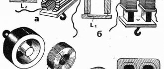
With all the variety of traction electromagnets encountered in practice, they consist of the following main parts of the same purpose (Fig. 10-4).
1 - coil with a magnetizing winding located on it (there may be several coils and several windings);
2 - stationary part of the magnetic circuit made of ferromagnetic material (base and core);
3 - moving part of the magnetic circuit (armature).
a B C)
Figure 10.4: a) sketch of an electromagnet with an external b) sketch of an electromagnet with an attracted armature. c) partially retractable anchor
The armature is separated from the remaining parts of the magnetic circuit by air gaps and is a part of the electromagnet, which, perceiving the electromagnetic force, transmits it to the corresponding parts of the driven mechanism.
The number and shape of the air gaps separating the moving part of the magnetic circuit from the stationary one depend on the design of the electromagnet. The air gaps in which useful force arises are called workers; air gaps in which there is no force in the direction of possible movement of the armature are parasitic.
The surfaces of the moving or stationary part of the magnetic circuit that limit the working air gap are called poles.
Depending on the location of the armature relative to the remaining parts of the electromagnet, electromagnets are distinguished
¨ with an external attracting anchor (Figure 10.5 a),
¨ electromagnets with a retractable armature (Figure 10.4 b)
¨ electromagnets with a transversely moving armature.
The latter system is practically not used in AC electromagnets. But in many cases, designs with an anchor are used, which has the features of both a retractable and an externally attracted one (Figure 10.4 c)
The forms of design of alternating current electromagnets are limited due to the need to make their magnetic cores laminated from thin sheets of electrical steel. The latter is dictated by the desire to minimize eddy current losses. For the same purpose, as well as to reduce losses due to hysteresis, it is necessary to use special technological methods in the manufacture of electromagnets, which in turn also affects their design.
Electromagnets are also distinguished according to a number of other characteristics:
v by the method of connecting the windings - with parallel and series windings;
v by the nature of the work - working in long-term, intermittent and short-term modes;
v by speed of action - fast-acting and slow-acting, etc.
Magnetic materials and their characteristics. Application in electromagnets.
For the manufacture of magnetic cores of electromagnets, soft magnetic materials are used. They are characterized by high permeability in weak and medium fields and low coercivity. They, as indeed all ferromagnetic materials, are characterized by the dependence of magnetization on temperature and the presence of a certain temperature (Curie point) within the solid state at which the material becomes non-magnetic.
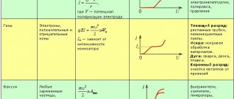
a) Characteristics of the magnetic state. For ferromagnetic materials, the relationship between magnetic induction and field strength is not unambiguous. It depends on the previous magnetic state and is determined by the points located inside the limiting magnetic hysteresis loop (Figure 10.5).
Figure 10.5 — Magnetic hysteresis loops
If the field strength in an initially demagnetized sample is increased, then the induction will increase along the initial magnetization curve (curve 1, Figure 10.5). When the field strength changes cyclically between equal positive and negative values of H
the induction will follow the so-called symmetrical or fundamental magnetic hysteresis loops, the configuration of which for a given material is determined by the limits of change in field strength.
A curve starting from the origin and connecting the vertices of the main loops, Figure 10.5. The magnetic hyseresis loop of a ferromagnetic material is called the main or switching magnetization curve (curve 2, Figure 10.5).
In electromagnets operating with alternating magnetic flux, continuous cyclic magnetization reversal occurs. Therefore, the magnetic state of their magnetic circuit is determined precisely by the commutation magnetization curve, and it is not indifferent how this curve is taken: by the commutation method using direct current or alternating current. When calculating certain magnets, you should use the data obtained for direct or alternating current magnets.
In cases where the field strength, having a constant component, varies within small limits, the change in induction occurs in a small private cycle - hysteresis. In this case, the relationship between induction and field strength can be approximately expressed through the average permeability in a particular cycle:
μΔ= where ΔΒ and ΔΗ are the increments of induction and tension that determine the particular cycle. Its value at each point of the normal curve is less than the permeability μ, and depends on the magnitude of the displacement field and the value of ΔΗ. The limit to which μΔ tends as ΔΗ decreases to zero is called the reversible permeability μΔ.
Also, materials for alternating current magnets also take into account
b) Magnetization reversal losses. When magnetization reversal (change in magnetic state) of a sample made of ferromagnetic material is expended, a certain amount of energy is released in the form of heat. The energy released during one magnetization reversal cycle is characterized by the area contained within the corresponding magnetic hysteresis loop.
c) Eddy current losses and general losses. With an alternating magnetic field in a ferromagnet, in addition to losses associated with hysteresis, losses also arise due to eddy currents. These currents appear under the influence of e. d.s., induced by an alternating magnetic flux in a ferromagnet. To reduce losses from eddy currents, the magnetic circuit must be made laminated, that is, made from a set of thin plates electrically isolated from each other. If the plates are thin, then we can assume that the magnetic flux is distributed evenly throughout their thickness, and the contours of the eddy currents have sides parallel to the sides of the cross section of the plate. Magnetic materials used in electromagnets .
In the manufacture of magnetic cores of direct and alternating current electromagnets, low-carbon electrical steels, silicon electrical steels, high-quality structural steels with a carbon content of up to 0.2 - 0.25%, cast steel, cast iron, special iron-nickel and iron-cobalt steels are used.
For magnetic cores of electromagnets of highly sensitive electromagnetic devices, iron-nickel alloys are used, which have a very low coercive force (0.01 - 0.1 a/cm) and extremely high permeability in weak fields (up to 300,000). The disadvantage of these alloys is their relatively low saturation induction (7000 - 10000 g
) and high sensitivity to mechanical influences.
The hardening that appears in this case leads to a strong deterioration in the magnetic properties. Low-carbon electrical steels (grades E, A, etc.), containing up to 0.04% carbon and produced in the form of sheets and rods, are most often used for the manufacture of low-power electromagnets. They have an insignificant coercive force (0.3 - 1.2 a/cm
) with high permeability (up to 6000) and saturation induction up to 21400
g
. Thanks to this, it is possible to allow significantly higher induction values than when using iron-nickel alloys, which is essential in electromagnets with high operating forces.
In the absence of strict requirements for Hc
and, for example, in power electromagnets, electromagnets of many switching devices and control relays, high-quality structural steels (grades 0; 1; 2 and thin sheets 0.5; 0.8; 10; 15 and 20) are used for the manufacture of magnetic cores, having appropriate heat treatment, a coercivity from
0.7
to 3.5
a/cm
and a maximum permeability of 2000–4000.
In some cases, especially for large electromagnets, for technological reasons, parts of the magnetic cores are made of cast steel and cast iron, which have relatively low magnetic properties. In normal production, steel and cast iron castings are not subjected to additional heat treatment, but annealing can significantly improve their magnetic properties. Silicon steels (grades E11, E21, etc.) are used for the manufacture of magnetic cores of high-speed DC electromagnets. Possessing high magnetic properties (Hc = 0.2 - O.7 a/cm
=5000 - 10000 and ВS = 19200 - 21000
g
) they have several times lower electrical conductivity, which leads to a decrease in eddy currents and, therefore, reduces their influence on the speed of operation of the electromagnet. They are also widely used in AC electromagnets.
From the point of view of reducing the size and weight of electromagnets, which is especially important for many cases of their special application, alloys of iron with cobalt (permendur type) are of great interest due to their high saturation induction (ВS = 23600 gs)
with a fairly low coercive force (1.2 - 1.6
a/cm
) and high permeability (up to 4500).
For the manufacture of magnetic cores of electromagnets operating with alternating magnetic flux, silicon electrical steels are used almost exclusively. They are characterized by low hysteresis losses due to the insignificant coercive force and low eddy current losses due to increased electrical resistivity. To reduce losses due to eddy currents, magnetic cores are manufactured in the form of thin sheets with a thickness of 0.1 to 1 m.
The chemical composition and properties of these steels are standardized by GOST 802-54, which includes 28 grades. The main difference between them, which determines their properties, is the silicon content and the nature of mechanical processing (rolling) during the sheet production process.
An increase in silicon content leads to an increase in magnetic permeability in weak and medium fields, a decrease in losses and coercive force. However, this increases the hardness and brittleness of the material, which makes it difficult to manufacture parts from it.
Iron-nickel steels, which have very high initial and maximum permeability, low losses and low coercive force values, are used for electromagnets only in exceptional cases when particularly high sensitivity is required. In general, due to the low saturation induction, their use in electromagnets is, as a rule, impractical.
Neutral DC electromagnets have the most favorable characteristics and are the most economical. Thanks to the large number of possible designs, these electromagnets can be easily adapted to different operating conditions and various device designs in which they are used. Therefore, they are most widespread.
With all the variety of such electromagnets encountered in practice, they have the following main parts of the same purpose (Fig. 2.1 - 2.3):
Ø coil with magnetizing winding 1 located on it;
Ø stationary part of the magnetic circuit made of ferromagnetic material 2;
Ø moving part of the magnetic circuit - armature 3.
The armature is separated from the remaining parts of the magnetic circuit by working and parasitic gaps and is a part of the electromagnet, which, perceiving the electromagnetic force, transmits it to the corresponding parts of the driven mechanism.
Depending on the location of the armature relative to the other parts of the electromagnet and the nature of the effect on the armature from the magnetic flux, DC electromagnets are divided into the following types:
¨ electromagnets with retractable armature;
¨ electromagnets with an external attracting armature;
¨ electromagnets with an external transversely moving armature.
One typical design of an electromagnet with a retractable armature is shown in Figure 10.1. A characteristic feature of such electromagnets
is that the anchor or,
Figure 10.1. Electromagnet with retractable armature.
as it can be called in this case, the movable core is located entirely or partially inside the coil with the winding. During the operation of the electromagnet, the armature, moving forward, is immersed in the coil. The retraction of the armature occurs both due to the magnetic flux passing through the end surface of the armature, and due to the action of magnetic fluxes emerging from its side surface. Figure 10.2 shows one of the types of electromagnets with an external
Figure 10.2. Electromagnet with external attracting armature. a - appearance of a relay with an electromagnet with an attractive armature;
b - cross-section of the electromagnet. pulling anchor.
These electromagnets have an armature located outside the coil. It is affected mainly by the working magnetic flux passing from the armature to the end of the core cap. As a result of this, the armature rotates within a small angle or makes a translational movement in the direction of the induction line of the working magnetic flux.
The design of an electromagnet with an external transversely moving armature is shown in Fig. 10.3.
Figure 10.3. An electromagnet with an external transversely moving armature.
The armature in such electromagnets is located outside the coil. The working magnetic flux acting on the armature passes from its side surface to the pole pieces, which have a special shape, in a certain way consistent with the shape of the side surface of the armature. As a result of the influence from the working magnetic flux, the armature moves across the magnetic lines, turning through a certain limited angle.
In each of the three listed groups of direct current electromagnets, in turn, there are a number of design varieties determined by the design of the magnetic circuit. In addition, depending on the method of switching on the electromagnet winding, the following are distinguished:
¨ electromagnets with parallel windings;
¨ electromagnets with series-connected windings.
In the first case, the winding is designed in such a way that it is switched on to fully charge the power source directly or through some additional resistance. The current in the parallel winding circuit is completely, or at least largely determined by its parameters. The series winding has virtually no effect on the current value of the circuit into which it is connected. The latter is determined by the parameters of the remaining elements of this circuit. Due to these features, some characteristics of parallel and series-connected electromagnets and, first of all, their dynamic characteristics are different.
b) Main parts of AC electromagnets.
The characteristics and design of such electromagnets are fundamentally different compared to DC electromagnets,
The magnetic flux created by the winding through which alternating current passes periodically changes in magnitude and direction (alternating magnetic flux), as a result of which the force of electromagnetic attraction pulsates from zero to maximum with double the frequency relative to the frequency of the supply current'.
However, for traction electromagnets, a decrease in the electromagnetic force below a certain level is unacceptable, since it leads to vibration of the armature, and in some cases, to a direct disruption of normal operation.
Therefore, in traction electromagnets operating with an alternating magnetic flux, it is necessary to resort to special measures to reduce the depth of the force pulsation.
The main way to reduce the pulsation of the total force acting on the armature of an electromagnet with a variable magnetic flux is the use of magnetic systems with split magnetic flux paths, along each of which alternating magnetic fluxes pass, shifted in phase relative to each other.
With all the variety of traction electromagnets encountered in practice, they consist of the following main parts of the same purpose (Fig. 10-4).
1 - coil with a magnetizing winding located on it (there may be several coils and several windings);
2 - stationary part of the magnetic circuit made of ferromagnetic material (base and core);
3 - moving part of the magnetic circuit (armature).
a B C)
Figure 10.4: a) sketch of an electromagnet with an external b) sketch of an electromagnet with an attracted armature. c) partially retractable anchor
The armature is separated from the remaining parts of the magnetic circuit by air gaps and is a part of the electromagnet, which, perceiving the electromagnetic force, transmits it to the corresponding parts of the driven mechanism.
The number and shape of the air gaps separating the moving part of the magnetic circuit from the stationary one depend on the design of the electromagnet. The air gaps in which useful force arises are called workers; air gaps in which there is no force in the direction of possible movement of the armature are parasitic.
The surfaces of the moving or stationary part of the magnetic circuit that limit the working air gap are called poles.
Depending on the location of the armature relative to the remaining parts of the electromagnet, electromagnets are distinguished
¨ with an external attracting anchor (Figure 10.5 a),
¨ electromagnets with a retractable armature (Figure 10.4 b)
¨ electromagnets with a transversely moving armature.
The latter system is practically not used in AC electromagnets. But in many cases, designs with an anchor are used, which has the features of both a retractable and an externally attracted one (Figure 10.4 c)
The forms of design of alternating current electromagnets are limited due to the need to make their magnetic cores laminated from thin sheets of electrical steel. The latter is dictated by the desire to minimize eddy current losses. For the same purpose, as well as to reduce losses due to hysteresis, it is necessary to use special technological methods in the manufacture of electromagnets, which in turn also affects their design.
Electromagnets are also distinguished according to a number of other characteristics:
v by the method of connecting the windings - with parallel and series windings;
v by the nature of the work - working in long-term, intermittent and short-term modes;
v by speed of action - fast-acting and slow-acting, etc.
Magnetic materials and their characteristics. Application in electromagnets.
For the manufacture of magnetic cores of electromagnets, soft magnetic materials are used. They are characterized by high permeability in weak and medium fields and low coercivity. They, as indeed all ferromagnetic materials, are characterized by the dependence of magnetization on temperature and the presence of a certain temperature (Curie point) within the solid state at which the material becomes non-magnetic.
a) Characteristics of the magnetic state. For ferromagnetic materials, the relationship between magnetic induction and field strength is not unambiguous. It depends on the previous magnetic state and is determined by the points located inside the limiting magnetic hysteresis loop (Figure 10.5).
Figure 10.5 — Magnetic hysteresis loops
If the field strength in an initially demagnetized sample is increased, then the induction will increase along the initial magnetization curve (curve 1, Figure 10.5). When the field strength changes cyclically between equal positive and negative values of H
the induction will follow the so-called symmetrical or fundamental magnetic hysteresis loops, the configuration of which for a given material is determined by the limits of change in field strength.
A curve starting from the origin and connecting the vertices of the main loops, Figure 10.5. The magnetic hyseresis loop of a ferromagnetic material is called the main or switching magnetization curve (curve 2, Figure 10.5).
In electromagnets operating with alternating magnetic flux, continuous cyclic magnetization reversal occurs. Therefore, the magnetic state of their magnetic circuit is determined precisely by the commutation magnetization curve, and it is not indifferent how this curve is taken: by the commutation method using direct current or alternating current. When calculating certain magnets, you should use the data obtained for direct or alternating current magnets.
In cases where the field strength, having a constant component, varies within small limits, the change in induction occurs in a small private cycle - hysteresis. In this case, the relationship between induction and field strength can be approximately expressed through the average permeability in a particular cycle:
μΔ= where ΔΒ and ΔΗ are the increments of induction and tension that determine the particular cycle. Its value at each point of the normal curve is less than the permeability μ, and depends on the magnitude of the displacement field and the value of ΔΗ. The limit to which μΔ tends as ΔΗ decreases to zero is called the reversible permeability μΔ.
Also, materials for alternating current magnets also take into account
b) Magnetization reversal losses. When magnetization reversal (change in magnetic state) of a sample made of ferromagnetic material is expended, a certain amount of energy is released in the form of heat. The energy released during one magnetization reversal cycle is characterized by the area contained within the corresponding magnetic hysteresis loop.
c) Eddy current losses and general losses. With an alternating magnetic field in a ferromagnet, in addition to losses associated with hysteresis, losses also arise due to eddy currents. These currents appear under the influence of e. d.s., induced by an alternating magnetic flux in a ferromagnet. To reduce losses from eddy currents, the magnetic circuit must be made laminated, that is, made from a set of thin plates electrically isolated from each other. If the plates are thin, then we can assume that the magnetic flux is distributed evenly throughout their thickness, and the contours of the eddy currents have sides parallel to the sides of the cross section of the plate. Magnetic materials used in electromagnets .
In the manufacture of magnetic cores of direct and alternating current electromagnets, low-carbon electrical steels, silicon electrical steels, high-quality structural steels with a carbon content of up to 0.2 - 0.25%, cast steel, cast iron, special iron-nickel and iron-cobalt steels are used.
For magnetic cores of electromagnets of highly sensitive electromagnetic devices, iron-nickel alloys are used, which have a very low coercive force (0.01 - 0.1 a/cm) and extremely high permeability in weak fields (up to 300,000). The disadvantage of these alloys is their relatively low saturation induction (7000 - 10000 g
) and high sensitivity to mechanical influences.
The hardening that appears in this case leads to a strong deterioration in the magnetic properties. Low-carbon electrical steels (grades E, A, etc.), containing up to 0.04% carbon and produced in the form of sheets and rods, are most often used for the manufacture of low-power electromagnets. They have an insignificant coercive force (0.3 - 1.2 a/cm
) with high permeability (up to 6000) and saturation induction up to 21400
g
. Thanks to this, it is possible to allow significantly higher induction values than when using iron-nickel alloys, which is essential in electromagnets with high operating forces.
In the absence of strict requirements for Hc
and, for example, in power electromagnets, electromagnets of many switching devices and control relays, high-quality structural steels (grades 0; 1; 2 and thin sheets 0.5; 0.8; 10; 15 and 20) are used for the manufacture of magnetic cores, having appropriate heat treatment, a coercivity from
0.7
to 3.5
a/cm
and a maximum permeability of 2000–4000.
In some cases, especially for large electromagnets, for technological reasons, parts of the magnetic cores are made of cast steel and cast iron, which have relatively low magnetic properties. In normal production, steel and cast iron castings are not subjected to additional heat treatment, but annealing can significantly improve their magnetic properties. Silicon steels (grades E11, E21, etc.) are used for the manufacture of magnetic cores of high-speed DC electromagnets. Possessing high magnetic properties (Hc = 0.2 - O.7 a/cm
=5000 - 10000 and ВS = 19200 - 21000
g
) they have several times lower electrical conductivity, which leads to a decrease in eddy currents and, therefore, reduces their influence on the speed of operation of the electromagnet. They are also widely used in AC electromagnets.
From the point of view of reducing the size and weight of electromagnets, which is especially important for many cases of their special application, alloys of iron with cobalt (permendur type) are of great interest due to their high saturation induction (ВS = 23600 gs)
with a fairly low coercive force (1.2 - 1.6
a/cm
) and high permeability (up to 4500).
For the manufacture of magnetic cores of electromagnets operating with alternating magnetic flux, silicon electrical steels are used almost exclusively. They are characterized by low hysteresis losses due to the insignificant coercive force and low eddy current losses due to increased electrical resistivity. To reduce losses due to eddy currents, magnetic cores are manufactured in the form of thin sheets with a thickness of 0.1 to 1 m.
The chemical composition and properties of these steels are standardized by GOST 802-54, which includes 28 grades. The main difference between them, which determines their properties, is the silicon content and the nature of mechanical processing (rolling) during the sheet production process.
An increase in silicon content leads to an increase in magnetic permeability in weak and medium fields, a decrease in losses and coercive force. However, this increases the hardness and brittleness of the material, which makes it difficult to manufacture parts from it.
Iron-nickel steels, which have very high initial and maximum permeability, low losses and low coercive force values, are used for electromagnets only in exceptional cases when particularly high sensitivity is required. In general, due to the low saturation induction, their use in electromagnets is, as a rule, impractical.
Examples of using EM
The following devices can be cited as examples of the use of electromagnets:
- TVs;
- transformers;
- car starting devices.
TVs
Modern homes are usually filled with various electrical appliances. Being near a television receiver, they can influence the television screen (TV) by magnetic induction. TV already has built-in protection against screen magnetization. If multi-colored spots appear on the display field, then turn off the device for 10-20 minutes. Built-in protection will remove magnetization of the screen.
In some cases, this method does not provide the desired help. Then a special electromagnet is used, which is called a choke. This is a kind of induction coil. The device is connected to a household power outlet and passed along and across the screen. As a result, the induced magnetic fields are absorbed by the inductor.
Transformers
The design of transformers is very similar to the structure of electromagnets. Both there and there there are windings and cores. The difference between a transformer and an EM is that the former has a closed magnetic circuit. Therefore, the summed magnetic force is nullified by counter magnetic fluxes.
Car starting device
The car starter works as a starting device for the engine. It turns on while the engine is starting. The temporary transfer of starting force to the engine crankshaft is provided by a retractor electromagnet.
When you turn the key in the ignition switch, the EM pulls the gear into the crankshaft teeth. During contact, the starter motor cranks the engine until a fuel combustion cycle occurs in the engine cylinders. The traction relay then turns off the electromagnet and the starter gear returns to its original position. After which the car can move.
Starter with traction relay
Electromagnets have entered the sphere of human activity so tightly that existence without them is unthinkable. Simple devices can be found everywhere. Knowledge of the principle of their operation will allow the home handyman to cope with minor repairs of household electrical devices.