Electric motor winding terminals - connection diagrams
Designation of stator winding terminals
Each stator of a three-phase electric motor has three coil groups (windings) - one for each phase, and each coil group has 2 terminals - the beginning and end of the winding, i.e. There are only 6 pins that are signed as follows:
- C1 (U1) is the beginning of the first winding, C4 (U2) is the end of the first winding.
- C2 (V1) is the beginning of the second winding, C5 (V2) is the end of the second winding.
- C3 (W1) is the beginning of the third winding, C6 (W2) is the end of the third winding.
Conventionally, in the diagrams, each winding is depicted as follows:
The beginnings and ends of the windings are brought out into the terminal box of the electric motor in the following order:
Depending on the connection of these terminals, such parameters of the electric motor as the supply voltage and the rated stator current change. which circuit to use to connect the electric motor windings from the passport data.
The main winding connection diagrams are triangle (denoted by Δ) and star (denoted by Y), which we will analyze in this article.
Note: In the terminal box of some electric motors you can only see three terminals - this means that the motor windings are already connected inside its stator. As a rule, the windings inside the stator are connected when repairing an electric motor (if the factory windings are burned out). In such motors, the windings are usually connected in a star configuration and are designed for connection to a 380 Volt network. To connect such a motor, you simply need to supply three phases to its three outputs.
Connection diagram of electric motor windings according to the “triangle” diagram
To connect the windings of an electric motor according to the “triangle” diagram, it is necessary: connect the end of the first winding (C4/U2) to the beginning of the second (C2/V1), the end of the second (C5/V2) to the beginning of the third (C3/W1), and the end of the third windings (C6/W2) - with the beginning of the first (C1/U1).
Conventionally, this is depicted in the diagram as follows:
Voltage is applied to terminals “A”, “B” and “C”.
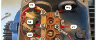
In the terminal box of the electric motor, the connection of the windings according to the “triangle” diagram has the following form:
A, B, C—connection points for the power cable.
Connection diagram of electric motor windings according to the “star” scheme
To connect the windings of an electric motor in a star configuration, it is necessary to connect the ends of the windings (C4/U2, C5/V2 and C6/W2) to a common point, while voltage is applied to the beginnings of the windings (C1/U1, C2/V1 and C3/W1 ).
Conventionally, this is depicted in the diagram as follows:
In the terminal box of the electric motor, the star connection of the windings has the following form:
Definition of winding terminals
Sometimes situations arise when, after removing the cover from the terminal box of an electric motor, you are horrified to discover the following picture:
In this case, the winding terminals are not labeled, what should I do? Don't panic, this issue can be completely resolved.
The first thing to do is to divide the leads into pairs, each pair should have leads related to one winding, this is very easy to do, we will need a tester or a two-pole voltage indicator.
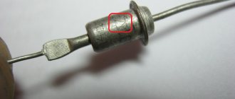
If using a tester, set its switch to the resistance measurement position (underlined by a red line); when using a bipolar voltage indicator, before use, it is necessary to touch the live parts under voltage for 5-10 seconds to charge it and check its functionality.
Next, you need to take any one terminal of the winding, conditionally take it as the beginning of the first winding and accordingly sign it “U1”, then touch the “U1” terminal we signed with one tester or voltage indicator probe, and touch with the second probe any other terminal from the remaining five unsigned ends. If, having touched the second terminal with the second probe, the tester readings have not changed (the tester shows one) or in the case of the voltage indicator - not a single light comes on - we leave this end and touch the other terminal of the remaining four ends with the second probe, and touch the ends with the second probe to until the tester readings change, or, in the case of a voltage indicator, until the “Test” light comes on. Having found the second terminal of our winding in this way, we accept it conditionally as the end of the first winding and sign it “U2” accordingly.
We proceed in the same way with the remaining four pins, also dividing them into pairs and signing them respectively as V1, V2 and W1, W2. You can see how this is done in the video below.
Now that all the pins are divided into pairs, it is necessary to determine the actual beginnings and ends of the windings. This can be done in two ways:
The first and simplest method is the selection method, which can be used for electric motors with a power of up to 5 kW. To do this, we take our conditional ends of the windings (U2, V2 and W2) and connect them, and briefly, preferably no more than 30 seconds, apply three-phase voltage to the conditional beginnings (U1, V1 and W1):
If the engine starts and runs normally, then the beginnings and ends of the windings are determined correctly; if the engine hums a lot and does not develop the proper speed, then there is an error somewhere. In this case, you just need to swap any two terminals of one winding, for example U1 with U2, and start again:
Designation of winding terminals of asynchronous machines
GENERAL ISSUES
TESTING OF ASYNCHRONOUS MACHINES
1.1. Nominal values and basic definitions
According to their design, asynchronous machines are of three-phase and single-phase current, with phase and squirrel-cage rotors, for general industrial and special purposes. Asynchronous machines can operate in motor, generator and electromagnetic brake modes; can be excited from both the stator and rotor sides.
The rated data of an electrical machine are the data indicated on the nameplate and characterizing its rated operating mode: rated power, rated voltage, rated current, rated speed, rated efficiency and power factor. The term “nominal” can also be applied to data not indicated on the nameplate of an electrical machine, but relating to its rated operating mode, for example: rated torque, rated slip. The nominal data of the machine refers to its operation at altitudes above sea level of up to 1000 m and at ambient temperatures up to +40°C.
The nominal operating mode of an electric machine is the mode for which the machine is intended by the manufacturer and in which it must operate throughout its entire service life. According to GOST 183-74 “Rotating electric machines. General technical conditions" consider the following nominal modes of an electric machine: continuous (S1); short-term (S2) and intermittently (S3).
The short-term nominal operating mode of an electric machine is characterized by a working period of 10, 30, 60, 90 minutes, respectively.
The intermittent-short-term operating mode is characterized by a relative ON duration (DS), i.e. the ratio of the duration of the working period to the duration of the cycle (the total duration of the working period and pause). According to the standard, the PV is 15, 25, 40, 60% with a duration of one cycle of no more than 10 minutes, unless otherwise specified in the technical specifications or factory requirements.
The load of an electric machine is the power that the electric machine develops at a given time. The load is expressed in watts or kilowatts, and also as a percentage or fraction of the rated power. The load can be specified by the current consumed or supplied by the electrical machine at a given time, and is expressed in amperes, as a percentage or as a fraction of the rated current. The engine load is determined by the amount of braking torque on the output shaft. To change the engine load, you must change the braking torque on its shaft.
The direction of rotation of an electric motor with a horizontal shaft is determined from the side where it is connected to the working mechanism: clockwise - right rotation, counterclockwise - left rotation.
Designation of winding terminals of asynchronous machines
In electrical machines, winding terminals must be designated in accordance with GOST 183-74 for machines developed before 1987 or being modernized, and in accordance with GOST 26772-85 “Rotating electric machines. Designation of terminals and direction of rotation" for machines manufactured from 01/01/87.
According to GOST 183-74, the terminals of asynchronous machines are designated as follows: stator windings - the letter “C”; rotor windings - letter “P”. Three-phase windings, in addition to letters, are designated by numbers: the beginnings of the phases – by the numbers “1, 2, 3”, the ends of the phases – by the numbers “4, 5, 6”; the zero point (regardless of whether it is grounded or not) is numbered “0”.
If a three-phase machine does not have sectioned and composite windings on the stator, then the designations of the winding terminals on the stator must be made in accordance with Table. 1.1. The designations of the stator winding terminals of single-phase machines are made according to the data given in table. 1.2.
According to the standard, the contact rings of the rotors of three-phase asynchronous motors are designated by letters corresponding to the designations of the rotor winding terminals connected to them (Table 1.3). In this case, the rings are arranged in phase order, and ring P1, corresponding to the first phase, should be the furthest from the rotor winding. With three outputs, the winding zero point is not output.
The corresponding tables show designations in accordance with GOST 26772-85.
Table 1.1. Names of stator winding terminals of asynchronous machines and their designations
| Winding connection diagram | Number of pins | Name of phase and output | Pin designations | ||
| GOST 183-74 | GOST 26772-85 | ||||
| Start | end | Start | end | ||
| Open circuit | First phase | C1 | C4 | U1 | U2 |
| Second phase | C2 | C5 | V1 | V2 | |
| Third phase | C3 | C6 | W1 | W2 | |
| Star connection | or | First phase | C1 | U | |
| Second phase | C2 | V | |||
| Third phase | C3 | W | |||
| Zero phase (star point) | N | ||||
| Triangle connection | First conclusion | C1 | U | ||
| Second conclusion | C2 | V | |||
| Third conclusion | C3 | W |
Table 1.2. Designation of terminals of single-phase machines
| Number of pins | Name of stator winding terminals | Pin designation | ||
| GOST 183-74 | GOST 26772-85 | |||
| Start | end | Start | end | |
| Main winding | C1 | C2 | U1 | U2 |
| Auxiliary winding | IN 1 | AT 2 | Z1 | Z2 |
Table 1.3. Designation of rotor winding terminals
| Number of pins | Name of phase and output | Pin designation | |
| GOST 183-74 | GOST 26772-85 | ||
| 3 or 4 | First phase | P1 | K |
| Second phase | P2 | L | |
| Third phase | P3 | M | |
| Zero phase (star point) | Q |
Test methods for asynchronous machines
When testing asynchronous motors, the tests of no-load, short circuit and direct load close to the rated load are of greatest importance [1]. To effectively use the experimental results, it is also necessary to know the value of the active phase resistance of the stator winding of the machine.
All methods used in industrial testing of electrical machines are summarized in GOST 11828-86 “Rotating electric machines. General test methods". Special standards regulate specific test methods for this type of electrical machine. For asynchronous machines, GOST 7217-87 “Rotating electric machines” has been developed. The motors are asynchronous. Test methods”, as well as a number of others.
No-load and short-circuit tests are widely used when testing asynchronous motors of all powers and types. The results of these experiments are especially valuable in cases where it is not possible to test the engine under direct load. For asynchronous motors, using data from the experience of no-load, short circuit and the value of the active resistance of the stator winding phase, it is possible to construct a pie chart from which the values of efficiency, power factor, slip, starting current, starting torque, maximum torque, etc. are determined. .
Direct load experience makes it possible to determine the main indicators of the engine. In this case, the engine load is carried out using any braking device on the engine shaft. This method is widely used when testing low and medium power engines.
The main indicators of asynchronous motors, obtained from direct load experience or found from a pie chart, must be checked for compliance with the requirements of GOST 183-74 given in table. 1.4. In cases where permissible deviations are indicated with one sign, only with a plus or only with a minus, the deviation in the opposite direction is not limited. Certain types of machines may be subject to higher requirements in the standards or technical specifications of manufacturers. Given in table. 1.4 data corresponds to the nominal operating mode of the machine. If any parameter deviates, the measurement results must be reduced to the rated values of voltage, network frequency and motor power.
Table 1.4. Deviations in the performance of asynchronous motors allowed by GOST 183-74
| The name of indicators | Permissible deviations |
| Efficiency factor (COP) of electric machines* with power up to 50 kW | – 0.15 (1 – η) |
| Power factor (cosφ) of asynchronous motors** | – (1 – cosφ)/6, but not less than 0.02 and not more than 0.07 in absolute value |
| Slip (S) | ± 20%, minus sign only for electric motors with increased slip |
| Initial starting current of motors with power more than 0.6 kW at f=50 Hz (short-circuit rotor) | +20 % |
| Initial starting torque of asynchronous motors at frequency f=50 Hz | – 15 % |
| Maximum torque of asynchronous motors | – 10 % |
Notes:
*With rounding of permissible deviations to the third decimal place.
**The permissible deviation does not apply to single-phase asynchronous motors with a working capacitor.
Idle experience
Idle mode is a mode when the rotor of an asynchronous motor rotates in the absence of mechanical load on the shaft. In this case, the rotor speed is close to, but not equal to, the synchronous speed, and the rotor current is close to zero. The no-load characteristics represent the dependences of the current I0, power consumption P0 and power factor cos φ0 on the input voltage U10 when the engine is idling:
I0; P0; cos φ0 = f(U10).
After starting the engine, it is necessary, in accordance with the recommendations of GOST 7217-87 “Rotating electric machines. The motors are asynchronous. Test methods”, allow the engine to run without load for 15–30 minutes (at a rated engine power of up to 10 kW) before conducting the idle test. When taking idle characteristics, the voltage supplied to the engine changes from U10 = (1.1 – 1.3)U1Н to U10 = (0.2 – 0.4)U1Н so as to obtain approximately 6 – 8 points. For some types of motors (usually with a squirrel-cage rotor), when the voltage decreases, the rotor speed noticeably decreases and an increase in the current consumed from the network is observed. In this case, during the idle test, the reduction in voltage at the motor terminals is stopped. These are the idle speed limit points.
The basic view of the idle speed curves is shown in Fig. 1.1.
Power P0 at no-load changes with increasing voltage according to a quadratic dependence, since this is associated with a change in losses in steel, which are proportional to the square of the voltage. The remaining losses are practically unchanged in the region of constant shaft rotation speed (mechanical and additional losses) or are quite small due to the low no-load current (electrical losses in the stator winding rel = m I02 r1). The change in no-load current I0 and power factor cos j0 is determined mainly by the reactive component of the current, which creates a magnetic field in the machine and corresponds to its magnetization curve.
Short circuit experience
The short circuit mode of an asynchronous motor is the mode in which the rotor is braked and closed on itself. If the rated voltage is applied to the motor terminals, then the current IKN consumed from the network is several times higher than the rated current, IKN = (4 – 7) IH. Therefore, when conducting a short circuit experiment, a reduced voltage is applied to the stator winding so that the current does not exceed 1.1 IN.
The short circuit characteristics represent the dependence of the current IK, power consumption PK and power factor cos jK on the supplied voltage UK during a motor short circuit:
IK; PK; cos jК = f (UК).
The magnitude of the inductive short circuit resistance of an asynchronous machine xK, as well as the short circuit current, depend on the relative position of the stator and rotor teeth. Therefore, at reduced voltage, slowly turning the rotor, it is necessary to note the highest and lowest values of the stator current using an ammeter. Then the rotor should be fixed motionless using a mechanical device in a position corresponding to the average current value.
The voltage is increased to a value at which the short circuit current reaches the value IK = 1.1 IH, and the instrument readings are recorded. The applied voltage is then reduced and instrument readings are recorded. 5 - 6 measurements are obtained when the short circuit current is reduced to zero. Taking characteristics from a higher current value to a smaller one is necessary to maintain the stability of the temperature regime of the machine. As the current increases, as it reaches higher values, the temperature of the machine increases significantly compared to the beginning of the experiment, since losses in copper are proportional to the square of the current. The principle view of the short circuit characteristics is shown in Fig. 1.2.
The short circuit power RK, determined by losses in the windings of the machine, is practically proportional to the square of the short circuit voltage, since the short circuit current IK is almost proportional to the voltage. This is explained by the strong demagnetization of the machine by rotor currents, the low main magnetic flux and weak saturation of the machine’s magnetic circuit.
Table 2.1. Technical data of electrical machines of direct and alternating current, angular displacement transducer
| DC machine (type 101.2) | |
| Rated power, W | |
| Rated armature voltage, V | |
| Rated armature current, A | 0,56 |
| Resistance of armature winding and brush contact Ra, Ohm | 70 – 80 |
| The excitation winding has two windings – E1–E2 E3–E4 | |
| Excitation of the machine: independent or parallel - the excitation windings are connected in series; serial - the field windings are connected in parallel. | |
| Rated current of a separate excitation winding, A | 0,25 |
| Voltage of one excitation winding Uf, V | 110 V |
| Resistance of one excitation winding Rf, Ohm | |
| Efficiency, % | 57,2 |
| Direction of rotation | reverse |
| Rated rotation speed, min–1 | |
| Operating mode | motor, generator |
| AC machine (type 102.1) | |
| Number of phases on the stator | |
| Number of phases on the rotor | |
| Stator winding connection diagram | |
| Rotor winding connection diagram | Y |
| Phase winding resistance Ra, Ohm | |
| Current frequency, Hz | |
| synchronous machine | |
| Rated active power, W | |
| Rated voltage, V | |
| Rated stator current, A | 0,26 |
| No-load excitation current, A | 1,6 |
| Rated excitation voltage, V | |
| Rated excitation current, A | 1,85 |
| Rated rotation speed, min–1 | |
| asynchronous machine | |
| Rated useful active power, W | |
| Rated voltage, V | |
| Rated stator current, A | 0,35 |
| Efficiency, % | |
| cos jH | 0,73 |
| Rated rotation speed, min–1 | |
| Rotary transducer (type 104) | |
| Model | BE 178A |
| Number of output channels | |
| Number of pulses per revolution in a series | |
| Shaft rotation speed range, min-1 | 0 . . . 6000 |
Lists of stand equipment data are given in Table. 2.2.
Table 2.2. List and technical data of stand equipment
| Designation/Type | Name | Options |
| G1/201.2 | Three-phase power supply | ~ 400 V / 16 A |
| G2/206.1 | DC power supply | = 0 to 250 V/ 3 A (armature) = 220 V/ 1 A (excited) |
| G3/209.2 | Synchronous machine exciter | = 0 to 40 V / 3.5 A |
| A2/347.1 | Three-phase transformer group | ~ 3´80 VA/ 230 V/242,235, 230, 226, 220, 133, 127 V |
| A6, A8 /301.1 | Three pole switch | ~ 400 V / 10 A |
| A9/307.1 | Rheostat in the rotor circuit of an AC machine | 3 ´ 0…40 Ohm / 1 A |
| A10/306.1 | Active load | 220 V / 3´0…50 W; |
| A11/308.1 | Rheostat | 0…2000 Ohm / 0.3 A |
| A13/323.2 | Rheostat | 2×0…100 Ohm / 1 A |
| R1/508.2 | Multimeter block | = ~ 0 to 1000 V / 0 to 10 A / 0 to 20 MOhm |
| R2/507.2 | Active and reactive power meter | 15; 60; 150; 300; 600 V / 0.05; 0.1; 0.2; 0.5 A. |
| R3/506.2 | Speed indicator | minus 2000…0…plus 2000 min-1 |
To operate the stand, it is necessary to make an electrical diagram of connections between the thermal protection of the AC machine and the three-phase power supply unit (Fig. 2.1).
An electronic multimeter is used to measure electrical quantities (current, voltage and ohmic resistance). To connect it to the circuit, you must do the following:
— set the type of current (direct / alternating);
— select the measurement range according to the expected measurement result;
— correctly connect the multimeter clamps to the circuit being measured (Fig. 2.2 – 2.4).
A block of three multimeters is installed on each stand, allowing you to have three instruments for measuring current and voltage in any quantitative combination of ammeters and voltmeters within three.
Rice. 2.2. Attaching a multimeter (like a voltmeter) to measure voltage
A direct current generator of independent or parallel excitation is used as the load of an asynchronous motor. The type of excitation does not matter in this case. Schematic electrical circuits of the generator with independent and parallel connections are shown in Fig. 2.5.
a) b)
Rice. 2.5. Connection diagram in a DC generator
with independent (a) and parallel (b) excitation
The devices shown in the diagram in the generator excitation circuit are not needed in this laboratory work and can be used to control the current in the windings of an asynchronous machine. It is only necessary to ensure that the voltage on the field winding of a DC machine does not exceed 230 V. A voltmeter that measures the voltage at the armature terminals should also be used to measure the voltage at the terminals of an asynchronous machine. It can be switched back to a DC machine if necessary. An ammeter in the armature circuit is necessary to monitor the generator load.
To study the operation of an asynchronous machine in generator mode, a motor with continuously variable shaft speed control is required. A DC machine is used as such a motor. Possible electrical connection diagrams in a DC motor are shown in Fig. 2.6. Everything said above about the use of devices is also true for the above diagrams of the machine in engine mode.
a) b)
Rice. 2.6. Connection diagram in a DC motor
with independent (a) and parallel (b) excitation
Independent excitation of a DC motor is preferable, since it allows you to regulate the rotation speed of the unit shaft more accurately than with parallel excitation, which is important when studying the generator mode of an asynchronous machine.
When working with the stand, several rules must be followed.
Before assembling the circuit, make sure that all switches are in the “OFF” position, the power supply mode switches are in the “MANUAL” position, and the DC power supply voltage regulator is turned to the extreme left position, corresponding to zero voltage.
The grounding points of the blocks used, directly or through the grounding points of other blocks, must be connected to the grounding points of the three-phase power supply of the stand.
During assembly, the circuits should be installed correctly, and after assembly, check again the operating modes of the measuring instruments, the type of current and the range of measured values.
Before turning on the stand, the circuit must be checked by a laboratory engineer or teacher.
Do not turn on the main power supply of the stand when the DC power supply is turned on or when there are a large number of units with switches in the “ON” position. When a three-phase power source is turned on, this leads to an inrush of current, tripping of a residual current device (RCD) and tripping of circuit breakers in one or two to three phases.
WITH PHASE ROTOR
Goal of the work
The purpose of the work is to test an asynchronous machine with a wound rotor in motor and generator modes, idle and short circuit modes, become familiar with the method of starting the machine, learn how to construct a pie chart and use it.
Work program
1. Familiarize yourself with the design of the machine and write down its passport data.
2. Measure and bring the phase resistance of the stator and rotor windings to an operating temperature of 75°C.
3. Determine the transformation ratio of phase voltages of a motor with a wound rotor.
4. Start up and change the direction of rotation of the engine.
5. Remove and plot engine idle characteristics:
I0; P0; Q0; n0; cosφ0 = f (U0).
6.Remove and plot short circuit characteristics:
IK; PK; QK; cosφК = f (UK).
7.Remove and plot the operating characteristics of a machine with a wound rotor in motor and generator modes:
I1; P1; Q1; M2; n; s; cosφ; η = f (P2).
8. Based on the data from no-load and short-circuit experiments, construct a pie chart of an asynchronous machine and use it to determine the operating parameters in rated load mode and all types of losses.
Laboratory stand
The installation, the electrical diagram of which is shown in Fig. 3.1, consists of an asynchronous machine and a DC load generator coupled to it. The shafts of the engine and generator are connected by a coupling; there is a special device for “locking” the shafts, which is necessary when conducting a short circuit experiment.
The motor under test is connected to a three-phase voltage source (G1/201.2) through two series-connected transformers (A2/347.1), a linear reactor (A14/314.2) and a three-pole switch (A6/301.1). The voltage on the motor and the current it consumes are measured by two devices in the multimeter block (P1/508.2). The third device is connected as an ammeter to the armature circuit of the DC generator. An active and reactive power meter (P2/506.2) is included in one of the motor phases. The electrical circuit is also shown in appendix. In Fig. B.1 in A4 format.
The vehicle specifications are given in table. 2.1. The designation of the terminals of the stator and rotor windings of an asynchronous motor corresponds to table. 1.1, 1.3. The load in the phases of an asynchronous motor can be considered symmetrical, so the current, voltage and power of the motor are measured in one phase. To increase the accuracy of measurement, the wattmeter has a switch switch in the “x10” position, which reduces the division price by 10 times, that is, the measured data according to the limit value of the scale Ppr = Upr ∙ Ipr, obtained from the limit values of voltage Upr and current Ipr , should be divided by 10. The value of the reactive power readings does not change, and the limit value of the scale is determined by the established limit values of voltage and current Qpr = Upr ∙ Ipr.
A direct current generator with an independent excitation winding (OB) is connected to the load resistance RN (A10/306.1). The change in the load on the shaft of an asynchronous motor is carried out by regulating the excitation current of the load generator, which leads to a change in the armature current in it, which creates a braking torque relative to the drive motor, the role of which is performed by the asynchronous machine under study. The excitation current is adjusted by turning the DC source adjustment knob clockwise (G2/206.1). At the beginning of regulation, a “dead zone” is noticeable.
To implement the generator mode of an asynchronous machine, a direct current generator with independent excitation is connected to parallel operation with the network and subsequently serves as a drive motor when the asynchronous machine is switched to generator mode. The load of the asynchronous generator is changed by regulating the voltage on the armature winding of the DC motor, which leads to a change in the armature current of the drive motor, which creates the torque of the electric machine unit, in which the asynchronous generator under study plays the role of load.
The protective grounding sockets “ ” of all used devices must be connected to the “PE” socket of the three-phase power supply G1. Before starting work, set the operating mode switches of the DC source G2 and switch A6 to the “MANUAL” position. In three-phase transformer groups A2 and A7, set the rated voltage of the windings to 220 V.
Guidelines
Idle experience
The idle characteristics represent the dependences of current, active and reactive power, shaft speed and power factor on the voltage supplied to the engine in idle mode:
I0; P0; Q0; n0; cosφ0 = f (U0).
The procedure for conducting the idle test is set out in paragraph 1.5 of these guidelines. Instruments that measure current, power and voltage in motor circuits are selected according to the rated voltage and the value of the no-load current, which for asynchronous motors is 25–50% of the rated current. The engine under study has IN = 0.35 A and UNL = 127 V. After starting the engine, the starting resistances in the rotor circuit are brought to zero. When taking characteristics in the idling mode of the engine, the supplied voltage U0 changes from an increased value, approximately 10 - 20% above the nominal U0 = 1.2 UН, to a value U0 = 0.4 UН, at which stable operation of the engine is still possible. A further decrease in voltage leads to a noticeable decrease in the shaft speed and an increase in the current consumed from the network. To control this effect, it is useful to remove the dependence of Q0 and the rotation speed n0 of the motor shaft on the no-load voltage. As soon as the current consumed from the network begins to increase as the voltage decreases, further voltage reduction should be stopped and the experiment should be interrupted.
The voltage on the motor is changed by switching the taps of the windings of three-phase transformer groups on the primary and secondary sides. It should be borne in mind that switching the voltage on the primary side of the transformer towards higher voltages leads to a decrease in the voltage on the secondary side. On the secondary side of the transformer, to reduce the voltage on the motor, the switch should be set to lower values. Over the entire measurement range, 6–7 measurements are taken. In this case, it is imperative to remove points at a voltage slightly higher than the nominal voltage and below half of its nominal value. Enter the measurement data into the table. 3.1.
The following designations are used in the table: U0Л – line voltage of the network, V; I0Л – line current of the network, A; PW0 – active power of one phase, W; QW0 – reactive power of one phase, var; n0 – shaft rotation speed, rpm. The remaining quantities are explained during the calculation.
Table 3.1. Idle characteristics
| From experience | Based on | |||||||||
| U0Л, B | I0L, A | PW0, W | QW0, var | n0, rpm | U0Ф, B | Q0, var | Р0, W | rel1, W | rmx+rst+rd W | cosφ0 |
It is better to carry out real tests of an asynchronous motor using measuring kits K50 or K505, with which currents, voltages and powers can be measured in each phase separately without rebuilding the circuit. The no-load current and voltage are taken as the arithmetic average values of the phase currents and voltages. Idle power P0 is determined by summing the power modules of all phases. Measurements using measuring kits are lengthy, but they allow you to obtain more accurate and reliable information about the machine (symmetry of voltages and currents, equality of winding phase resistances, etc.). Violation of the symmetry of voltages and currents indicates the presence of turn or phase short circuits in the motor windings. These measuring sets are also used when testing the engine in all other operating modes.
Processing of test results. The stator windings of an asynchronous motor are connected in star (Y). Therefore, the linear voltage of the network U0Л is equal to the linear voltage of the motor and will be determined by the voltmeter reading.
The linear no-load current I0L , equal to the phase current I0Ф = I0L, will be determined by the readings of the ammeter connected to the circuit. The power consumed by the motor from the network is equal to triple the reading of a single-phase wattmeter, P0 = 3PW0. The consumed reactive power is determined similarly, Q0 = 3QW0.
After determining the basic values of the idle mode, the phase voltage of the motor and the power factor are calculated:
; .
Electrical losses in the stator winding of the motor, the sum of losses in steel, mechanical and additional losses of the machine will be determined as
rel1 = 3(I0Ф)2 r1 75 ; pΣ = rst + rmx + rd = P0 – rel1.
The following designations of quantities are accepted: rel1 – electrical losses in the stator winding, W; I0Ф – phase current equal to the line current measured by an ammeter (I0Ф = I0Л), star connection (Y), A; r1 75 – active resistance of the winding phase, reduced to an operating temperature of 75°C (see clause 1.4), Ohm; рΣ – sum of engine losses in steel, mechanical and additional, W; pst – losses in the steel of the stator core, W; рмх – mechanical losses, W; rd – additional losses, W; рд = 0.005 рН; P0 – total active idle power, W.
Losses in the rotor winding during no-load are usually neglected, since the no-load current of the rotor is small, and losses in the steel of the rotor core are negligible up to slip s = 0.2, at which the magnetization reversal frequency does not exceed 10 Hz. The calculated data should contain results that make it possible to obtain, from the constructed experimental curves, data at points corresponding to the rated voltage U = UH and a voltage equal to half of its nominal value, U = 0.5 UH.
Based on the results obtained, dependencies I0 are constructed; P0; Q0; n0; cosφ0 = f (U0) on the scale diagram according to the requirements for the technical report [2, 3] (Fig. A.2). The main dependencies obtained in the experiment are shown in Fig. 1.1. The unused calculation results will be needed later to construct a pie diagram of the engine.
Short circuit experience
The specifics of conducting a short circuit experiment are set out in paragraph 1.5 of these guidelines. The motor rotor winding is short-circuited - the starting resistance in the rotor phases is brought to zero, the motor rotor is locked. Before starting the experiment, the voltage supplied to the stator winding must be reduced to the minimum possible value, preferably to zero. You should verify this by connecting only a voltmeter to the power supply terminals (Fig. 3.1, block A6) with the engine turned off. The voltage on the motor is changed by installing switches of the primary and secondary windings of three-phase transformers on the corresponding taps. The lowest voltage on the motor is achieved by installing the switches of the primary windings on taps of 245 V, and the secondary switches - 133 V. Linear reactor A14 must be included in the circuit. It serves to limit currents in circuits and further reduce the voltage at the motor terminals in short circuit mode.
The values of inductive reactance xK and current IK of the motor in short circuit mode depend on the relative position of the rotor and stator teeth. Therefore, a small voltage should be applied to the stator winding, at which the rotor cannot yet turn, but the current in the stator winding can be measured using the switched on ammeter. Slowly turning the rotor by hand or with a special device for high-power motors, find the position corresponding to the average value of the current in the stator winding. In this position, the rotor is secured with a locking device. In a motor used in a laboratory, the position of the rotor has very little effect on the motor parameters. Therefore, special installation of the rotor relative to the stator is not necessary.
How to determine the beginning and end of the phases of the winding of an asynchronous motor
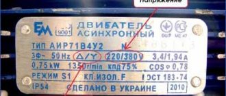
Mains voltages and diagrams of the stator windings of the electric motor
If the electric motor's passport indicates, for example, 220/380 V, this means that the electric motor can be connected to both a 220 V network (winding connection diagram - triangle) and a 380 V network (winding connection diagram - star). The stator windings of an asynchronous electric motor have six ends.
According to GOST, the windings of an asynchronous motor have the following designations: Phase I – C1 (start), C4 (end), Phase II – C2 (start), C5 (end), Phase III – C3 (start), C6 (end).
Rice. 1. Connection diagram of the windings of an asynchronous motor: a – in a star, b – in a triangle, c – execution of the “star” and “delta” circuits on the terminal board.
If the voltage in the network is 380 V, then the stator windings of the motor must be connected in a star configuration. In this case, either all the beginnings (C1, C2, C3) or all the ends (C4, C5, C6) are collected into a common point. A voltage of 380 V is applied between the ends of the windings AB, BC, CA. At each phase, that is, between points O and A, O and B, O and C, the voltage will be √ 3 times less: 380/√ 3 = 220 V.
If the voltage in the network is 220 V (with a voltage system of 220/127 V, which is currently found almost nowhere), the stator windings of the motor must be connected in a “triangle” pattern.
At points A, B and C, the beginning (H) of the previous winding is connected to the end (K) of the subsequent winding and to the network phase (Fig. 1, b). If we assume that between points A and B phase I is switched on, between points B and C – phase II, and between points C and A – phase III, then in the “triangle” scheme the following are connected: the beginning of I (C1) to the end of III (C6) , beginning II (C2) with end I (C4) and beginning III (C3) with end II (C5).
On some motors, the ends of the winding phases are brought out onto the terminal board. According to GOST, the beginnings and ends of the windings are output in the order shown in Figure 1, c.
If it is now necessary to connect the motor windings according to the “star” circuit, the terminals to which the ends (or beginnings) are brought out are connected to each other, and the network phases are connected to the motor terminals to which the beginnings (or ends) are brought out.
When connecting the motor windings in a “triangle”, the terminals are connected vertically in pairs and the network phases are connected to the jumpers. Vertical jumpers connect the beginning of I to the end of phase III, the beginning of II to the end of phase I, and the beginning of III to the end of phase II.
When determining the winding connection diagram, you can use the following table:
Voltage indicated in the motor passport, V
Network voltage, V
Determination of matched terminals (beginnings and ends) of the stator winding phases.
The terminals of the stator windings of the motor usually have standard markings on metal crimp rings. However, these crimp rings are lost. The need then arises to define consistent conclusions. This is done in this order.
First, using a test lamp, pairs of terminals belonging to individual phase windings are determined (Fig. 2).
Rice. 2. Determination of phase windings using a test lamp.
One of the six terminals of the motor stator winding is connected to the network terminal 2, and one end of the test lamp is connected to the other network terminal 3. The other end of the test lamp is alternately touched to each of the other five terminals of the stator windings until the lamp lights up. If the lamp lights up, it means that the two terminals connected to the network belong to the same phase.
Asynchronous motor control
- Methods for connecting an asynchronous electric motor to the power supply:
- direct connection to power supply
- connection from soft starter
- connection from frequency converter
Options for connecting an asynchronous electric motor using a magnetic starter (left), a soft starter (in the middle) and a frequency converter (right). The diagrams are presented in a simplified form. FU1-FU9 - fuses, KK1 - thermal relay, KM1 - magnetic starter, L1-L3 - contacts for connecting to a three-phase alternating current network, M1-M3 - asynchronous electric motors, QF1-QF3 - circuit breakers, UZ1 - soft starter, UZ2 - frequency converter
Direct connection to mains power
The use of magnetic starters allows you to control asynchronous electric motors by directly connecting the motor to an alternating current network.
Using magnetic starters you can implement the following circuit:
- non-reversible start: start and stop;
- reverse start: start, stop and reverse.
The use of a thermal relay makes it possible to protect the electric motor from current values much higher than the rated value.
Non-reversible circuit
Reversible circuit
The disadvantage of direct commutation of the windings of an asynchronous electric motor with the network is the presence of large starting currents when starting the electric motor.
Smooth start of an asynchronous electric motor
In tasks where it is not necessary to adjust the speed of the electric motor during operation, a soft starter is used to reduce starting currents.
The soft starter protects the asynchronous electric motor from damage caused by a sharp increase in energy consumption during starting by limiting the starting currents. The soft start device allows for smooth acceleration and braking of an asynchronous electric motor.
A soft starter is cheaper and more compact than a frequency converter. Used where adjustment of rotation speed and torque is required only during startup.
Frequency control of an asynchronous electric motor
To regulate the rotation speed and torque of an asynchronous motor, a frequency converter is used. The operating principle of a frequency converter is based on changing the frequency and voltage of alternating current.
- Using a frequency converter allows you to:
- reduce the energy consumption of the electric motor;
- control the rotation speed of the electric motor (soft start and stop, speed adjustment during operation);
- avoid overloading the electric motor and thereby increase its service life.
Functional diagram of variable frequency drive
- Depending on the functionality, frequency converters implement the following control methods with an asynchronous electric motor:
- scalar control;
- vector control.
Scalar control
is simple and cheap to implement, but has the following disadvantages - slow response to load changes and a small control range. Therefore, scalar control is usually used in tasks where the load is either constant or varies according to a known law (for example, fan control).
How to determine the beginning and end of a winding in a motor.
In this article I will tell you a way to determine the beginning and end of the winding in an asynchronous three-phase motor.
When might you need this material? Only if you have six wires of the same color in the box and there are no markings on them. Or your motor was connected in delta and you want to be able to connect it in star. I wrote how to do this here. To make it easier to explain the material, let’s first go through the accepted markings of motor winding terminals.
§76. Squirrel-cage induction motor
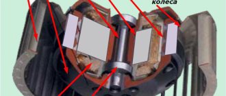
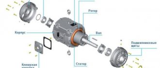
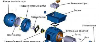
An asynchronous motor with a squirrel-cage rotor (Fig. 249 and 250) consists of the following main parts: a stator with a three-phase winding, a squirrel-cage rotor and a frame. The rotor winding is non-contact (it is not connected to any external circuit), which determines the high reliability of such a motor.
Magnetic system. An asynchronous machine, unlike a direct current machine, does not have pronounced poles. Such a magnetic system is called non-salient pole. The number of poles in a machine is determined by the number of coils in the stator winding and their connection diagram. In a four-pole machine (Fig. 251), the magnetic system consists of four identical branches, through each of which passes half the magnetic flux Фп of one pole; in a two-pole machine there are two such branches, in a six-pole machine - six, etc. Since all the elements of the magnetic system passes an alternating magnetic flux, then not only rotor 1, but
Rice. 249. Asynchronous motor with a squirrel-cage rotor: 1 - frame; 2 - stator; 3 - rotor; 4 — rotor winding rods; 5 — bearing shield; 6 — rotor ventilation blades; 7 - fan; 8 - terminal box
Rice. 250. Electrical diagram of an asynchronous motor with a squirrel-cage rotor (a) and its conventional graphical representation (b): 1 - stator; 2 - rotor
Fig.251. Magnetic field of a four-pole asynchronous machine
Rice. 252. Sheets of the rotor (a) and stator (b)
Rice. 253. Package of assembled stator (a) and stator with winding (b)
and stator 2 is made of sheets of electrical steel (Fig. 252), isolated from one another by an insulating varnish film, scale, etc. As a result, the harmful effect of eddy currents arising in the steel of the stator and rotor during rotation of the magnetic field is reduced. The stator and rotor sheets have open, semi-closed or closed grooves in which the conductors of the corresponding windings are located. In the stator, semi-closed rectangular or oval-shaped slots are most often used; in high-power machines, open rectangular slots are used.
The stator core 1 (Fig. 253, a) is pressed into the cast frame 3 and secured with locking screws. The rotor core is pressed onto the rotor shaft, which rotates in ball bearings mounted in two bearing shields. The air gap between the stator and the rotor is the minimum size allowed from the point of view of assembly accuracy and mechanical rigidity of the structure. In low- and medium-power engines, the air gap is usually a few tenths of a millimeter. This gap ensures a decrease in the magnetic resistance of the machine’s magnetic circuit, and therefore a decrease in the magnetizing current required to create magnetic flux in the engine. Reducing the magnetizing current allows you to increase the power factor of the motor.
Stator winding . It is made in the form of a series of coils of wire of round or rectangular cross-section. The conductors located in the grooves are connected to form a row of coils 2 (Fig. 253, b). The coils are divided into identical groups according to the number of phases, which are placed symmetrically along the circumference of the stator (Fig. 254, a) or rotor. In each such group, all coils are electrically connected, forming one phase of the winding, i.e., a separate electrical circuit. At large values of phase current or when it is necessary to switch individual coils, the phases may have several parallel branches. The simplest element of the winding is a turn (Fig. 254,b), consisting of two conductors 1 and 2, placed in grooves located some distance from each other.
Rice. 254. Location of three-phase winding coils on the stator of an asynchronous motor (a) and a turn of two conductors (b)
torus distance y. This distance is approximately equal to one pole division m, which is understood as the length of the arc corresponding to one pole.
Typically, the turns formed by conductors lying in the same slots are combined into one or two coils. Sometimes they are called sections. They are laid in such a way that each groove accommodates one side of the coil or two sides - one above the other. In accordance with this, a distinction is made between single- and double-layer windings. The main parameter that determines the distribution of the winding among the slots is the number of slots q per pole and phase.
In the stator winding of a two-pole motor (see Fig. 254, a) each phase (A-X; BY; CZ) consists of three coils, the sides of which are located in three adjacent slots, i.e. q = 3. Usually q > 1 , such a winding is called distributed.
The most widespread are two-layer distributed windings. Their sections 1 (Fig. 255, a) are placed in slots 2 of the stator in two layers. The conductors of the stator winding are reinforced in the grooves with textolite wedges 5 (Fig. 255,b), which are placed at the heads of the teeth.
The walls of the groove are covered with sheet insulating material 4 (electric cardboard, varnished cloth, etc.). The conductors lying in the grooves are connected to each other accordingly from the end sides of the machine. The wires connecting them are called frontal parts. Since the frontal parts do not take part in inducing e. etc., they are performed as briefly as possible.
The individual coils of the stator winding can be connected in a star or delta connection. The beginnings and ends of the windings of each phase are brought out to six motor terminals.
Rotor winding. The rotor winding is made in the form of a squirrel cage (Fig. 256,a). It is made of copper or aluminum rods short-circuited at the ends with two rings (Fig. 256, b). The rods of this winding are inserted into the slots of the rotor without any insulation, since the voltage in the short-circuited
Rice. 255. Double-layer stator winding of an asynchronous motor: 1 - section; 2 - groove; 3 - conductor; 4 - insulating material; 5 - wedge; 6 - tooth
Rice. 256. Squirrel-cage rotor: a - squirrel cage; b - rotor with a squirrel cage of rods; c — rotor with a cast squirrel cage; 1 - short-circuit rings; 2—rods; 3— shaft; 4 — rotor core; 5 — ventilation blades; 6 — cast cage rods
that rotor winding is zero. The grooves of a squirrel-cage rotor are usually made semi-closed, and in low-power machines - closed (the groove has a steel rim separating it from the air gap). This shape of the groove makes it possible to strengthen the conductors of the rotor winding well, although it slightly increases its inductive resistance.
In engines with power up to 100 kW, squirrel cage rods are usually obtained by pouring molten aluminum into the grooves of the rotor core (Fig. 256, c). Together with the rods of the squirrel cage, the end short-circuit rings connecting them are also cast.
Aluminum is suitable for this purpose, since it has low density, fairly high electrical conductivity and melts easily.
Typically, engines have fans mounted on the rotor shaft. They provide forced ventilation of the heated parts of the machine (windings and steel of the stator and rotor), allowing greater power to be obtained from the engine. In engines with a squirrel-cage rotor, the fan blades are often cast together with the side rings of the squirrel cage (see Fig. 256, c).
Asynchronous motors with a squirrel-cage rotor are simple in design and reliable in operation. They are widely used to drive metalworking machines and other devices that start working without load. However, the relatively low starting torque of these motors and the large starting current do not allow them to be used to drive machines and mechanisms that must be put into operation immediately under a large load (with a large starting torque). Such machines include lifting devices, compressors, etc.
You can increase the starting torque and reduce the starting current by performing a squirrel cage with increased active resistance. In this case, the engine will have increased slip and large power losses in the rotor winding. Such motors are called motors with increased slip (designated AC). They can be used to drive machines that operate for a relatively short time. On e. p.s. AC these motors (with slip up to 10%) are used to drive compressors that operate periodically for short periods of time when the pressure in the air tanks decreases below a certain limit.
Motors with increased starting torque. Squirrel-cage asynchronous motors with increased starting torque have a special rotor design (designated AP). These include double squirrel cage motors and deep slot motors.
Rotor 3 (Fig. 257,a) of a double squirrel cage motor has two short-circuited windings. Outer cage 1 is the starting cage. It has high active and low reactance. Inner cage 2 is the main rotor winding; on the contrary, it has insignificant active and high reactance. At the initial moment of start-up, the current flows mainly through the outer cage, which creates a significant torque. As the rotational speed increases, the current flows into the inner cage, and at the end of the starting process, the machine operates like a conventional squirrel-cage motor with one (inner) cage. The displacement of the current into the outer cell at the initial moment of start-up is explained by the action, e. d.s. self-induction induced in the rotor conductors. The lower the conductor is located in the groove, the greater the magnetic leakage flux 6 it is covered and the greater the e. d.s. self-induction is induced in it (Fig. 257, c), therefore, the greater the inductive resistance it will have.
The displacement of current into the upper conductors of the rotor has a strong effect when the rotor is stationary, when the frequency of the current induced in both cells of the rotor is high. At the same time, inductive
Rice. 257. Design of rotors of asynchronous motors with increased starting torque: with a double squirrel cage (a), with deep grooves (b) and sections of their grooves (c and d)
The resistances of both cells are much greater than the active ones and the current is distributed between them in inverse proportion to their inductive resistances, i.e., it passes mainly through the outer cell with a high active resistance. As the rotation speed of the rotor increases, the frequency of the current in it will decrease (the rotating magnetic field will cross the rotor conductors with a lower frequency), and the current will begin to pass through both cells in accordance with their active resistances, i.e., mainly through the inner cell .
Thus, the process of starting a motor with a double squirrel cage is similar to the process of starting an asynchronous motor with a wound rotor, when at the beginning of the start an additional active resistance (starting rheostat) is introduced into the rotor winding circuit, and as acceleration progresses, this resistance is removed. In the same way, in the motor under consideration, the current at the beginning of the start passes through the outer cage with high active resistance, and then, as it accelerates, it gradually passes into the inner cage with low active resistance.
To increase the active resistance of the starting cage, its rods are made of manganese brass or bronze. The rods of the working cage are made of copper, which has low resistivity, and their cross-sectional area is larger than that of the starting cage. As a result of this, the active resistance of the starting cell increases by 4-5 times compared to the working one. Between the rods of both cells there is a narrow gap 5, the dimensions of which determine the inductance of the working cell. A two-cage engine is 20-30% more expensive than a squirrel-cage engine of conventional design. To simplify the rotor manufacturing technology, two-cage engines of small and medium power are made with a cast aluminum cage.
The operation of motors with deep slots (Fig. 257, b) is also based on the use of the phenomenon of current displacement. In these engines, the squirrel cage rods 4 are made in the form of narrow copper bars placed in deep grooves of the rotor 3 (the height of the groove is 10-12 times greater than its width). The lower layers of the rods, located further from the surface of the rotor, are covered by a significantly larger number of magnetic lines of leakage flux 6 than the upper ones (Fig. 257, d), therefore they have many times greater inductance. At the beginning of the start-up, as a result of the increased inductive reactance of the lower parts of the rods, the current passes mainly through their upper parts. In this case, only a small part of the cross-section of each rod is used, which leads to an increase in its active resistance, and consequently, to an increase in the active resistance of the entire rotor winding.
As the rotor speed increases, the displacement of current into the upper parts of the rods decreases (for the same reason as in a motor with a double squirrel cage), and after the start is completed, the current is evenly distributed over their cross-sectional area.
Conclusions of an asynchronous motor. Marking of asynchronous motor terminals
There are various markings for the terminals of the motor windings. Domestic markings from C1 to C6 and international, which you see in the figure.
Nowadays, both markings are found, but for “training” we will use new designations as they are more descriptive. Earlier, I already said that the beginning and end of the windings are absolutely conditional concepts, the main condition that plays an important role is such a connection of the windings when the magnetic fluxes are not directed in the opposite direction. If two identical flows are sent counter, they seem to destroy each other. We need to obtain a consistent direction of magnetic fluxes. The motor has three windings. Roughly speaking, a motor is a transformer with three windings and a stator core. Thus, the windings in the motor are connected by a magnetic flux that flows through the stator, and it is created by a current that flows through the windings. The rotor is just a pleasant “yummy”, the presence of which allows you to convert electrical energy into mechanical energy.
Completing of the work. Marking of stator winding terminals
Marking of stator winding terminals
Determination of the same terminals of the phases of the stator windings and the study of the start-up are carried out on an asynchronous three-phase micromotor with a squirrel-cage rotor.
The work begins with determining whether the output ends belong to the same phase. To do this, it is necessary to find the circuit of each phase using a voltmeter connected in series with the expected phase terminals (Fig. 10). The deviation of the voltmeter to the value of the mains voltage indicates that the terminals are determined correctly. After this, they begin to determine the terminals of the same name (beginnings and ends) of the stator phase windings. Correct marking of the terminals of the same name is a necessary condition for obtaining a circular rotating magnetic field necessary for normal operation of the engine. The beginnings of the phases are designated: and the corresponding ends: ; in modern asynchronous machines, the beginnings of the phases are marked differently: the beginnings of the phases, and the corresponding ends
.
To determine the terminals of the stator phase windings of the same name, it is necessary to connect one of the phases (for example, ) to the alternating current network, and connect a voltmeter to the other two series-connected (Fig. 11) phases. When these phases are connected with opposite terminals (for example, according to the diagram), a voltmeter connected to terminals and will show some voltage (in laboratory conditions it is insignificant - up to 10 V). If identical terminals are connected together (for example, according to a circuit), then the voltage between the points will be zero.
Having marked two phases connected in series, disconnect them. Then one of the already marked phases (for example,) is connected to the network, and the other marked phase ( ) is connected in series with the first phase ( ). The external terminals of these windings connected in series are connected to a voltmeter. According to the voltmeter readings, taking into account the already accepted markings, the beginning and end of the first phase ( ) are determined.
Starting the engine by switching the stator windings
from star to triangle
To start the engine by switching, a circuit is assembled according to Fig. 12 without an ammeter. After connecting the motor to the network, you need to make sure that it rotates normally. Then an ammeter is connected to measure the linear starting current (see Fig. 12).
As is known from theory, the linear starting current when the stator windings are connected to a star is three times less than when connected directly to a delta. However, due to the inertia of the moving system of the device, during measurements, the ratio between the currents will be slightly different from the actual one.
Reversing an asynchronous motor is done by switching the linear wires of any two phases. This should be tested experimentally.
Taking performance characteristics
Operating characteristics are the dependences of power consumption, stator current, rotational speed, slip, torque, efficiency and useful power at constant values of voltage at the stator terminals and frequency:
at and .
To measure the performance characteristics, assemble the circuit in Fig. 13. The test bench has a motor with marked outputs of the stator winding phases, an electromagnetic brake for carrying out the load, a rotation speed meter, and a set of measuring instruments.
The engine test circuit provides for direct measurement of rotation speed. The measurement is carried out as follows. A mechanical breaker is installed on the motor shaft (Fig. 13), which, using the MP contact, interrupts the electrical power circuit of the revolution counter winding at each revolution of the motor shaft.
The engine rotor speed is determined by the formula, rpm,
where is the number of pulses that the counter shows;
the time during which the electric stopwatch is counted (taken by pressing the stopwatch button once, approximately 10 s and recorded with an accuracy of hundredths of a second);
takes into account the error possible at the beginning of the countdown.
Performance characteristics are measured at rated (stator windings connected in a triangle) and reduced (stator windings connected in a star) voltages on the phases of the motor stator winding, loading it with an electromagnetic brake from idle mode to line current values exceeding the nominal ones by 20-30%. The experimental data are entered in Table 13.
Table 13
| Observations | Computations | ||||||||||
| ¦2 | |||||||||||
| IN | A | W | N×m | imp | With | rpm | % | Hz | — | W | % |
Marking of stator winding terminals
Determination of the same terminals of the phases of the stator windings and the study of the start-up are carried out on an asynchronous three-phase micromotor with a squirrel-cage rotor.
The work begins with determining whether the output ends belong to the same phase. To do this, it is necessary to find the circuit of each phase using a voltmeter connected in series with the expected phase terminals (Fig. 10). The deviation of the voltmeter to the value of the mains voltage indicates that the terminals are determined correctly. After this, they begin to determine the terminals of the same name (beginnings and ends) of the stator phase windings. Correct marking of the terminals of the same name is a necessary condition for obtaining a circular rotating magnetic field necessary for normal operation of the engine. The beginnings of the phases are designated: and the corresponding ends: ; in modern asynchronous machines, the beginnings of the phases are marked differently: the beginnings of the phases, and the corresponding ends.
To determine the terminals of the stator phase windings of the same name, it is necessary to connect one of the phases (for example, ) to the alternating current network, and connect a voltmeter to the other two series-connected (Fig. 11) phases. When these phases are connected with opposite terminals (for example, according to the diagram), a voltmeter connected to terminals and will show some voltage (in laboratory conditions it is insignificant - up to 10 V). If identical terminals are connected together (for example, according to a circuit), then the voltage between the points will be zero.
Having marked two phases connected in series, disconnect them. Then one of the already marked phases (for example,) is connected to the network, and the other marked phase ( ) is connected in series with the first phase ( ). The external terminals of these windings connected in series are connected to a voltmeter. According to the voltmeter readings, taking into account the already accepted markings, the beginning and end of the first phase ( ) are determined.
Starting the engine by switching the stator windings
from star to triangle
To start the engine by switching, a circuit is assembled according to Fig. 12 without an ammeter. After connecting the motor to the network, you need to make sure that it rotates normally. Then an ammeter is connected to measure the linear starting current (see Fig. 12).
As is known from theory, the linear starting current when the stator windings are connected to a star is three times less than when connected directly to a delta. However, due to the inertia of the moving system of the device, during measurements, the ratio between the currents will be slightly different from the actual one.
Reversing an asynchronous motor is done by switching the linear wires of any two phases. This should be tested experimentally.
Taking performance characteristics
Operating characteristics are the dependences of power consumption, stator current, rotational speed, slip, torque, efficiency and useful power at constant values of voltage at the stator terminals and frequency:
at and .
To measure the performance characteristics, assemble the circuit in Fig. 13. The test bench has a motor with marked outputs of the stator winding phases, an electromagnetic brake for carrying out the load, a rotation speed meter, and a set of measuring instruments.
The engine test circuit provides for direct measurement of rotation speed. The measurement is carried out as follows. A mechanical breaker is installed on the motor shaft (Fig. 13), which, using the MP contact, interrupts the electrical power circuit of the revolution counter winding at each revolution of the motor shaft.
The engine rotor speed is determined by the formula, rpm,
where is the number of pulses that the counter shows;
the time during which the electric stopwatch is counted (taken by pressing the stopwatch button once, approximately 10 s and recorded with an accuracy of hundredths of a second);
takes into account the error possible at the beginning of the countdown.
Performance characteristics are measured at rated (stator windings connected in a triangle) and reduced (stator windings connected in a star) voltages on the phases of the motor stator winding, loading it with an electromagnetic brake from idle mode to line current values exceeding the nominal ones by 20-30%. The experimental data are entered in Table 13.
Table 13
| Observations | Computations | ||||||||||
| ¦2 | |||||||||||
| IN | A | W | N×m | imp | With | rpm | % | Hz | — | W | % |
The beginning and end of the motor windings
Well, let's get started. Before you begin the procedure, you need to prepare. For this you will need:
- multimeter or incandescent lamp (preferably, of course, a multimeter)
- wire markers
- knowledge of safety precautions as you will be working with dangerous voltage
- regular power plug with wire
- something you will use to connect the wires when you start looking for the winding leads
- Well, the material of this article.
As markers, you can use cambrics, paper with erasers, colored electrical tape and regular permanent markers, in general, anything that will allow you to mark the conclusions. You will need six markers on which you will write the beginning and end of the windings.
The first step is to determine the motor windings
The names of the windings are also absolutely arbitrary. Although, if we take into account such a concept as phasing, then correct inclusion gives an accurate idea of in which direction the motor shaft will rotate and nothing more. Set the multimeter to dialing mode, apply one probe to any of the six wires, and use the second probe to find the end that will be dialed. And you mark this pair of ringing ends. Let these be U1 and U2. Four ends remain. Repeat the operation and mark another pair again. Let these be V1 and V2. There are still a couple of ends left, you check them just in case to be sure that the winding is in good condition and also mark them with the remaining markers W1 and W2. Now you have three windings and you know their conclusions. But you don’t know where the beginning and where the end of each winding is. In other words, you do not know which way the magnetic fluxes of these windings are directed according to the existing markings, since they are now random.