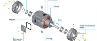
Rules for disassembling electric motors
- start disassembling the electric motor only after disconnecting it from the power supply: the wires must be removed or the plug must be removed from the socket.
- There may be capacitors in the motor control circuit , so do not forget to discharge their terminals.
- Disassembly must be carried out without distortions and impacts strictly in a certain sequence.
- The engine should be disassembled only after disconnecting from the mechanism. which he rotates.
- Be careful when working and do not bend the shaft, damage the windings, brushes, commutator, etc.
- Before starting to disassemble the electric motors, I recommend marking the locations of the covers relative to the housing with marks, and be sure, if there is no key, to mark the position of the fan on the shaft. If installed in a position other than the one the fan was in, the shaft will become unbalanced.
An alternative to costly disposal
Specialized scrap metal collection points will help you save money and time, as well as profitably get rid of non-working engines. It is important that the selected company has licenses from the Department of Natural Resources and Environment of the Russian Federation. These documents certify the organization’s right to work with scrap non-ferrous and ferrous metals, as well as waste.
A licensed collection point can buy the equipment assembled, but the price for 1 kg of scrap will be minimal. After the purchase, specialists will disassemble the electric motor into copper, aluminum, stainless steel and dispose of the remaining equipment. If you want to earn more money, you will have to put in a little effort: figure out how to disassemble the electric motor into copper, remove it and, if necessary, burn the non-ferrous metal.
How to disassemble an asynchronous electric motor
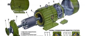
- Unscrew the screws and remove the fan protective casing (number 1 in the figure).
- We make notes on the asynchronous electric motor, as described above.
- Remove the fan , which is held on by one or two bolts (2).
- We unscrew three, four or more bolts that hold the front and rear covers (3 and 5).
- The most difficult step is to remove the back cover of an asynchronous motor, in which the shaft rotates in a bearing. For small electric motors this is easy to do by prying a screwdriver between the housing and the cover on all sides. In medium-sized electric motors, the cover is removed by hitting it with a hammer through a metal rod, only you need to hit it one by one from all sides so that the cover goes without distortions. To make the process easier, you can heat the lid, but not the shaft. Just never hit the ears to secure them with bolts, otherwise you will break them. The covers of more powerful engines for industrial use are pressed using a screw puller or press.
If there are special holes for the release bolts, then to remove the cover it is necessary to evenly screw them into the release holes, avoiding distortion of the bearing shields.
After the back cover is removed, all that remains is to carefully remove the rotor with the front cover from the stator.
Synchronous AC or DC motors are much easier to disassemble, without the need to knock out anything. The main thing is to disassemble the case in which it is installed.
What engines scrap can be donated?
Collection points for scrap metal and secondary raw materials accept the following types of electric motors:
- brushless steppers installed on milling machines and industrial equipment;
- DC servo motors suitable for robotic machines;
- DC motors (DC motors) used in powered tools, toys and appliances;
- linear, used in electric transport, cargo, piling and cutting special equipment;
- motor-compressors that combine the functions of an electric drive and a compressor, therefore used in household appliances and electric vehicles.
If you don’t know how to quickly disassemble an electric motor into copper, contact a specialized company. Its employees will come to your home and dismantle the equipment, as well as carry out related work.
How to disassemble the electric motor of a drill, hammer drill and other power tools
In the household, motors in power tools most often break down. To do it yourself, you will most likely need to replace the graphite brushes or clean the motor commutator. In order to correct this or another malfunction, it is necessary to disassemble a non-working or poorly functioning angle grinder, hammer drill, etc.
Disassembly order:
- Unplug from the socket.
- We unscrew all the screws and remove one half of the plastic case. The other will contain an electric motor.
- In order to change the brushes , you need to unscrew the brush holder bolt or remove the pressure spring.
- If you need to remove the commutator, first remove the brushes, and then unscrew the bolts securing the bearing.
- We lift the entire electric motor and carefully remove the armature from the stator winding.
Rotor balancing
In order for the power tool to work as efficiently as possible after repair, you will need to do balancing. Since all work is performed at home, certain recommendations must be followed. Rewinding an electric motor with your own hands is quite simple; balancing it will be much more difficult.
- Pick up two steel blades. They should be even and smooth.
- These blades must be installed parallel and attached to a rigid base.
- It is necessary to maintain a distance between them that is equal to the size of the rotor.
- You place a rotor on these steel blades and watch how it moves.
- The anchor will definitely start to rotate, the heaviest part will be at the bottom.
- It is necessary to shift the center of gravity to the axis of the rotor, securing loads on it.
Dismantling electric motors from a car
different brushed electric motors in a car They are understood differently. The simplest ones use ordinary magnets instead of a stator winding. Therefore, voltage is applied only to the collector. To disassemble, you will need to simply disassemble the body, which can be glued from 2 halves, riveted, or connected using bolts or cogs.
Disassembly of more powerful electric motors of a car, such as a starter, is always described in detail in the operating manual for your car model.
HOW TO REMOVE THE WIRE FROM THE MOTOR
The need to remove the copper wire from the stator core of an electric motor arises in two cases:
- if the winding has become unusable - “burnt out” and requires repairs - wind a new one
- an electric motor, for any of many possible reasons, must be disposed of and it would be extremely unreasonable not to remove the copper wire from the stator, the weight of which, even for an average-sized engine, is close to 1 kilogram.
While doing this, for the first time, I immediately decided for myself that I would not take a sledgehammer and a gas cutter as assistants, but would use less radical means as a tool for disassembly.
First of all, I pry up with a powerful awl and cut with side cutters the thick threads soaked in varnish that tighten the copper wire of the winding.
I remove them, then use a screwdriver to separate the internal wire harnesses from the external ones and remove the dielectric spacer separating them.
At the next stage, you need to do the same with the other side and get a “picture” like this, and only after that start cutting the copper wire with side cutters (the cut places will not have time to “fluff” so much and it will be easier to pull out the wires). Can be sawed with a hacksaw. The bundles should be cut in half and only on one side.
Using a small hammer, on both sides, carefully tap the places where the wire bundles enter the grooves of the core.
First, one edge of the cut bundles is pulled out using a powerful screwdriver, which is used as a lever.
But before this, it is necessary to press the wires in the cut areas more tightly together. You can do it with your fingers, but using pliers will be more accurate.
One edge of the harness has come out, and we take out the second with gloved hands, holding the free end firmly and firmly resting against the metal core of the stator with our booted feet.
It took less than half an hour to remove the copper wire from the core. The result is obvious. We have 600 grams of scrap copper available. All that remains is to light a very small fire in some suitable place and burn the varnish sheath of the wire. Donating even this amount of copper will make it possible to purchase an expensive microcircuit.
Electric motor assembly
Always reassemble in reverse order. To avoid confusion with commutator electric motors, I always recommend taking photographs after each stage of disassembly.
With asynchronous ones everything is simpler:
- We insert the rotor with the front shield.
- We fasten the front cover with bolts to the body.
- We place the shaft stop for large electric motors through the board to the wall and carefully hammer in the back cover. Do not use only metal for driving, because the lid made of silumin or other brittle metal may crack. I hammer the cap in with the back of the insulating side of a screwdriver in smaller motors or with the handle of a hammer in larger ones. Try to score with gentle hits on the marks and make sure that there is no distortion.
Source: jelektro.ru
Calculation table for copper in electric motors
| Electric motors 4A, 4AM weight, kg with number of pole pairs | ||||||||
| power, kWt | 2/3000 rpm | 4/1500 rpm | 6/1000 rpm | 8/750 rpm | ||||
| engine | copper, kg | engine | copper, kg | engine | copper, kg | engine | copper, kg | |
| 0,06 | 3,3/3 | 0,419/0,485 | ||||||
| 0,09 | 3,3/3 | 0,426/0,440 | 3,3/3 | 0,542/0,534 | ||||
| 0,12 | 3,3/3 | 0,542/0,534 | 4,5/4,3 | 0,50/0,48 | ||||
| 0,18 | 4,5/4,3 | 0,42/0,38 | 4,5/4,3 | 0,55/0,63 | 6,3/6,1 | 0,64/0,62 | ||
| 0,25 | 4,5/4,3 | 0,45/0,44 | 6,3/6,1 | 0,59/0,61 | 6,3/6,1 | 0,83/0,85 | 15,1/14 | 0,95 |
| 0,37 | 6,3/6,1 | 0,58/0,55 | 6,3/6,1 | 0,59/0,61 | 15,1/14 | 0,97 | 17,5/17,1 | 1,16 |
| 0,55 | 6,3/6,1 | 0,60/0,62 | 15,1/14 | 0,92/0,93 | 15,1/14 | 1,08/1,11 | 20,0/19,5 | 1,33/1,34 |
| 0,75 | 15,1/14 | 0,91/0,93 | 15,1/14 | 0,94/0,97 | 17,5/17,1 | 1,24/1,19 | 25,5 | 1,58/1,62 |
| 0,9 | 25,5 | 1,59/1,53 | ||||||
| 1,1 | 15,1/14 | 0,96/0,92 | 17,5/17,1 | 1,36/1,35 | 20,0/19,5 | 1,58/1,51 | 25,5 | 1,91/1,9 |
| 1,2 | 25,5 | 1,91/1,87 | ||||||
| 1,5 | 17,5/17,1 | 1,59/1,51 | 20,0/19,5 | 1,49/1,44 | 28,7/25,5 | 1,95/1,92 | 42,0/40,5 | 2,28/2,25 |
| 1,7 | 28,7/25,5 | 1,88/1,90 | 42,0/40,5 | 2,56/2,49 | ||||
| 2,2 | 20,0/19,5 | 1,82/1,74 | 28,7/25,5 | 1,92/1,87 | 42,0/40,5 | 2,28/2,25 | 56,0/54,0 | 3,04/3,16 |
| 2,4 | 28,7/25,5 | 1,92/1,93 | ||||||
| 3 | 28,7/25,5 | 2,51/2,6 | 36,0/36,4 | 2,80/2,95 | 56,0/54,0 | 3,05/2,99 | 56,0/54,0 | 3,45/3,65 |
| 3,5 | 28,7/25,5 | 2,50/2,42 | ||||||
| 4 | 36,0/36,4 | 3,76/3,64 | 42,0/40,5 | 2,81/2,95 | 56,0/54,0 | 3,42/3,42 | 77,0/72,0 | |
| 5,5 | 42,0/40,5 | 4,12/4,0 | 56,0/54,0 | 3,49/3,53 | 77,0/72,0 | 4,35/4,38 | 93,0/90,0 | |
| 7,5 | 56,0/54,0 | 4,79/4,71 | 77,0/72,0 | 5,44/5,20 | 93,0/90,0 | 4,94/5,07 | 135,0 | 7,3 |
| 11 | 93,0/90,0 | 93,0/90,0 | 6,09/6,26 | 135,0 | 7,9/8,1 | 160,0 | 8,4/8,5 | |
| 15 | 130,0 | 9,0/9,2 | 135,0 | 9,9/10,9 | 160,0 | 9,2/9,3 | 195,0 | 11,7/11,6 |
| 18,5 | 145,0 | 9,7/9,6 | 160,0 | 11,3/11,2 | 195,0 | 12,1/12,2 | 270,0 | 13,5/13,1 |
| 22 | 165,0 | 12,5/12,3 | 175,0 | 13,2 | 270,0 | 15,9/15,8 | 310/300 | 14,5 |
| 30 | 185,0 | 14,8/14,4 | 195,0 | 14,5/14,4 | 310/300 | 16,8/16,6 | 355 | 19,4/19,3 |
| 37 | 255/250 | 19,7/19,5 | 270 | 17,6/18,1 | 355 | 21,3/21,6 | 490 | 22,7/23,5 |
| 45 | 280/275 | 21,0/20,7 | 310/300 | 20,5/19,5 | 490 | 26,6 | 535 | 26,8/25,8 |
| 55 | 355/350 | 24,8/24,7 | 355 | 25,8/25,1 | 535 | 27,0/27,9 | 785 | |
| 75 | 470 | 33 | 490 | 39,6/38 | 785 | 835 | ||
| 90 | 510 | 34,8/35,0 | 535 | 43,8/40,0 | 835 | 875 |
The procedure for disassembling and assembling the AIR63A2 asynchronous motor
Engine disassembly should be carried out in the following sequence:
remove the key and, if there is a second working end of the shaft, remove the key;
Unscrew the casing mounting bolts and remove the casing.
remove the spring thrust ring and remove the fan using a puller;
unscrew the bolts securing the bearing shields;
unscrew the bolts securing the bearing caps;
remove the bearing cover and bearing shield;
remove the rotor along with the bearings, bearing caps and bearing shield;
It is necessary to ensure that the frontal parts of the stator winding and rotor surfaces are not damaged.
and parts installed on the rotor.
unscrew the bolts securing the bearing caps;
remove the bearing cover, bearing shield, and spring from the rotor
Care must be taken not to damage the bearing cover underneath.
remove the thrust spring ring;
remove the bearings using a special puller.
Care must be taken not to damage the gaskets.
The engine assembly must be carried out in the reverse order according to the diagram.
For positioning inner bearing caps during assembly
For bearing units, it is recommended to use mounting studs.
After completing assembly, it is necessary to check the insulation resistance of the stator windings and circuit
thermistors relative to the housing and between the windings, as well as ease of rotation of the rotor by hand.
Disassemble the terminal box in the following sequence.
Unscrew the screws securing the terminal box cover and remove it;
unscrew the bolts securing the clamping flange and remove it;
remove the seal and washers from the flange;
unscrew the bolts securing the flange and remove it;
Care must be taken not to damage the gasket.
Unscrew the fastening elements of the cable lugs on the terminal panel.
| Change |
| Sheet |
| Document no. |
| Signature |
| date |
| Sheet |
| UTZhT 14044811150114 |
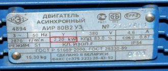
1.7 Testing the AIR63A2 electric motor. During installation, commissioning and operation, electric motors are tested to determine the possibility of their energization and reliable trouble-free operation.
To begin acceptance tests, it is necessary to conduct an external inspection of the electric motor. This checks:
– compliance of engine nameplate data with design data and technical specifications;
General rules for repairs
Basic safety requirements for repair work with angle grinders.
- The grinder, like any power tool, has a cable for connecting to the network. When performing repair work disconnect the plug from the socket to prevent electric shock.
- The tool used for repairs must be in good condition . Working surfaces should not be damaged and securely fastened in devices for holding the tool in the hands. The devices themselves should not create inconvenience to the user performing repair work.
- Some parts of grinders may have sharp edges and burrs. Working with gloves that will protect your hands from direct contact with potentially traumatic parts will help prevent the possibility of injury
- When impregnating the stator windings, fire safety requirements must be observed , since the varnishes used belong to the category of flammable liquids. The use of open fire (smoking and the like) is not allowed. It is better to carry out work in a separate isolated room with a fire extinguisher.
Disassembly procedure for an asynchronous motor with a squirrel-cage rotor
Disassembly of the electric motor must be carried out in the following order:
• wipe the engine from dirt, oil and dust;
• disconnect all supply wires from the machine, having previously marked them;
• remove the end caps of the bearings;
• remove grease from bearings;
• remove the bearing shields using release bolts;
• remove the rotor from the frame, having previously laid a press sheet, 0.5 - 1.5 mm thick, between the rotor and stator to protect the windings from scratches and damage;
• when disassembling the electric motor, ball bearings should be removed only if they are faulty for replacement.
After the necessary work has been completed, the electric motor is assembled in the reverse order of disassembly, and the following is checked:
• condition of the surface of the shaft journals,
• gaps between the iron spaces during the final tightening of the bolts securing the panels,
• rotor run-up in the axial direction,
• free rotation of the rotor.
When disassembling and assembling, you must use only tools specifically designed for this work, and when removing any parts, put all small fasteners in place - bolts, nuts, washers, screws, etc.
After repairing the electric motor, carefully inspect it, test it and test it in action, and you should:
• check the machine connection diagram,
• check the correct connection of the windings in the terminal box,
• inspect the condition of the contacts,
• measure the insulation resistance; the insulation resistance must be at least 1.5 MOhm,
• check the presence of lubricant and its brand,
• test the electric motor at idle for 1 hour.
Repair, preparation for work, necessary tools
Multimeter Zubr. Photo 220Volt
Before carrying out repair work, diagnostics are carried out in order to identify parts and assemblies due to which the angle grinder cannot function normally. The electrical part of the angle grinder is inspected visually to find traces of surface burning in places of short circuit. If, after inspection, there are no obvious signs of malfunction, the electrical part is checked by ringing using special instruments (multimeter, short circuit indicator, and others). After finding and analyzing the damage, a method for eliminating it is adopted.
There are two main ways to repair a stator yourself:
- The burnt stator is removed from the angle grinder body. An identical device to the failed one is purchased from a specialized store and used in an angle grinder instead.
- The burnt winding is removed from the core body and a new one is wound, corresponding to the old one in the number of turns and wire diameter.
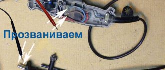
Calling and rewinding
If the cause of the breakdown of the angle grinder is a burnt out stator, a test will determine in more detail which part of it is involved. If there are defects in the coil windings, some users rewind new ones themselves. For a detailed description of the production of such work, follow the links “How to ring the stator of an angle grinder” and “Rewinding the stator of an angle grinder with your own hands.”
Replacement
For the angle grinder model DWT in the next video, a new stator was purchased to replace the burnt one . The new stator was positioned as a unit from a grinder of this model. before removing the faulty stator from the housing is described in detail When examining the appearance of the purchased new and old stators, some differences were observed . However, after assembly and testing for functionality, it turned out that they have practically no effect on the operation of the angle grinder.
Burnt out, rewind
The author of the following video from a state neighboring Russia, having difficulty purchasing a new stator instead of the Russian-made Interskol model burnt out by an angle grinder, decided to rewind it himself . Here it is important to pay attention to the experience that the author gained in the process of rewinding the wire. Do not loosen its tension, otherwise the coil will not be able to fit into the recesses of the stator. The second time the winding was successful.
The varnish impregnation described during the repair should not be copied one to one. Because ordinary wood varnish does not have the necessary electrical insulating properties. If it is difficult to choose an impregnating agent, it is better to use a material based on epoxy resin, which is easy to find. The quality of impregnation will improve if the stator is heated, rather than waiting until the varnish stops penetrating into the winding.
Bosch, replacement
In the next video, the author repairs a Bosch model angle grinder . Working in a heavily dusty atmosphere, of course, can cause severe wear on the commutator lamellas, but this should not be taken as a definite cause of failure of the stator windings. Here you should also consider other operating conditions (overload, operating time, etc.).
The author's diagnosis is in the nature of fortune telling on coffee grounds. A sharp change from a burnt-out rotor, which turned out to be still fully operational, to burnt insulation on a stator that was truly out of order, indicates a lack of a systematic approach to repair work.
During disassembly of the angle grinder, the stator is released from the housing under the influence of strong hammer blows. Although it is made of wood, strong enough impacts can cause damage to the protruding parts of the body.
Why not immediately make the stator output ends of normal length remains a mystery. The author does the same, very labor-intensive job twice without really explaining the reasons.
How to disassemble an electric motor? 7 basic rules for disassembly
When disassembling you need to follow several rules :
- Start work only after disconnecting the engine from the network and take measures to prevent it from turning on: remove the plug from the socket, turn off the circuit breaker, switch. Hang a poster on the handle of the switch or switch: “Do not turn on! People are working!
- The power cable is disconnected from the barno first. If the motor is installed in a production room, the cable cores are closed together.
- If there are capacitors in the electric motor circuit, they are discharged immediately after the power is turned off.
- For disassembly, the engine is disconnected from the mechanism that it rotates.
- If the engine has to be removed from the foundation, and metal plates are placed under its feet to ensure its alignment with the actuator, then they must be left in place in the same order. But even in this case, checking and adjusting the alignment will be required .
- You need to remember the disassembly order exactly..
- When removing the housing covers with bearings, put marks on them so as not to disturb their relative position. When removing the fan from the shaft, you must do the same, otherwise the balancing will be disrupted .
Defective units
Defects of electric motor components and parts are carried out starting with external inspection and pre-repair tests and continue until the end of detailed disassembly. During the defect detection process, the necessary measurements and tests are carried out to reveal hidden defects.
Based on the defects, a repair card and a defect sheet are drawn up. Repair cards contain a description of defects and the results of tests and measurements of the main parts of electric motors. They are stored centrally and used for general control of repairs, accumulation and generalization of statistical data.
Defect sheets must contain detailed and clear information about damage and malfunctions not only of each of the parts to be repaired, but also of all its defective parts. In addition, the statement indicates the type and brief content of the necessary repairs. The defect map is the source document for drawing up technological documentation and, in particular, route maps for repairing parts.
Source
Disassembling an asynchronous electric motor
The disassembly procedure is as follows:
- Remove the fan protective casing by unscrewing the screws securing it to the rear engine cover.
- Remove the fan, marking its position on the shaft.
- Unscrew the bolts securing the covers to the body, first making marks. The most reliable way to fix the position of the covers is through marks made with a file or deep scratches in the paint right down to the metal. Marks made with a marker are erased with hands stained with grease.
- Remove the front or rear cover from the engine housing. The rotor remains in the opposite cover.
- Remove the remaining cover along with the rotor.
- If necessary, remove the rotor shaft from the bearing in the cover.
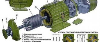
The device of an asynchronous electric motor
Removing the covers from the motor housing is a difficult operation. For low-power motors, a screwdriver is driven into the groove between them at an angle using a hammer. The impact locations are constantly alternating, moving evenly in a circle around the lid. The force of the blows is calculated so as not to break the body if it is made of silumin. Instead of a screwdriver, you can use a soft metal drift. Do not hit the attachment points, they will break .
For powerful motors, screw pullers . Some engines have holes for release bolts, in which case the covers are pressed together with their help. The bolts are screwed in evenly to avoid distortions.
To remove the second cover from the rotor, you can use a puller. But you can simply knock the rotor out of it. To do this, the lid is fixed in a horizontal position on a rigid base so that the rotor rotates freely in it. The height between the lower end of the shaft and the ground is chosen so that after leaving the bearing the rotor does not fall from a great height and is damaged.
The shaft is struck with a hammer through a copper or brass plate. The best spacer between the hammer and the shaft is a block of wood.
Assembly is carried out in reverse order. The covers are attached to the body either by alternately tightening the bolts or by hitting them with a mallet. In any case, uniform installation into the seat is ensured, without snagging or distortion. Before assembly, you need to combine the marks previously applied before disassembly with each other. It will no longer be possible to turn the cover when it is in place .
If misalignment is suspected or resistance to assembly is detected, the cover is again removed and inspected. Once the reason preventing the assembly has been eliminated, it continues.
Principles of stator rewinding
The electromagnetic field of the stator is created using three-phase rewinding. A certain number of coils connected to each other are attached to the grooves of the electric motor.
Options for rewinding the stationary part of electric motors depend on the type of insulation, the choice of which is determined by the following parameters:
- maximum voltage indicator;
- permissible rewind temperature value;
- dimensions and type of groove;
- type of winding.
Depending on the method of placing the coils in the stator slots, the motor is rewinded in one or two layers. Copper cable is used as the winding material.
Electric motor scrap price
Prices for scrapping electric motors are approximately 20 rubles/kg - the average market price in Russia. This means that unassembled electric motors can be brought to the collection point - they are hung and charged 20 rubles/kg, which, in principle, is also not bad, because some even manage to sell electric motors as scrap ferrous metals, according to.
Electric motors for scrap
The price for scrap electric motors may depend on: the number of motors, the amount of work that needs to be done to crush the electric motor housing and perform the separation of non-ferrous and ferrous metals.
If there are many engines, then it is more cost-effective to separate copper and cast iron (electric motor housing). To do this, you can hire a person who will chop the hulls with a sledgehammer, and another will extract copper. It all depends on the number of engines. If there are a lot of them, then the work may take several days, while wage costs will be scanty - 1500-2000 rubles per day, and the income received from copper and cast iron will ultimately more than cover all costs.
Electric motor scrap, the price of which is determined by the weight and power of the engine, as well as its design, is an important source of supply of raw materials of ferrous and non-ferrous metals to metallurgical mini-plants.