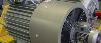
Squirrel cage. Design of an asynchronous squirrel-cage electric motor.
Asynchronous brushless motors are most widely used due to their comparative simplicity and reliability in operation. Commutator motors have limited use in installations where it is necessary to regulate the speed of driven mechanisms over a wide range. However, they are relatively heavy, expensive, have worse performance characteristics compared to brushless motors, and most importantly, are less reliable in operation due to difficult current switching conditions. Asynchronous brushless machines have two main designs: with a short-circuited rotor winding and with a phase rotor winding - with slip rings. From the point of view of the electromagnetic processes occurring in an asynchronous motor, two most important parts can be distinguished: a stationary stator, which ensures the creation of a rotating magnetic field, and a rotating rotor, in which an electromagnetic torque is created, transmitted to the driven mechanism. The stator cores are made from sheets of electrical steel 0.5 mm thick and less often 0.35 mm thick, insulated from each other with a varnish coating (in the rotor cores of low-power engines, the insulation is a layer of scale on the surface of the sheet). Special grooves are made in the stator and rotor cores in which the corresponding windings are placed.
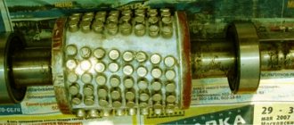
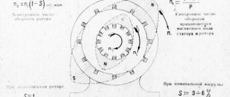
Rice. 1. Cast aluminum squirrel cage rotor of a squirrel-cage induction motor (with a short-circuit ring and ventilation blades) One of the most common rotor windings is a squirrel cage, the so-called squirrel cage (outwardly it resembles a squirrel wheel - Fig. 1). The working wires of this winding (rods) are laid uninsulated in the grooves of the rotor, which ensures good use of the groove area and good heat transfer from the rods to the active steel. Squirrel-cage asynchronous motors have the following modifications according to the rotor design: with a single squirrel cage; deep groove; with a double squirrel cage, or two-cage. The structural difference between these modifications determines the difference in the characteristics of these machines, primarily the launch ones. Rice. 2. Grooves and rods of the rotor windings. a - single squirrel cage; b—deep groove; c - double squirrel cage. Asynchronous motors with a single squirrel cage on the rotor have grooves stamped into oval or round sheet steel (Fig. 2a). From above these grooves are covered with a bridge 0.4-0.5 mm thick and filled with aluminum. At both ends of the rotor there are aluminum rings that close all the rods cast in the grooves. Such a cast single squirrel cage is often additionally equipped with special aluminum wings on both sides of the rotor (see Fig. 1). These wings are installed to increase heat dissipation from the squirrel-cage rotor and for better ventilation inside the asynchronous machine. In asynchronous electric motors with a deep-slotted rotor (Fig. 2, b), the squirrel cage is usually made of copper rods of rectangular cross-section. Short-circuit rings at the ends of the rotor, as a rule, are also made of copper, in which slots are milled in accordance with the dimensions of the rectangular rods. The rods and rings are soldered to each other with refractory solders. The two-cage rotor (Fig. 1,c) is made with two squirrel cages. The outer winding is made of brass or special bronze, which ensures its relatively high active resistance and relatively low inductive resistance. This winding performs the starting function in an asynchronous motor. The other rotor winding, the internal winding, is made of copper with minimal active resistance. It performs the functions of the main working winding of the motor. Both windings have round grooves, but the inner winding in some cases is rectangular or oval. The shorting end rings for both windings are usually made of copper. There are other modifications of the rotor slots (bottle profile, trapezoidal profile), however, those described above are most typical for asynchronous motors. In an asynchronous motor, the rotation speed of the rotor, entrained by the magnetic field of the stator, is less than the rotation speed of the field itself. In fact, if these frequencies were equal, the movement of the field relative to the rotor would cease, since the electromotive force would cease to be induced in the rotor, creating currents in its windings. In this case, the interaction of the rotor with the rotating field would cease and the cause of rotation of the rotor would be eliminated. In this case, the rotor would inevitably begin to slip, i.e., its rotation frequency would become less than the rotation frequency of the magnetic field, which corresponds to the actual position in an asynchronous motor. Due to the difference in the rotation frequencies of the field and the rotor, the machines under consideration are called asynchronous. When studying the phenomena occurring in the rotor of an asynchronous motor when it is braked (i.e., with a stationary rotor), we can conclude that the machine in this mode, by its physical nature, is a transformer. The primary winding of the transformer is the stator, and the secondary winding is the rotor winding. In general, an asynchronous motor differs from a transformer mainly in its design. In an asynchronous machine, the secondary winding is separated from the primary winding by an air gap, which is not the case in general industrial transformers. In addition, the secondary winding of the motor rotates relative to the primary. As noted above, the rotational speed n at which the rotor rotates must differ from the rotational frequency of the magnetic field n1. Depending on the ratio of these frequencies, there are three modes of operation of an asynchronous machine: motor, generator, brake. When an asynchronous machine operates in motor mode, the rotor speed changes within 0p1), then the asynchronous machine will switch to generator mode. In this case, the direction of rotation of the stator field relative to the rotor will change to the opposite compared to the operation of the machine in motor mode. The electromagnetic torque on the shaft, developed by an asynchronous machine, becomes braking in relation to the motor, which causes it to rotate. The mechanical energy transmitted by this motor to the asynchronous machine is converted into electrical energy and sent to the network to which its stator is connected. The operating mode of an asynchronous machine, when the rotor is driven against the direction of rotation of the electromagnetic field of the stator, is called the electromagnetic brake mode. ?
Design of an asynchronous motor with a squirrel-cage rotor
All electric motors contain two main parts that interact with each other. These parts are the stator and the rotor. The stator initiates the interaction, and the rotor responds with its rotation. All electric motors are classified based on one principle or another that ensures the interaction of the main parts. For example, in an engine, the stator, like the primary winding of a transformer, induces electromagnetic processes in the secondary winding - the rotor. This means it is an asynchronous electric motor.
Varieties of the simplest transformer engines
AC motors can be synchronous. The circuit turns out to be simpler, and the motor is cheaper. Although all induction motors contain a stator similar to a synchronous machine, the design of the rotor makes them significantly different. It does not need to be magnetized in one way or another, as is done in a synchronous engine. Despite the differences between the models of asynchronous machines, the design of their rotor is the equivalent of a short-circuited secondary winding.
The simplest option is a squirrel cage rotor. It can simply be cast from a ferromagnetic material and processed properly. Iron-based alloys conduct electrical current and interact with magnetic fields. The all-metal design has the following advantages:
- the easiest to manufacture and for this reason has the lowest cost;
- best withstands the forces generated during engine operation;
- accelerates well due to the effective interaction of magnetic fields.
Design
Every electric motor has two important working parts: the rotor and the stator. They are enclosed in a protective casing. To cool the winding conductors, a fan is installed on the rotor shaft. This is the general principle of the structure of all types of electric motors.
The designs of the stators of the electric motors under consideration are no different from the structure of these parts in other types of electric motors operating in alternating current networks. The stator cores, designed to operate at three-phase voltage, are arranged in a circle at an angle of 120º. Windings of insulated copper wire of a certain cross-section are installed on them, which are connected by a triangle or star. The design of the stator magnetic circuit is rigidly mounted on the walls of the cylindrical housing.
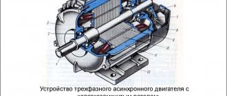
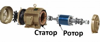
The structure of the electric motor is clear from Figure 1. Pay attention to the design of the windings without a core in a squirrel-cage rotor.
Rice. 1. Structure of an asynchronous motor with a short-circuit rotor
The rotor is designed a little differently. The design of its winding is very similar to a squirrel cage. It consists of aluminum rods, the ends of which are closed by short-circuiting rings. In high-power motors, you can see the use of copper rods as short-circuited rotor windings. This metal has low resistivity, but is more expensive than aluminum. In addition, copper melts faster, and this is not desirable, since eddy currents can greatly heat the core.
Structurally, the rods are located on top of the rotor cores, which consist of transformer steel. When manufacturing rotors, the cores are mounted on the shaft, and the winding conductors are pressed (poured) into the grooves of the magnetic core. In this case, there is no need to insulate the core grooves. Figure 2 shows a photo of a rotor with short-circuit windings.
Rice. 2. Rotor of an asynchronous motor with short-circuit windings
The magnetic core plates of such rotors do not require varnish insulation of surfaces. They are very simple to manufacture, which reduces the cost of asynchronous electric motors, the share of which is up to 90% of the total number of electric motors.
The rotor rotates asynchronously inside the stator. Minimum distances in the form of air gaps are established between these parts. The optimal gap is between 0.5 mm and 2 mm.
Depending on the number of phases used, asynchronous electric motors can be divided into three types:
They differ in the number and location of stator windings. Models with three-phase windings are characterized by high operating stability at rated load. They have better starting characteristics. Often such electric motors use a simple starting circuit.
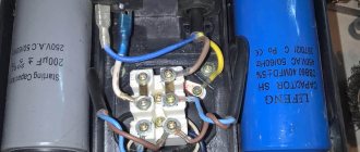
Two-phase motors have two stator windings arranged perpendicularly, each receiving alternating current. They are often used in single-phase networks - one winding is connected directly to the phase, and a phase-shifting capacitor is used to power the second. Without this part, the rotation of the asynchronous electric motor shaft will not begin on its own. Due to the fact that the capacitor is an integral part of a two-phase electric motor, such motors are also called capacitor motors.
In the design of a single-phase electric motor, only one working winding is used. To start rotor rotation, a starting inductor is used, which is briefly connected to the network through a capacitor or short-circuited. These low-power motors are used as electric drives for some household appliances.
Design features
The main elements of an electric motor for any purpose are the stator and rotor. To protect against contact with surrounding objects, the winding system is closed in a durable casing. An addition in the form of a cooling fan mounted on the rotor shaft allows you to prevent overheating of the windings.
The stator of an asynchronous three-phase motor with a squirrel-cage rotor has a structure standard for electric motors. The design, designed to work with three-phase windings, involves the arrangement of the cores at an angle of 120°. The windings are made of copper wire of suitable cross-section, insulated. The windings are connected in a star or triangle (it is described in separate articles). The stator magnetic circuit is rigidly fixed to the walls of the housing.
The rotor part has an appearance similar to a small cylindrical cage. Paired rings act as a short-circuiting element for rods made of aluminum. If we consider a high-power structure, the core parts of the structure can be made of copper. The reason for using this material is its low resistance. However, there are also disadvantages - copper for winding is more expensive than aluminum and melts faster when the core is heated by eddy currents.
The arrangement of the rods during assembly is carried out on top of the cores made of special transformer steel. Installation is carried out on the shaft of the unit, the winding wire is pressed into special grooves of the magnetic circuit. The ease of manufacture is enhanced by the fact that in this design the magnetic conductor plates do not require insulation. This is one of the main factors that made the squirrel-cage asynchronous unit the most popular (its share in the total mass of electric motors reaches 90%).
Low-power analogues
Research on three-phase asynchronous motors suggests that this type is the most efficient in most situations. However, there are also single- and two-phase motors. A single-phase operating circuit implies the presence of only one winding on the stator, which receives power in the form of alternating voltage. In this case, the stator is equipped with a special starting winding, which receives a starting pulse through a capacitor or using inductance. Some models produce a momentary short circuit. This is done to create a phase shift; without it, the rotor will not start rotating due to the pulsation of the stator magnetic field.
Single-phase electric motors, the asynchronous systems of which use magnetic fields, are also equipped with rotors in the form of a cylinder with grooves filled with aluminum and cooling blades monolithically connected to it. This rotor design is called squirrel-cage; Sometimes you can find the designation “squirrel cage”. The scope of application of single-phase motors is low-power household equipment.
If only a single-phase alternating power supply network is available, it would be rational to use a two-phase motor. These units also have a stator with two perpendicular windings. One winding is directly connected to the power supply network, and a capacitor is installed in front of the second winding, providing a phase shift. This circuit allows you to set the rotation of the magnetic field and ultimately start the electric motor.
Two-phase motors have more capabilities than single-phase motors. Therefore, their field of operation is household and industrial equipment with low and medium loads. Another name for two-phase units is capacitor; this is due to the presence of a capacitor, the main component that allows the rotor to move.
What kind of breakdowns happen with asynchronous electric motors?
Despite the fact that asynchronous electric motors are simple mechanisms, if they are not operated correctly, when there are difficult weather conditions around and there are deviations in the parameters of the power supply networks from the nominal ones, then they fail. In general, all breakdowns of electric motors with phase and short-circuited parts are divided into 2 groups: electrical and mechanical.
Mechanical failure
This area includes defects in motor housings and fan impellers. The shaft may also become deformed, the bearings may wear out, and the fastenings of the stator windings may become loose. The most common mechanical damage involves problems with bearings. When they wear out, noise increases and vibrations occur when the engine operates, then the engine overheats.
Electrical breakdowns
This area includes interturn closures. Also, when the winding breaks, the insulation on the body breaks through, the insulating resistance decreases, the connections on the contacts, the insulation of the magnetic circuit are broken, the brushes wear out or the slip rings are damaged.
To find out the condition of the stator winding, you will have to use a multimeter. It will also help to identify the supply voltage and whether all three phases are present. But they will not be able to identify the insulation resistance of the winding. You'll have to use a megohmmeter. It is he who will measure the resistance when it is applied to test objects with increased voltage. If the resistance is less than the required 0.5 Mohm, then the motor is dried. But before this, the rotor of a four-pole asynchronous motor is removed from it and a powerful incandescent lamp is inserted in its place. When drying is completed, measurements are taken again and the resistance is calculated. In some cases it helps.
The most common breakdowns associated with asynchronous electric motors:
- misaligned shafts;
- motor operation in 2 phases;
- interturn short circuits;
- imbalance in electric motor parts;
- the fastenings of the squirrel cage rods break or become loose;
- the stator is overloaded or overheats;
- bearings are damaged;
- uneven air gaps between stators and rotors.
In some cases, replacing the short-circuit bearing or eliminating engine overload will help. Adding oil or cleaning, drying, checking the voltage on the supply wires, assigning and eliminating short circuits also helps. But before all manipulations, it is advisable to remove the protective covers. In extreme cases, you will have to completely change the entire engine.
Rules for repairing a rotor with a short-circuited winding
In these parts, the squirrel cage is most often damaged, as a result the rods weaken in the grooves and the contact is broken in the place where the rods are soldered to the short-circuited ring. As a result, a crack forms and the rod breaks. Due to the weakening of the fastenings of the rods in the grooves, its vibration increases. The result will be deformation, and at the end there will be a crack (just in those places where the rod comes out of the grooves and the short-circuited rings are connected). It is they that lead to breaks in the rods, and those ends that break damage the frontal part and its insulation. All this is typical for electric motors that have large starts.
If you identify defects in time, you can save the engine. But for this it will have to be disassembled. If the motor is working, then some signs may indicate the presence of broken rods. For example, vibration increases because the fastenings become loose or the spacer wedges in the winding rods break.
What to do if the startup time has increased
There are units that have difficulty starting the motor and do not develop the rated frequency. If several rods break, it will not even move. The asymmetry of magnetic fluxes causes strong vibration and additional forces appear for the electric motor to work normally.
When a pair of rods break, all of the above signs do not appear so strongly and therefore it is very difficult to detect a possible defect that has arisen in the squirrel cage. You have to inspect the unit visually. And don’t forget about inspecting the short-circuited winding:
- what are the colors of the burns on the short-circuited rings in the places where they are connected to the rod;
- wavy bends of segments that may appear due to unevenly elongated rods;
- burnt bolts connecting some of the launch cage segments;
- in which direction the ends of the rod are bent in the direction of the rotating unit - they arise when twisted into rings.
Each of the above defects can appear in equipment that has high peripheral speeds and a massive short-circuit ring.
You can find deflections that protrude from the end of the active steel rod. These defects are present in many squirrel cell rods. It happens in both synchronous and asynchronous motors. Other faults include a moving squirrel cage along its axis.
If the short-circuited cage does not break during operation, then these damages will not manifest themselves in any way and can only be identified after a careful inspection of the short-circuited windings during preventive repairs. You should look very carefully for cracks at the end of the rod that protrudes. It is better to use a chemical, electromagnetic or optical method to help.
How to remove damaged rods from a groove
It all depends on the design of the rod. If we are talking about bottle profile rods, which sit tightly in the grooves due to the existing caulking along the entire length of the unit, then they need to be removed by drilling, using drills with extended shanks or by first cutting a longitudinal slot two to three millimeters wide in the rods. This operation is performed with vulcanite stones, which were originally designed to cut pipes.
The devices are installed on carriages moved along guides made from angles and attached with a bracket to the shaft cages. Because of this cut slot, the fastening of the rod in the grooves will loosen and it may come out by about 5-8 cm. You need to grab it with a clamp - it will help to completely remove the rod from its groove. The short-circuited winding can be partially repaired not only directly in the workshop itself, but also at the place where the electric motor will be installed. But only in the case where this does not require resorting to machining of rods and short-circuit rings.
How to solder copper rods
If cracks are found on those parts of the rod that protrude from the active parts of the steel, then measures will have to be taken to eliminate them. When the crack is shallow and no more than ¼ of the rod itself, then it can be welded, but before that, cut out a gap in the deepening area that is larger than the size of the crack.
When it comes to deep cracks, the rod is simply cut and the section that is soldered to the short-circuited ring is drilled out. Through the hole that formed in the ring, you need to drill another hole in the end with a diameter of no more than half the diameter of the rod itself. In this place you need to install and solder a copper insert. Before soldering, you need to degrease and etch the end rings. This can be done using a clean rag, previously soaked in washing liquid. Etch for half a minute with a solution of nitric acid at a temperature of twenty degrees. And the etched area should then be rinsed under hot water. Then wipe dry and dry.
Winding repair
Definition and a little history
The author of the asynchronous motor is considered to be Mikhail Osipovich Dolivo-Dobrovolsky, who in 1889 received a patent for a motor with a “Squirrel Cage” type rotor, and in 1890 for a motor with a wound rotor, which are still used today without any special changes in design. And the first research and developments in this direction were carried out in 1888 by Galileo Ferraris and Nikola Tesla independently of each other.
The main difference between Dolivo-Dobrovolsky’s development and Tesla’s development was the use of a three-phase rather than two-phase stator design. The demonstration of the first engines took place at the International Electrotechnical Exhibition in Frankfurt am Main in September 1891. Three three-phase asynchronous electric motors were presented there, the most powerful of which was 1.5 kW. The design of these machines turned out to be so successful that it has not undergone significant changes to this day.
The definition of an asynchronous machine is as follows:
Squirrel wheel
Squirrel wheel
- a toy for domestic animals, usually small rodents (squirrels, mice, hamsters, chipmunks, etc.), which is a wheel within which the animal moves. Can also be used as a temporary cage for transferring an animal.
The design itself is a rotating wheel with a fixed axis of rotation and assumes that the animal can run in it for quite a long time (until it gets tired), but does not run away anywhere. Hence also the expression “Spinning (spinning) like a squirrel in a wheel
" The outline of the rotating wheel can be either lattice or solid with small protrusions. The distance between the rods (protrusions) is selected taking into account the anatomical features of a particular animal species.
It is an effective exercise machine for maintaining the physical tone of small pets.
There are also similar attractions for children and adults. In this case, both in a stationary version (the axis of rotation is fixed) and in a moving version (the axis of rotation is not fixed).
"Squirrel wheel" in electrical engineering
“Squirrel wheel” is a method of connecting electrical conductors in the rotor of an AC induction motor. Invented in 1889 by M. O. Dolivo-Dobrovolsky (German patent No. 51083 dated March 8, 1889 under the name “Anker für Wechselstrommotoren”). Outwardly it looks like a toy in which pets run.
see also
- A walking ball is a similar toy for small pets.
- A treadmill is a sports machine with a similar operating principle - an endless track that allows the runner to remain in place relative to the room.
| This is a draft article on zoology. You can help the project by adding to it. |
Write a review about the article “Squirrel Wheel”
Connection
The stator windings of a three-phase ADKR can be connected in a “delta” or “star” circuit. In this case, the sprocket requires a higher voltage than the triangle.
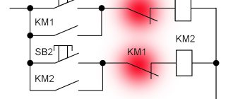
Please note that an electric motor connected in different ways to the same network consumes different power. Therefore, you cannot connect an electric motor designed for a star circuit according to the delta principle. But in order to reduce starting currents, you can switch the star-delta contacts during the start-up, but then the starting torque will also decrease.
The connection diagrams are clear from Figure 4.
Rice. 4. Connection diagrams
To connect a three-phase electric motor to a single-phase current, phase-shifting elements are used: capacitors, resistors. For examples of such connections, see Figure 5. You can use either a star or a triangle.
Rice. 5. Examples of connection diagrams for a single-phase network
In order to control the operation of the motor, additional devices are connected to the stator electrical circuit.