The evolution of network voltage - where it all began
The level of standard voltages has constantly changed over the past 100 years for domestic household networks, depending on the degree of technological development. Thus, at the dawn of the electrification of the countries of the Soviet camp, a nominal value of 127 V was set for consumers of electrical energy. This system of nominal parameters came into use thanks to the developments of Dolivo-Dobrovolsky, who proposed three-phase generation instead of the outdated two-phase. It should be noted that back in the late 30s of the last century, the voltage standard of 127 V already poorly corresponded to the increased production needs, it was then that the first attempts to replace it arose, but with the outbreak of World War II, these plans were never realized.
But already in the 60s, large-scale work began to bring the rated voltage to the new standard 220/380 V instead of three-phase alternating 127/220 V. European networks, by that time, had already made a massive transition to new ratings in order to avoid unreasonably costly replacement of wires with larger section. In an attempt to remain as efficient as possible, the Soviet countries also began a transition that was planned to be completed within the next five years. There was construction of new power plants, replacement of transformers and power units, but the process of transition to standards of 220 V phase voltage for household consumers dragged on until the 80s.
Socket rating
In 1992, GOST 29322-92 (IEC 38-83) introduced new voltage standards: 230 V phase instead of 220 V and 400 V linear instead of the usual 380 V.
This step was pursued by the desire to bring our own energy system on par with foreign ones for:
- convenience of working with immediate neighbors;
- opportunities for unhindered access to world markets;
- simplifying the transit procedure.
But, due to the imperfection of the entire domestic power supply system and the lack of funds for full-scale reconstruction, these voltage standards have not been established to this day.
STATE STANDARD OF THE USSR UNION
POWER SUPPLY SYSTEMS, NETWORKS, SOURCES, CONVERTERS AND RECEIVERS OF ELECTRIC ENERGY
RATED VOLTAGES OVER 1000 V
GOST 721-77
(ST SEV 779-77)
IPC PUBLISHING HOUSE OF STANDARDS
Moscow
STATE STANDARD OF THE USSR UNION
| POWER SUPPLY SYSTEMS, NETWORKS, SOURCES, CONVERTERS AND RECEIVERS OF ELECTRIC ENERGY Rated voltages over 1000 V Power supply system, networks, sources, converters and receivers of electric energy. Rated voltages above 1000 V | GOST 721-77 (ST SEV 779-77) |
Date of introduction 07/01/78
This standard applies to general-purpose electrical networks of alternating voltage with a frequency of 50 Hz and the sources and receivers of electrical energy connected to them.
The standard also applies to electrical equipment connected to these networks:
complete devices and substations, switching devices, current and voltage transformers, reactors, coupling capacitors, etc., for which the same rated voltages are standardized as those indicated for sources or receivers of electrical energy, and the classification of this electrical equipment by rated voltage as sources or receivers is determined in the regulatory and technical documentation for the relevant electrical equipment, approved in the prescribed manner.
The rated alternating voltages established in this standard are recommended at other frequencies specified in GOST 6697.
The standard does not apply:
a) for electrical networks and sources and receivers of electrical energy connected to them, for which Gosstandart has approved standards that provide for rated voltages that differ from those established in this standard, for example, for electrified (rail and trackless) transport powered by overhead contact lines;
b) on special electrical networks and sources and receivers of electrical energy connected to them, for example, for welding installations, industrial electric furnaces, on circuits closed inside electrical machines, apparatus and other electrical devices.
For special electrical networks and the electrical equipment used for them, whenever possible, the rated voltages specified in this standard should be adopted.
Special electrical networks and electrical equipment for them must have rated voltages specified in this standard on the side of connection to general-purpose electrical networks.
2. Nominal phase-to-phase voltages St. 1000 V three-phase electrical networks of sources and receivers of electrical energy, as well as their highest phase-to-phase operating voltages, long-term permissible under the operating conditions of electrical equipment insulation, must correspond to those indicated in the table.
For turbogenerators with a power of 100 MW and above, hydrogenerators with a power of 50 MW and above, synchronous compensators with a power of 160 Mvar and above and the primary windings of transformers and autotransformers directly connected to them, as well as corresponding electrical equipment, rated voltages of 138 are allowed; 15.75; 18.0; 20.0; 24.0 and 27.0 kV.
Moreover, for rated voltages 15.75; 20.0; 24.0 and 27.0 kV the highest operating voltages of electrical equipment should be equal to 17.5, respectively; 24.0; 26.5 and 30 kV; for rated voltages of 13.8 and 18.0 kV, the highest operating voltages of electrical equipment should be equal to 17.5 and 24.0 kV, respectively, with the highest long-term permissible voltages in electrical networks equal to 15.2 and 19.8 kV, respectively. Rated voltages St. 27 kV are allowed by agreement between the manufacturer and the consumer, while the highest long-term permissible voltage in the electrical network must be 10% higher than the rated voltage, and the highest operating voltage of electrical equipment must be no less than 10% higher than the rated voltage. For capsule hydrogen generators and the primary windings of transformers and autotransformers connected to them, as well as corresponding electrical equipment, a rated voltage of 3.15 kV is allowed with the highest operating voltage of electrical equipment being 3.6 kV.
kV
| Rated phase-to-phase voltages | Highest operating voltage of electrical equipment | |||||||||||||
| Networks and receivers | Generators and synchronous compensators | Transformers and autotransformers without on-load tap-changers | Transformers and autotransformers with on-load tap-changers | |||||||||||
| primary windings | secondary windings | primary windings | secondary windings | |||||||||||
| (6) | (6,3) | (6) | or | (6,3)* | (6,3) | or | (6,6) | (6) | or | (6,3)* | (6,3) | or | (6,6) | (7,2) |
| 10 | 10,5 | 10 | or | 10,5* | 10,5 | or | 11,0 | 10 | or | 10,5* | 10,5 | or | 11,0 | 12,0 |
| 20 | 21,0 | 20 | — | — | 22,0 | 20 | or | 21,0* | — | 22,0 | 24,0 | |||
| 35 | — | 35 | — | 38,5 | — | 35 | or | 36,75 | — | 38,5 | 40,5 | |||
| 110 | — | — | — | 121 | — | 110 | or | 115 | 115 | or | 121 | 126 | ||
| 220 | — | — | — | 242 | — | 220 | or | 230 | 230 | or | 242 | 252 | ||
| 330 | — | 330 | — | 347 | — | 330 | — | 330 | — | 363 | ||||
| 500 | — | 500 | — | 525 | — | 500 | — | 500 | — | 525 | ||||
| 750 | — | 750 | — | 787 | — | 750 | — | 750 | — | 787 | ||||
| 1150 | — | — | — | — | — | 1150 | — | — | — | 1200 | ||||
___________
* For transformers and autotransformers connected directly to the generator voltage buses of power plants or to generator terminals.
Electrical equipment must be manufactured for existing electrical networks with a rated voltage of 15 kV, as well as for electrical networks with a rated voltage of 400 kV.
The highest operating voltages for these networks are 17.5 and 420 kV, respectively.
1, 2. (Changed edition, Amendment No. 1, 2, 3).
3. If the transformer winding has several taps, the rated voltages indicated in the table refer to its main tap. The main branch is taken to be:
- with an odd number of branches - the middle branch;
- with an even number of branches - the branch with the closest high voltage to the average voltage of the regulation range.
Notes:
1. The rated voltages indicated in brackets are not recommended for newly designed networks. For existing and expanding electrical networks with rated voltages of 3 and 150 kV, electrical equipment must be manufactured.
2. The values of the highest operating voltages indicated in the table do not apply to short-term (lasting up to 20 minutes) voltage increases at a frequency of 50 Hz that are permissible under operating conditions.
3. The rated voltages of the windings of power transformers indicated in the table are set taking into account the highest long-term permissible voltage in electrical networks, equal to 3.5; 6.9; 11.5 and 23 kV, respectively, for networks with a rated voltage of 3; 6, 10 and 20 kV. Requirements for overexcitation of power transformers and voltage transformers should be established in the standards for these transformers, taking into account the above values of long-term permissible voltage in networks. For rated voltages from 35 to 1150 kV inclusive. the highest long-term permissible voltage in the networks is taken into account, which coincides with the highest operating voltage of electrical equipment indicated in the table.
4. For synchronous compensators, rated voltages of 6.6 are allowed; 11 and 22 kV.
5. (Deleted, Amendment No. 3).
6. For networks with a voltage of 1150 kV, the values of the rated voltages of the windings of transformers and autotransformers must be established after the approval of the standard for these transformers.
7. For electrical equipment used in the coal industry, phase-to-phase voltages of 1140 V for receivers and 1200 V for sources can additionally be used. At the same time, according to the requirements for technological maintenance and repair, equipment with phase-to-phase voltage up to 1200 V is equivalent to equipment up to 1000 V.
(Changed edition, Amendment No. 2,3).
INFORMATION DATA
1. DEVELOPED AND INTRODUCED by the Ministry of Energy and Electrification of the USSR
DEVELOPERS
L.G. Mamikonyants (topic leader), A.M. Bromberg, Y.S. Zhelezko
2. APPROVED AND ENTERED INTO EFFECT by Resolution of the State Committee of Standards of the Council of Ministers of the USSR dated May 27, 1977 No. 1376
3. Inspection period – 1994, inspection frequency – 5 years
4. The standard fully complies with the CMEA standard 779-77 and IEC Publication 38 (1975) as regards standard AC voltages above 1 kV
5. INSTEAD OF GOST 721-74 in terms of voltages. 1000 V
6. REFERENCE REGULATIVE AND TECHNICAL DOCUMENTS
| Designation of the referenced technical document | Item number |
| GOST 6697-83 | 1 |
7. Tested in 1982. By Decree of the State Standard of December 13, 1982 No. 4696, the validity period was removed
8. REISSUE (August 1997) with Amendments No. 1, 2, 3, approved in April 1979, December 1982, March 1989 (IUS 5-79, 3-83, 6-89)
Disagreements in GOSTs
How can it be that there are norms, new requirements are given in the standard, but practical implementation has not come even after almost thirty years. The reason for this was the constant increase in the power of household appliances, their number and growing consumption. Therefore, power supply organizations could not even achieve the permissible deviations of the previous standard rated voltage.
The first of the standards under consideration is GOST 32 1 44-2013, intended to determine the main parameters of the quality of electrical energy. As one of these indicators, the standard establishes acceptable ranges for potential differences.
Of course, it makes no sense to consider all the points and their calculation part, so we will discuss the most important points:
- according to clause 4.2.2, the rated voltage is considered to be 220 V between phase and zero, and 380 V for the linear norm.
- voltage dips, which, as a rule, are caused by the introduction of powerful consumers, the duration of the dip should not exceed 1 minute;
- in accordance with clause 4.3.3, pulse overvoltages, which can be caused by atmospheric discharges, range from 1 microsecond to several milliseconds;
- the asymmetry of the three-phase network according to clause 4.2.5 should be no more than 2 - 4% of the asymmetry coefficient in a ten-minute interval according to the weekly characteristic.
For comparison with previous standards, GOST 29322-2014 is in force, which refers to international standards and establishes the nominal characteristics of voltage series. It was developed in accordance with other standards - IEC 60038:2009 and repealed the 1992 standard. But in it, according to clause 3.1, the rating of household energy networks is set at 230 V and 400 V for electrical networks with alternating current with a frequency of 50 Hz. It is worth saying that for foreign networks with a frequency of 60 Hz there are some differences, but the permissible frequency deviation is only 2%, so these amendments are irrelevant for domestic consumers.
Preface
The goals, basic principles and procedure for carrying out work on interstate standardization are established by GOST 1.0-92 “Interstate standardization system. Basic provisions" and GOST 1.2-2009 "Interstate standardization system. Interstate standards, rules and recommendations for interstate standardization. Rules for development, adoption, application, updating and cancellation"
Standard information
- PREPARED by the Open Joint-Stock Company “All-Russian Scientific Research Institute of Certification” (JSC “VNIIS”);
- INTRODUCED by the Federal Agency for Technical Regulation and Metrology;
- ADOPTED by the Interstate Council for Standardization, Metrology and Certification (protocol dated September 30, 2014 N 70-P).
The following voted for the adoption of the standard:Short name of the country according to MK (ISO 3166) 004-97 Country code according to MK (ISO 3166) 004-97 Abbreviated name of the national standardization body Armenia A.M. Ministry of Economy of the Republic of Armenia Belarus BY State Standard of the Republic of Belarus Kazakhstan KZ Gosstandart of the Republic of Kazakhstan Kyrgyzstan KG Kyrgyzstandard Moldova M.D. Moldova-Standard Russia RU Rosstandart Ukraine U.A. Gospotrebstandart of Ukraine - By order of the Federal Agency for Technical Regulation and Metrology dated November 25, 2014 N 1745-st, the interstate standard GOST 29322-2014 was put into effect as a national standard of the Russian Federation on October 1, 2015;
- This standard is modified from the international standard IEC 60038:2009 IEC standard voltages.
At the same time, additional and amended provisions that take into account the needs of the national economy of the above states are highlighted in the text in italics, as well as a vertical line located in the margins of this text. The international standard was developed by the International Electrotechnical Commission (IEC). - INSTEAD GOST 29322-92
Information on changes to this standard is published in the annual information index “National Standards”, and the text of changes and amendments is published in the monthly information index “National Standards”. In case of revision (replacement) or cancellation of this standard, the corresponding notice will be published in the monthly information index “National Standards”. Relevant information, notifications and texts are also posted in the public information system - on the official website of the Federal Agency for Technical Regulation and Metrology on the Internet.
What is the network voltage
Since 2003, a standard voltage of 230V should have appeared in the sockets of our apartments and private houses. But for the past 17 years this transition has not been completed.
From September 30, 2014, instead of GOST 29322-92, GOST 29322-2014 (IEC 60038:2009) was adopted, establishing what the standard voltage should be in Russia. Now its value is 230 V (±10%) at a frequency of 50Hz (±0.2). But still quite often there is 220 V in the electrical network instead of the expected 230 V.
The rated parameters of AC power networks up to 1000 V are indicated in the table given in GOST 29322-2014.
In the first and second columns, the smaller values are the voltage between phase and neutral (phase), the larger values are between phases (linear). If one value is specified, it is the voltage between phases of a three-phase three-wire system.
The standard voltage of 230/400 V appeared as a result of the evolution of the 220/360 V and 240/415 V systems. Currently, the 220/360 system is no longer used in Europe and other countries, but 220/380 V and 240/415 V are still actively used.
The change in standards was caused by the need to bring electricity into full compliance with European parameters to facilitate the export and import of electricity and electrical devices.
Introduction
This standard specifies voltage ratings for a.c. and d.c. electrical systems, networks, circuits and equipment used in member countries of the International Electrotechnical Commission.
This standard fully complies with the IEC 60038:2009 standard in its construction, sequence of requirements, numbering of sections and subsections. Compared to IEC 60038:2009, this standard has been updated with updated references to international standards and definitions of terms.
The lowest usable voltage in Table A.1 of Annex A of this standard is specified for a maximum voltage drop between the user's electrical installation input and the electrical equipment, which is 4%. This maximum voltage drop in the electrical circuits of an electrical installation was specified in the previous standard IEC 60364-5-52:2001. In Table G.52.1 of the currently valid standard for electrical installations connected to public electrical networks IEC 60364-5-52:2009, different values for the maximum voltage drop are established:
- for electric lamps - 3%;
- for other electrical receivers - 5%.
Permissible voltage deviations in the network
Our network does not always have exactly 230 Volts.
Often, outdated network equipment, errors in network design, poor quality maintenance, deterioration of the networks themselves, and a large increase in electricity consumption lead to a significant deviation from existing standards.
The table (GOST 29322-2014), a fragment of which is presented below, normalizes the highest and lowest voltage in AC systems up to 1000 V.
According to GOST 29322-2014, in 2022 the network should have:
- 230 Volt;
- permissible deviations 207 - 253 V.
Where does the voltage come from?
To supply electricity to an outlet, it must be generated somehow. To generate electricity, technologies from the late 19th century are still mostly used - electromagnetic induction, which converts mechanical energy into electrical energy. In other words, generators. The difference between generators is only in how mechanical energy is supplied. Previously, these were bulky steam engines. Over time, hydraulic turbines for running water (hydroelectric power stations), internal combustion engines, and nuclear reactors were added.
The operating principle of the generator is based on magnetic induction. The rotational movement of the generator is converted into electric current. That is, we can say that a generator is the same electric motor, but of reverse action. If voltage is applied to the electric motor, it will begin to rotate. The generator works in reverse. The rotational movement of the generator shaft is converted into electric current. Therefore, in order to rotate the generator shaft, we will need some kind of external energy. It could be steam that spins the turbine, which in turn spins the generator shaft
Operating principle of thermal power plants
It will be interesting➡ Features of using pass-through switches
or it can be the force of the water flow, which, with the help of a hydraulic turbine, spins the generator shaft, and it, in turn, also generates electric current
Operating principle of hydroelectric power station
Well, or it could even be a windmill
Wind power plant
In short, the principle is the same everywhere.
By the way, a nuclear reactor is not capable of generating energy on its own. In fact, a nuclear power plant is the same primitive steam boiler, where the working fluid is ordinary steam. Yes, today there are other ways to generate electricity, such as the same solar cells, beta-galvanic and isotope nuclear batteries, “mythical” tokomaks. However, the above-mentioned “high-tech” has significant limitations - the prohibitive cost of materials, installation and setup, dimensions and low efficiency. Therefore, it is not worth seriously considering all this as a full-fledged high-power power plant (at least in the next couple of decades).
Varieties
There are two types: constant and variable. The first is in electrostatic types of circuits and those that have direct current. Variable occurs where there is sinusoidal energy. It is important that sinusoidal energy is divided into effective, instantaneous and average rectified. The unit of measurement for electric current voltage is volt.
It is also worth noting that the amount of energy between the phases is called the linear phase, and the indicator of the ground and phase current is called the phase current. A similar rule is used in all overhead lines. On the territory of the Russian Federation, the standard household electrical network is 380 volts, and the phase network is 220 volts.
Main varieties
Constant pressure
Constant is the difference between electrical potentials, at which the same value remains the same with polarity changes over a specific period. The main advantage of constant energy is the fact that there is no reactive power. This means that all the power that is generated by the generator is consumed by the load, excluding wire losses. Flows throughout the entire conductor cross-section.
As for the disadvantages, there is the difficulty of increasing with decreasing energy, that is, at the moment of converting it due to the design of the converters and the lack of powerful semiconductor switches. In addition, it is difficult to decouple high and low energy.
Note! Constant energy is used in electronic circuits, galvanic cells, batteries, electrolysis plants, welding tools, inverter converters and many other devices.
D.C
AC voltage
An alternating current is a current that changes in magnitude and direction periodically, but at the same time maintains its direction in an electrical circuit unchanged. It is often called sinusoidal. One direction in which energy moves is called positive, and the other is called negative. Therefore, the resulting quantity is called positive and negative. This exponent is an algebraic quantity. In answer to the question of what the unit of voltage is called, it should be noted that it is a volt. Its value is determined by direction. The maximum value is amplitude. It happens:
- two-phase;
Two-phase
- three-phase;
Three-phase
- multiphase.
Multiphase
It is actively used in industry, at a power station, at a transformer substation and is transmitted to every home using electrical transmission lines. Mostly three phases are used for connection. This type of electrification is common on many railways.
Note! It is worth noting that there are also some types of dual-system electric locomotives, which operate in many cases at a variable rate.
Alternating current
Excursion into history
So, the generator at our power plant converts mechanical energy into electrical energy. What's next? In what form and how exactly to transfer energy to the consumer? How to avoid colossal transmission losses?
Amazingly, such a situation actually existed! In the Russian Empire, until the beginning of the 20th century, there was complete confusion. A separate power plant was built next to each “large” consumer of electricity (a factory, the farmstead of a successful merchant, or a hotel for people of noble blood). There were many competing companies providing electrification services and, subsequently, their own electrical equipment tailored only for their network. Each electricity supplier set its own power grid parameters - voltage, frequency. There were even DC power grids! A person who bought, for example, light bulbs from the Lodygin and Co. Electric Lighting Partnership could only use them in the electrical network of the same company. If connected to the General Electric network, this light bulb would immediately fail - the network voltage of this company was significantly higher than necessary, not to mention other parameters.
Only in 1913 did imperial engineers decide to transmit electricity over long distances via overhead wire lines, eliminating the need to build power plants “at every outlet.” On the eve of the coming great war and the surge of patriotism, the authorities began to think about import substitution. Well, just like in our time, after the 2014 crisis). Many small Western firms (except German and French) were financially and legally suppressed; preferences and benefits were given only to domestic partnerships and enterprises. As a result, this led to monopoly in the electricity supplier market and, unwittingly, standardization of electrical network parameters.
Since Berlin and Paris were already electrified by a single power grid with 220 volt alternating voltage, domestic companies also adopted this standard. It was more convenient for people to use electrical appliances of a single type, without worrying that their newfangled electric vacuum cleaner would burn out at a new place of residence due to other parameters of the power grid. There was a complete displacement of many small firms - no one wanted to use their services and their devices, although they were forced to adapt to a single standard of the electrical network. Those same 220 volts AC.
How and why to evaluate the quality of voltage in the network?
Really, why? After all, all you have to do is press a button on the TV remote control or plug your iPhone charger into a power outlet and enjoy the benefits of electrification throughout the country!
But there are times when something goes wrong: the crocodile is not caught, the iPhone does not charge, the air conditioner produces a strained hum instead of coolness, and the TV shows no signs of life after a click.
Knowledgeable people have gathered here who understand that the values of the main parameters of the electrical network - voltage and frequency - can be found out primarily using a multimeter. But what to do if you need to see what is happening in the outlet during the day? But what if you need to track a voltage surge that is much shorter in time than the multimeter measurement interval? Moreover, it may be that the time of appearance of this artifact is unknown.
Usually, for any voltage problems, stabilizers are installed, but they do not always help. After all, the stabilizer eliminates the effect, but not the cause of the problem. And if there is an abrupt short-term change in voltage, then the stabilizer will not only not help, but will also worsen the situation.
And in order to understand what to do in this or that case - check the quality of the contacts at the input or install a stabilizer - you need a Power Quality Analyzer.
A power quality analyzer provides a complete picture of what is happening at the outlet.
It will be interesting➡ Connection diagrams for a three-phase meter. Installation of a three-phase meter
In my work I use the HIOKI 3197 electrical energy quality analyzer, photos of which will be given in the article.
Without a quality analyzer, it is often completely unclear what is happening in the network: what kind of interference, surge voltages and dips, power factor cos, and so on. You have to act at random, using your experience and experiments. And with the Japanese HIOKI from Nagano everything is clear. In order to get a complete picture of what is happening in the network, the device has clamps for measuring current and clamps for measuring voltage, as well as a clamp for connecting to the neutral. Total - 7 connection points.
Power Quality Analyzer
A real case when you can’t do without a quality analyzer. The controller in the production line periodically froze and generated errors. When everything was shoveled, but the cause was not found, a power quality analyzer came to the rescue. After a short observation of the 220 V voltage supplied to the controller, it turned out that the reason was poor contact inside the surge protector.
standard series of rated currents and voltages
The values of rated voltages at the terminals of electrically connected products, including electrical machines, are established by GOST 23366-78. The requirements of this GOST do not apply to circuits closed inside electrical machines; on circuits that are not characterized by fixed voltage values, for example, on the internal power circuits of electric drives with engine speed control, and on the circuits of devices for reactive power compensation, protection, control, measurements, on the electrodes of cells and batteries. GOST numbers (ST SEV)
GOST 12.1.009-76 GOST 721-77 (ST SEV 779-77)
GOST 1494-77 (ST SEV 3231-81) GOST 6697-83 (ST SEV 3687-82)
GOST 6962-75
GOST 8865-70 (ST SEV 782-77)
GOST 13109-67 GOST 15543-70
GOST 15963-79 GOST 17412-72 GOST 17516-72 GOST 18311-80 GOST 19348-82
GOST 19880-74 GOST 21128-83
GOST 22782.0-81 (ST SEV 3141-81) GOST 23216-78
GOST 23366-78 GOST 24682-81 GOST 24683-81
GOST 24754-81 (ST SEV 2310-80)
Standards for specific groups and types of products containing voltage ranges, including GOST 21128-83, GOST 721-77, which establish rated voltages for power supply systems, networks of sources, converters and receivers of electrical energy, are restrictive in relation to GOST 23366-78 and form a single set of standards with it.
GOST 23366-78 establishes the following nominal voltage values for products - consumers, sources and converters of electrical energy.
Rated voltages of consumers:
main range of DC and AC voltages, V: 0.6; 1.2; 2.4; 6; 9; 12; 27; 40; 60; 110; 220; 380; 660; 1140; 3000; 6000; 10000; 20000; 35000;
auxiliary AC voltage range, V:
1,5; 5; 15; 24; 80; 2000; 3500; 15000; 25000;
auxiliary DC voltage range, V:
0,25; 0,4; 1,5; 2; 3; 4; 5; 15; 20; 24; 48; 54; 80; 100; 150; 200; 250; 300; 400; 440; 600; 800; 1000; 1500; 2000; 2500; 4000; 5000; 8000; 12000; 25000; 30000; 40000.
Rated voltages of AC electrical energy sources and converters
, IN:
6, 12; 28,5; 42; 62; 115; 120; 208; 230; 400; 690; 1200; 3150; 6300; 10500; 13 800; 15 750; 18000; 20000; 24000; 27000; 38 500; 121000; 242000; 347000; 525000; 787000.
Rated voltages of DC electrical energy sources and converters, V:
6; 9; 12; 28,5; 48; 62; 115; 230; 460; 690; 1200; 3300; 6600.
For power sources of automotive and tractor equipment, the standard allows the use of rated voltages of 7V and 14V AC and 7V, 14V, 28V DC, as well as 36V AC with a frequency of 400 and 1000 Hz and 57V DC for aircraft power sources.
For short supply lines, the standard allows the rated voltage of sources and converters to be equal to the voltage of receivers.
The nominal values and permissible frequency deviations of power supply systems, sources, converters and electrical energy receivers directly connected to them, operating in steady state at fixed frequencies in the range from 0.1 to 10000 Hz, are established by GOST 6697-83. The specified GOST establishes the following main series of nominal frequencies of electrical energy sources, Hz:
0,1; 0,25; 0,5; 1,0; 2,5; 5,0; 10; 25; 50; 400; 1000; 10000.
For converters and receivers of electrical energy, nominal frequencies, Hz, are selected from the range 0.1; 0.25; 0.5; 1.0; 2.5; 5.0; 10; 12.5; 16|; 50; 400; 1000; 2000; 4000; 10000.
For a number of special drives and their power sources, in particular for centrifuges, separators, woodworking machines, power tools, gearless electric spindles, electrothermal equipment, the standard allows the use of additional frequencies, Hz, from the range 100, 150, 200, 250, 300, 500, 600 , 800, 1200, 1600, 2400, 8000.
For aviation equipment, aircraft and their maintenance equipment, a frequency of 6000 Hz is allowed.
Permissible frequency deviations, % of the nominal frequency, are selected from the range 0.0002; 0.0005; 0.001; 0.002; 0.005; 0.01; 0.02; 0.05; 0.1; 0.2; 0.5; 1.0; 1.5; 2.0; 2.5; 5.0; 10 and are established in standards for specific types of sources, converters or power supply systems.
For general purpose networks, the standards for the quality of electrical energy at its receivers are established by GOST 13109-67. The standard establishes the following indicators of power quality:
- when powered from single-phase electrical networks - frequency deviation, voltage deviation, range of frequency fluctuations, range of voltage changes, voltage non-sinusoidal coefficient;
- when powered from three-phase electrical networks - frequency deviation, voltage deviation, frequency fluctuation range, voltage change range, non-sinusoidality coefficient, voltage asymmetry and unbalance coefficients;
- when powered from DC electrical networks - voltage deviation, voltage variation range, voltage ripple coefficient.
INTERSTATE STANDARD “STANDARD VOLTAGES”
Standard voltages
ISS 29.020
OKP 01 1000
Date of introduction 01/01/93
INFORMATION DATA
1. PREPARED AND INTRODUCED by the Technical Committee for Standardization TC 117 “Energy Supply”
2. APPROVED AND ENTERED INTO EFFECT by State Standard Resolution No. 265 dated March 26, 1992
3. This standard has been prepared by direct application of the international standard IEC 38-83 “Standard voltages recommended by the IEC” with additional requirements reflecting the needs of the national economy
4. INTRODUCED FOR THE FIRST TIME
5. REFERENCE REGULATIVE AND TECHNICAL DOCUMENTS
| Designation of the referenced technical document | In which place |
| GOST 721-77 | Introductory part |
| GOST 6962-75 | » |
| GOST 21128-83 | » |
| GOST 23366-78 | » |
6. REPUBLICATION. May 2004
This standard applies to:
— power transmission systems, distribution networks and power supply systems for AC consumers, which use standard frequencies of 50 or 60 Hz at a rated voltage exceeding 100 V, as well as equipment operating in these systems;
— AC and DC traction networks;
- direct current equipment with a rated voltage below 750 V and alternating current equipment with a rated voltage below 120 V and a frequency (usually, but not only) 50 or 60 Hz. Such equipment includes primary or secondary batteries, other AC or DC power sources, electrical equipment (including industrial installations and telecommunications), various electrical appliances and devices.
The standard does not apply to the voltages of measuring circuits, signal transmission systems, as well as to the voltages of individual components and elements included in electrical equipment.
The a.c. voltages given in this standard are effective values.
This standard is used in conjunction with GOST 721, GOST 21128, GOST 23366 and GOST 6962.
The terms used in the standard and their explanations are given in the appendix.
Requirements that reflect the needs of the national economy are highlighted in bold.
1. STANDARD VOLTAGES OF AC NETWORKS AND EQUIPMENT
CURRENT IN THE RANGE FROM 100 TO 1000 V INCLUSIVE
Standard voltages in the specified range are given in table. 1. They refer to three-phase four-wire and single-phase three-wire networks, including single-phase branches from them.
Table 1
| Rated voltage, V | |
| Three-phase three-wire or four-wire networks | Single-phase three-wire networks |
| — | 120/240 |
| 230/400* | — |
| 277/480** | — |
| 400/690* | — |
| — |
_____________
* The rated voltages of existing 220/380 and 240/415 V networks must be brought to the recommended value of 230/400 V. Until 2003, as a first step, electricity supply organizations in countries with a 220/380 V network must bring the voltages to value 230/400 V (%).
Electricity supply organizations in countries with a 240/415 V network must also adjust this voltage to 230/400 V (%). After 2003, a range of 230/400 V ± 10% must be achieved. The issue of lowering the limits will then be considered. All these requirements also apply to voltage 380/660 V. It must be reduced to the recommended value of 400/690 V.
**Do not use in conjunction with 230/400 and 400/690 V.
In table 1 for three-phase three-wire or four-wire networks, the numerator corresponds to the voltage between phase and zero, the denominator corresponds to the voltage between phases. If one value is specified, it corresponds to the phase-to-phase voltage of a three-wire network.
For single-phase three-wire networks, the numerator corresponds to the voltage between phase and zero, the denominator to the voltage between lines.
Voltages greater than 230/400 V are used primarily in heavy industry and large commercial buildings.
Under normal network operating conditions, it is recommended to maintain the voltage at the consumer power point with a deviation from the nominal value of no more than ±10%.
2. STANDARD VOLTAGES OF POWER SUPPLY SYSTEMS
ELECTRIFIED TRANSPORT POWERED BY CONTACT
DC AND ALTERNATING CURRENT NETWORKS
Standard voltages are given in table. 2.
table 2
| Catenary voltage type | Voltage, V | Rated frequency in alternating current network, Hz | ||
| minimum | nominal | maximum | ||
| Permanent | (400)* | (600) | (720) | |
| 3600** | ||||
| Variable | (4750) | (6250) | (6900) | 50 or 60 |
| 50 or 60 |
_______________
*Values in parentheses are not preferred. These values are not recommended when creating new networks. In particular, on single-phase AC systems, the 6250 V nominal voltage should only be used when local conditions do not allow the 25000 V nominal voltage to be used.
The voltage values given in the table are adopted by the International Committee on Electric Traction Equipment and IEC Technical Committee 9 “Electric Traction Equipment”.
** In some European countries this voltage reaches 4000 V. Electrical equipment of vehicles involved in international traffic with these countries must withstand this maximum value for short periods of up to 5 minutes.
3. STANDARD VOLTAGES OF AC NETWORKS AND EQUIPMENT
CURRENT IN THE RANGE OVER 1 TO 35 kV INCLUSIVE
Standard voltages are given in table. 3.
Series 1 - voltages with a frequency of 50 Hz, series 2 - voltages with a frequency of 60 Hz. In one country, it is recommended to use only one of the voltage series.
The values indicated in the table correspond to phase-to-phase voltages.
Values in parentheses are not preferred. These values are not recommended when creating new networks.
It is recommended that in the same country the ratio between two successive rated voltages should be at least two.
Table 3
| Episode 1 | Episode 2 | |||
| Highest voltage for equipment, kV | Rated network voltage, kV | Highest voltage for equipment, kV | Rated network voltage, kV | |
| 3,6* | 3,3* | 3* | 4,40* | 4,16* |
| 7,2* | 6,6* | 6* | — | — |
| — | — | |||
| — | — | — | 13,2** | 12,47** |
| — | — | — | 13,97** | 13,2** |
| — | — | — | 14,52* | 13,8* |
| (17,5) | — | (15) | — | — |
| — | — | |||
| — | — | — | 26,4** | 24,94** |
| 36*** | 35*** | — | — | — |
| — | — | — | 36,5** | 34,5** |
| 40,5*** | — | 35*** | — | — |
* This voltage should not be used in general purpose electrical networks.
** These voltages usually correspond to four-wire networks, the rest - to three-wire networks.
*** Issues of unification of these values are considered.
In a series 1 network, the highest and lowest voltages should not differ by more than ±10% from the rated network voltage.
In a series 2 network, the maximum voltage should not differ by more than plus 5%, and the minimum by more than minus 10% from the rated network voltage.
4. STANDARD VOLTAGES OF AC NETWORKS AND EQUIPMENT
CURRENT IN THE RANGE OVER 35 TO 230 kV INCLUSIVE
Standard voltages are shown in table. 4. In one country, it is recommended to use only one of those indicated in the table. 4 series and only one voltage from the following groups:
— group 1 — 123 ... 145 kV;
- group 2 - 245, 300 (see section 5), 363 kV (see section 5).
Values in parentheses are not preferred. These values are not recommended when creating new networks. The values given in table. 4, correspond to phase-to-phase voltage.
Table 4
In kilovolts
| Highest voltage for equipment | Rated mains voltage | |
| Episode 1 | Episode 2 | |
| (52) | (45) | — |
| 72,5 | ||
| (170) | (150) | — |
5. STANDARD VOLTAGES OF THREE-PHASE AC NETWORKS
WITH THE HIGHEST EQUIPMENT VOLTAGE EXCEEDING 245 kV
The highest operating voltage of the equipment is selected from the following range: (300), (363), 420, 525*, 765**, 1200*** kV.
_________________
*A voltage of 550 kV is also used.
** Voltages between 765 and 800 kV may be used, provided that the test values for the equipment are the same as those specified by IEC for 765 kV.
*** An intermediate value between 765 and 1200 kV, respectively different from these two values, will be included additionally if such a voltage is required in any area of the world. In this case, in the geographical area where this intermediate value is adopted, voltages of 765 and 1200 kV should not be used.
The series values correspond to the phase-to-phase voltage.
Values in parentheses are not preferred. These values are not recommended when creating new networks.
In the same geographic area, it is recommended to use only one maximum voltage value for equipment in each of the following groups:
— group 2 — 245 (see Table 4), 300, 363 kV;
— group 3 — 363, 420 kV;
- group 4 - 420, 525 kV.
Note. The terms "region of the world" and "geographical area" can refer to a single country, a group of countries, or part of a large country where the same voltage level is selected.
6. STANDARD VOLTAGES FOR EQUIPMENT WITH RATED
VOLTAGE LESS THAN 120 VAC AND LESS THAN 750 VAC
DIRECT CURRENT
Standard voltages are given in table. 5.
Table 5
| Nominal values, V | |||
| DC voltage | AC voltage | ||
| preferred | additional | preferred | additional |
| — | 2,4 | — | — |
| — | — | — | |
| — | — | — | |
| — | 4,5 | — | — |
| — | — | ||
| — | — | ||
| — | 7,5 | — | — |
| — | — | — | |
| — | — | ||
| — | — | ||
| — | — | ||
| — | — | — | |
| — | — | ||
| — | — | — | |
| — | — | — | |
| — | — | ||
| — | — | ||
| — | — | — | |
| — | — | — | |
| — | — | — | |
| — | — | ||
| — | — | — | |
| — | — | — | |
| — | — | — | |
| — | — | — | |
| — | — | — |
Notes: 1. Since the voltage of the primary and secondary batteries (batteries) is below 2.4 V and the choice of the type of element used for various applications depends on criteria other than voltage, these voltages are not listed in the table. The relevant IEC technical committees may specify element types and corresponding voltages for a particular application.
2. If there are technical and economic justifications in specific areas of application, it is possible to use other voltages in addition to those indicated in the table. The voltages used in the CIS are established by GOST 21128.
ANNEX 1
Information
TERMS AND EXPLANATIONS
| Term | Explanation |
| Rated voltage | The voltage to which the network or equipment is designed and to which its operating characteristics relate |
| Highest (lowest) network voltage | The highest (lowest) voltage value that can be observed in normal operation of the network at any point at any time. This term does not apply to voltage during transient processes (for example, during switching) and short-term increases (decreases) in voltage |
| Highest operating voltage of equipment | The highest voltage value at which the equipment can operate normally indefinitely. This voltage is set based on its effect on the insulation and the equipment characteristics that depend on it. The highest voltage for equipment is the maximum value of the highest voltages of the networks in which this equipment can be used. |
| The highest voltage is indicated only for equipment connected to networks with a rated voltage above 1000 V. However, it should be borne in mind that for some rated voltages, even before this highest voltage is reached, it is no longer possible to carry out normal operation of the equipment from the point of view of such voltage-dependent characteristics, such as losses in capacitors, magnetizing current in transformers, etc. In these cases, the relevant standards must set limits under which normal operation of the devices can be ensured. | |
| It is clear that equipment intended for networks with a rated voltage not exceeding 1000 V, it is advisable to characterize only the rated voltage, both from the point of view of performance and insulation | |
| Consumer power point | The point in the distribution network of an electricity supply organization from which energy is supplied to the consumer |
| Consumer (electricity) | An enterprise, organization, institution, geographically isolated workshop, etc., connected to the electrical networks of the energy supply organization and using energy using electrical receivers |
Electrical voltage standards according to GOST
The regulatory document defines several indicators that allow characterizing the quality of electricity at connection points (input into consumer networks). We list the most significant parameters and give the permissible deviation ranges for each of them:
- For a steady-state voltage deviation no more than 5.0% of the nominal value (permissible norm) for a long time period and up to 10% for a short-term anomaly (maximum permissible norm). Please note that these indicators must be specified in the contract for the provision of services, and these standards must comply with current standards. For example, for household networks (220 V) it should be in the range of 198.0-220.0 V, and for three-phase (0.40 kV) - no less than 360.0 V and no more than 440 Volts.
- Voltage drops, such deviations are characterized by the amplitude, duration and frequency of intervals. The normally permissible amplitude range should not exceed 10.0% of the norm. Changes also include the flicker dose (flickering of light due to voltage changes, causing fatigue), this parameter is measured by a special device (flickometer). The permissible short-term dose is 1.38, long-term - 1.
Example of established voltage deviation and fluctuation - Throws and failures. The first include short-term increases in voltage amplitude exceeding 1.10 nominal. The second phenomenon means a decrease in amplitude by more than 0.9 from normal, followed by a return to normal parameters. Due to the nature of the processes, these deviations are not standardized. If this occurs frequently, it is recommended to install a voltage limiter (to protect against surges) and a UPS (for frequent dips).
- Overvoltage of the electrical network, this definition means an excess of the nominal value by more than 10% lasting more than 10 milliseconds.
Examples of overvoltage and sag (A), surges (B) - Voltage imbalance. The permissible deviation of the asymmetry coefficient from the norm is 2.0%, the maximum is 4.0%.
- Non-sinusoidal voltage. It is determined by calculating the distortion coefficient, after which the resulting value is compared with standard values.
Example of voltage sinusoidality violation - Frequency deviations. According to current requirements, the normally permissible deviation of this parameter is 0.20 Hz, the maximum permissible is 0.40 Hz.
Known voltage ratings
All long-distance power transmission lines operating today operate at rated voltages of 115–1200 kV three-phase current. Further increase in voltage is ineffective and leads to the appearance of abundant corona discharges, which tend to develop into an arc. The largest losses occur in the low-voltage part. For example, in France, annual losses are estimated at 325 GW hours, which is 2.5%, in the USA they reach 7.5%. This is explained by the difference in rated voltage - 220 V versus 110.
In 1980, the cost-effective length of the line was 7,000 km, but the actual ones are much shorter than this figure. At significant distances, capacitive and inductive reactance begin to play a role. Together they form a reactive impedance that prevents energy from being supplied to users. These are currents wandering here and there, representing a completely parasitic effect. This determines the line power factor, which is not too large.
Today it has been proven that it is more profitable to supply direct current over long distances that does not flow into inductive resistances - capacitive, formed by the wire and ground, and inductive. There is no concept of reactive power. The fact is proven that Nikola Tesla fought for alternating current mainly to cause damage to Edison.
Taking into account the savings, it is profitable to build converter stations at the ends of powerful lines to transfer currents. At the same time, losses due to radiation and leakage through the screen into the ground are reduced, and the level of corona discharge is reduced. Already today, cables for recharging submarine batteries are powered by direct current; it is impractical to transmit alternating current through them even at a distance of 30 km. Today's lines are 20 times longer and are successfully operated. For AC transmission, restrictions depend on distance:
- On small lines there are heat losses, designed not to destroy the wire insulation.
- At medium distances, the voltage drop is taken into account; you cannot take it too high.
- At long distances, reactive power factors come into force, determining the stability of the system.
Winding parameters
Rated operating voltage
Rated operating voltage (Nominal Voltage) is the voltage that must be applied to the winding for stable contact switching to occur. In most cases, a relay of the same rating has several winding modifications designed for different rated operating voltages.
Each modification differs in the number of turns.
In our example, these voltages are in the range 3, 4, 5, 6, 9, 12, 24, 36 and 48 Volts.
This means that the same type of relay can be used over a wide range of operating voltages.
Accordingly, windings designed for different voltages have different Coil Resistance, and different currents are required to control them.
From the datasheet we see that the higher the operating voltage of the winding, the greater its resistance, and the less current is needed to switch contacts.
It is interesting to note that at different operating voltages, the winding can consume the same power.
So, in our case, various modifications of the windings consume power of about 0.36 W when operating with voltages of 5 - 36 V and about 0.45 W when operating with a voltage of 48 V.
Operating voltage
It should be noted that the relay begins to operate at a voltage less than the rated voltage.
The voltage at which the relay operates is called Pick Up Voltage. At this voltage, the armature is attracted to the core in such a way that it switches the contacts.
Upon careful examination, you can see: if a voltage is applied to the winding less than the actuation voltage, the armature begins to move, but not enough to switch the contacts.
Often the response voltage is specified as a percentage of the rated voltage. So, in our example, the response voltage is 75% of the rated operating voltage.
Maximum operating voltage of the winding
The relay will operate stably even when the winding voltage is slightly higher than the rated voltage. In this case, some permissible overheating of the winding occurs. The maximum operating voltage (Maximum Continuous Voltage) is also indicated in the datasheet.
It may also be indicated as a percentage of the rated operating voltage. In our example, it is 150% of the rated operating voltage.
In other words, the relay can operate over a certain range of winding voltages. In our case, a relay, for example, with a 5 V winding can operate in the range from 3.75 to 7.5 V, and a relay with a 12 V winding can operate in the range from 9 to 18 V.
Release voltage
Drop Out Voltage is the winding voltage at which the armature, having previously been attracted, releases.
The release voltage may also be specified as a percentage of the rated operating voltage.
In our case, it is 10% of the nominal value.
Those. if, for example, the winding is designed for a rated voltage of 5 V, then the armature will release when the voltage on the winding drops to 0.5 V or less.
Sometimes reference data instead of actuation and release voltages indicate operation and release currents.
Please note: the trigger voltage and release voltage are very different!
In other words, it takes significantly less energy to keep the relay in the on state than to switch the relay from the off to on state.
To reduce the energy consumed from the power source, after the relay is activated, you can reduce the voltage on its winding to a value greater than the release voltage.
Now let's consider
Mains voltage parameters in Russia
Electricity producers generate alternating current at industrial frequency (50 Hz in Russia). In the vast majority of cases, three-phase current is transmitted along power lines, increased to high and ultra-high electrical voltage using transformer substations that are located next to power plants.
According to the interstate standard GOST 29322-2014 (IEC 60038:2009), the mains voltage should be 230 V ± 10% at a frequency of 50 ± 0.2 Hz [1] (phase-to-phase voltage 400, phase-neutral voltage 230 V, four-wire circuit " star"), note "a)" of the standard states: "However, 220/380 V and 240/415 V systems are still in use."
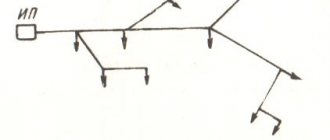
Four-wire connections (three phase wires and one neutral (neutral) wire) are supplied to residential buildings (rural streets).
power lines (overhead or cable power lines) with a phase-to-phase voltage of 400 Volts. Input machines and electricity consumption meters are usually three-phase. A phase wire, a neutral wire and, possibly, a protective grounding or grounding wire are supplied to a single-phase socket; the electrical voltage between the “phase” and “zero” is 230 Volts.
The rules for electrical installations (PUE-7) continue to include the value 220
but in fact, the voltage in the network is almost always higher than this value and reaches 230-240 V, varying from 190 to 250 V.
Peculiarities
Kharechko Yu.V. wrote about some features of using the rated voltage in his book [2].
“The electrical installation of a building is usually connected to a low-voltage electrical distribution network. The electrical installation of a building itself is a set of interconnected electrical equipment that performs specific functions. Therefore, by means of, among other things, the rated voltage, the characteristics of all electrical equipment used both in the electrical distribution network and in the electrical installation of the building are coordinated in order to ensure its normal functioning. »
[4]
The rated voltage values for electrical installations of buildings, as well as for other low-voltage and high-voltage electrical installations are established by the GOST 29322-2014 standard [2], which applies to:
- on alternating current electrical systems with a rated voltage of more than 100 V and a standard frequency of 50 Hz or 60 Hz, used for the transmission, distribution and consumption of electricity, and electrical equipment used in such systems;
- for AC and DC traction systems;
- for alternating current electrical equipment with a rated voltage of less than 120 V and a frequency (usually, but not exclusively) 50 or 60 Hz, direct current electrical equipment with a rated voltage of less than 750 V. Such equipment includes batteries (from cells or accumulators), other power sources AC or DC, electrical equipment (including industrial and communications) and household electrical appliances.
Currently in effect, since 2014.
But in Japan and on the American continent there is no less, and (in 39 countries) the standard voltage ranges from 100 to 127 volts.
Brazil stands out especially, in the northern regions of which the standard voltage is 127 volts, and in the rest - 220. In Japan, with a standard voltage of 110 volts, the network frequency can vary from 50 to 60 Hz.
The main solution for high-quality power supply is voltage stabilizers.
Unfortunately, emergency situations in the electrical networks of our homeland are quite frequent, and the consequences of voltage changes in our homes lead to the failure of expensive electrical appliances, the cost of which far exceeds the prices of voltage stabilizers and the prices of surge protection devices.
Modern technologies make it possible to ensure uninterrupted power supply with the specified parameters; one of such devices that can help is the HIDEN UPS, an even more advanced ECOVOLT UPS.
It will be interesting➡ Switch connection diagram
Amount of permissible voltage drop: PUE
According to the accepted rules for the design of electrical installations (PUE) back in the former USSR, a voltage drop is the difference in voltage levels at different points of the network. As a rule, these are the starting and ending points of the chain. In established standards, the law requires a distinction between the concepts of voltage deviation and voltage loss. If the first case, on a generally accepted scale, is considered using the example of an incandescent lamp, the deviation indicator of which is recognized as nominal and mandatory, then in the case of the loss considered on the station buses, this is recognized as a recommended indicator.
Normal voltage drop in the network:
- In so-called overhead lines – up to 8%;
- In cable power supply lines – up to 6%;
- In networks of 220 V - 380 V - in the region of 4-6%.
In this case, a drop in the emergency mode is considered to be a drop of up to 12% in the network - this is the established limit. A fall above the established norm promises the activation of the automatic protective system, which should be activated when the lower norm is reached for at least 30 seconds.
Also in some sources you can find voltage standards that exceed even the new indicators of 230 V and 400 V. Do not confuse examples of domestic use with a plant or factory, where the indicators naturally significantly exceed the domestic environment.
Conditions for normal operation of the electrical network
For stable operation of electrical receivers, the following rule of voltage equality must be observed: the rated voltage of electrical receivers must be equal to the rated voltage of the electrical network. Unom.ep = Unom.network. But in practice it is impossible to ensure such equality in which there will be no losses or damages.
The load of electrical receivers cannot be constant; it changes and deviates from the nominal value. The acceptable voltage deviation zone of the electrical receiver is ±5%.
In addition, the length of the power line implies a loss of voltage on the line, which means that the voltage at the receiver will be less than the voltage at the source. The difference in voltage will be the amount of loss. This is taken into account during the design and according to GOST, the voltages (nom.) generated by generators must be 5% greater than the required network voltage.
Deviation from rated voltage in the private sector
- Burnout of the neutral working conductor in a transformer substation
- Unbalanced load on power lines. Basically, there are 3 phases running along the street and power engineers try to evenly distribute the load among the phases. It often happens that this was done a long time ago and is not true. As a result, it turns out that one phase is overloaded and a voltage drop occurs, maybe 190 V or 180 V, but nevertheless this does not correspond to the norm.
- A neighbor's welding work may affect the voltage
- Lightning strike
Reference Information. If the house is located near a transformer substation, then the voltage may be close to 230 V or more, but this is within normal limits. Power engineers do this on purpose so that there is no strong voltage drop at the end of the line.
Remember! Switching and protective equipment (batch switch, circuit breaker, RCD) does not protect the electrical network from voltage surges.
Maximum voltage deviation in the electrical network
The current in the network is, for natural reasons, not constant and varies in certain parameters. Within the framework of the new 230 V/400 V standard, the nominal deviation is permissible within 5% and a maximum of no more than 10% should be observed in short-term intervals. Thus, such a theoretical deviation is allowed within 198 V and up to 242 V. This range can be considered relevant for most current apartments.
What affects network fluctuations in energy supply and voltage loss:
- One of the most common reasons is obsolescence of equipment, including meters, electrical panels, wiring cables, and so on;
- Significant errors are also observed in a poorly maintained network;
- Errors when planning and performing installation work in the house;
- Significant increase in energy consumption indicators exceeding the established standard.
As already noted, network fluctuations of +-5% are acceptable. So, for example, according to the supplied indicator of 220 volts, the permissible deviation in the network is equal to 209 V and the maximum excess is equal to 231 V.
Reduced (low voltage)
One of the electrical safety measures is the use of reduced voltage, taking into account the possible operation of equipment, devices, equipment. Thus, when operating all lighting equipment, a voltage of no higher than 127/220 V is used. And when working with portable power tools, as well as with hand-held portable lamps, the voltage is 36 or 42 V. In rooms with increased electrical safety, particularly dangerous and fire-explosion hazardous rooms, the voltage should not exceed 12 V.
Low voltage sources (12, 24, 36 and 42V) can be batteries, step-down transformers, frequency converters.
At the same time, the use of autotransformers and rheostats to reduce voltage is prohibited due to the connection of low- and high-voltage networks.
To reduce the danger of using step-down transformers, the secondary winding and the transformer housing are grounded or grounded.
Protective grounding, grounding
Safe work with electrical installations is ensured by grounding, grounding (in networks up to 1000V) and protective deflection.
Application area
According to GOST 12.1. 013-80 and GOST 12.1.030-80 “Electrical safety. Protective grounding, grounding", GOST 12.1.019-79 "Electrical safety. General requirements and nomenclature of types of protection,” grounding or zeroing should be performed:
- at a rated voltage of 380V and above alternating current, 440V and above direct current in electrical installation networks in any premises (including premises without increased danger);
- at a rated voltage of 36V and higher (according to GOST 12.1.013-80), 42V and higher (according to GOST 12.1.030-81) alternating current and 110V and higher direct current of electrical installations in high-risk premises and especially hazardous premises, in outdoor electrical installations;
- at any rated voltage of alternating and direct current electrical installations in all explosive conditions.
Parts of electrical installations that are subject to grounding or grounding:
— metal housings of electrical machines, transformers, apparatus, lamps, mobile electrical installations, portable electrical installations;
— frames, control panels, control rooms and cabinets, as well as removable or opening parts, if electrical equipment with a voltage higher than 42V AC or a voltage higher than 110V DC is installed on them;
— drives of electrical devices;
— secondary windings of instrument transformers;
-metal switchgear, metal small structures, metal couplings, metal sheaths and armor of control and power cables, metal sheaths of wires, electrical wiring pipes, etc.;
— reinforced concrete power transmission line supports.
Grounding of electrical equipment
According to its functional purpose, grounding is divided into three types - working, protective, lightning protection grounding.
Working grounding includes grounding of the neutrals of power transformers and generators, dead or through an arc suppression reactor.
Protective grounding is performed to ensure the safety, first of all, of people.
Lightning protection grounding serves to drain lightning current into the ground from protective arresters and lightning rods (rod or cable).
Protective grounding must fulfill its purpose throughout the year, while grounding and lightning protection - only during thunderstorms.
Purpose of protective grounding
. Protective grounding is intended to eliminate the risk of electric shock to people when they come into contact with metal parts of electrical equipment that are energized. The operating principle of protective grounding is to reduce touch and step voltages caused by a short circuit to the body of electrical equipment to a safe level. This is achieved by reducing the potential of the grounded equipment due to the low resistance of the ground electrode, as well as by equalizing the potentials of the base on which the person is located and the grounded equipment by raising the potential of the base to the level of the potential of the grounded equipment.
Protective grounding is a parallel connection to the electrical circuit of a grounding conductor with a significantly lower resistance Rз
(Fig. 3.3.4.6)
In networks with voltages up to 1000V, the resistance of the grounding device should be no more than 4 ohms, for voltages above 1000V - no more than 0.5 ohms.
With this inclusion in the electrical circuit, the current passing through the person will be equal to:
(3.4.21)
where, Rr
– human body resistance, Ohm
Itot —
total passing current through two ground electrodes (human body and ground electrode), Ohm;
Rtotal –
total resistance of grounding conductors, Ohm.
Fig. 3.4.6 Protective grounding: a – grounding diagram of the electrical equipment housing; b-equivalent electrical circuit
(3.4.22)
(3.4.23)
After substituting the values of Rtot
and
Itot
into formula / 3.4.21/ we get
(3.4.24)
Example.
Determine the magnitude of the damaging current when a person is single-phase connected to a three-phase network with an isolated neutral.
Let's assume that the resistance of the floor and shoes: Rп = Rоb = 0 Ru = 3000 Ohm
In the absence of grounding, the damage current:
A
If there is a protective ground:
A
As you can see, the damage current in the presence of a grounding device is significantly less than the holding one.
Protective grounding is used in electrical installations with voltages up to 1000V AC with an isolated neutral or with an isolated output of a single-phase current source, as well as electrical installations with voltages up to 1000V in DC networks with an isolated midpoint.
Grounding of installations consists of connecting their metal parts (normally not energized) to the ground with a ground electrode having low resistance to current flow.
The grounding device consists of grounding conductors, grounding bars and wires connecting the housings of electrical installations with grounding conductors.
Depending on the location of the grounding conductors relative to the grounded equipment, grounding devices are divided into remote and loop (Figure 3.4.7). External grounding switches
the grounding device is placed at some distance from the grounded equipment.
A loop grounding
device provides a higher degree of protection, since grounding conductors are located along the contour of all grounded equipment.
Fig. 3.4.7 Remote (a) and loop (b) grounding:
1-electrodes (grounding electrodes); 2 currents (buses); 3-electrical installations
In practice, grounding is carried out in the following order:
— a grounding device (artificial or natural) is selected;
— the grounding device is calculated;
-separate electrodes (grounding electrodes) are combined into one common grounding device;
— electrical installation housings are connected to a grounding device;
- documentation is drawn up for acceptance of the grounding device into operation.
When choosing a grounding device, natural grounding conductors are often used, which are pipelines laid in the ground and having good contact with the ground, steel pipes of electrical wires. During the construction of industrial buildings, metal building frames can be used as natural grounding conductors.
Pipelines for flammable liquids and explosive gases must not be used as grounding conductors. Metal and reinforced concrete structures, when used as grounding devices, must form a continuous electrical circuit through the metal (in reinforced concrete structures, embedded parts must be provided for connecting electrical and technological equipment).
When using reinforced concrete foundations as grounding conductors, the current spreading resistance of the grounding device is determined by the formula
(3.4.25.)
where Qe is the specific equivalent electrical resistance of the earth, Ohm • m;
s is the area limited by the perimeter of the building, m2.
Real voltage measurement examples
The simplest example of measuring voltage at home is a AA battery. In it you need to attach the black probe to the “–” terminal and the red one to the “+” terminal, set the switch position to 2 V DC voltage.
Example of measuring voltage on a battery
If the readings for a 1.5 V battery are in the range from 1.6 to 1.2 V, then such a power source is considered suitable for all equipment; if the values reduce to 1 - 0.7 V, pulsed devices will be started from the battery, for example, a watch. If the voltmeter shows 0.6 V or less, the discharge has reached a critical value.
When measuring the potential difference in a household network, you should touch the contacts of the socket with the probes. Since the insulated part of the probe has a restrictive ring behind which there is a long rod, you can safely reach into the outlet without the risk of touching live parts. Deviations from the nominal value by 10% are considered acceptable, that is, from 198 to 142 V.
You can also measure the potential difference at the output of a car battery or at another element of the electrical wiring circuit. To do this, the black probe of the multimeter is installed on the “–” terminal of the battery, and the red one on the “+” terminal.
If the battery is charged, then the voltmeter readings should be in the range from 12 to 14 V, but there are models with a large spread. This measurement allows you to diagnose various causes of problems.