Motion sensors (hereinafter referred to as motion sensors) gained worldwide recognition in the 90s of the last century. With their appearance on the radio engineering market, universal devices solved the important problem of saving energy and significantly extending the “life” of lighting devices. Today, household infrared radiation detectors are widely used to illuminate local areas, entrances, staircases and premises for various purposes. However, devices may break during operation. Many novice home craftsmen are interested in how possible it is to repair a motion sensor with their own hands.
Once again about sensor circuits
So, I will give the most popular motion sensor circuit again:
Motion sensor circuit 3
This diagram was sent by my regular reader Alexander from Korolev in December 2014, for which I thank him again. I will rely on this diagram throughout the text of the article, since it is the most typical. It should not be confusing that the circuit in our example will be scattered across two boards - low-current and power.
At the end of the article, a refinement of this scheme will be given.
Now I’m publishing photos of motion sensor boards sent by another reader of mine, Renat.
Low current motion sensor board
Motion sensor power board
Here is our correspondence with Renat:
- Renat: Hello! According to the diagram and description, I have the same sensor, I don’t know the exact model, they asked me to look at it, “it stopped working.” I settled on the power board. I checked all the elements, after the diode bridge + 24V comes out, the zener diode outputs + 8V, unsoldered the second part of the circuit (the board with the IR receiver, microcircuit, etc.). And now, I can’t understand why the relay activates when I apply voltage?
- Me: Is there an integrated stabilizer (KREN) type 7808, at the output 8V? You need to connect everything and then check it. When nothing is applied to the input of the key transistor, it can behave unpredictably. Check the power transistor, relay, adjustment elements, soldering. To go deeper - you need to understand the circuit - opamps, sensors, etc.
- Renat: Hello Alexander! An integral stabilizer is not worth it. I connected it, everything is still the same (the relay is activated, does not respond to the sensor, adjusting the sensor, time and “day”/”night” mode also does not change anything.
Renat did a great job with his own hands, and I will try to help him in this article.
Assembly diagrams
Microwave
To control open spaces and monitor the presence of objects in the desired area, there is a capacitive relay. The operating principle of this device is to measure the amount of radio wave absorption. Everyone has observed or been a participant in this effect when, approaching a working radio receiver, the frequency on which it operates gets lost and interference appears.
Let's talk about how to make a microwave-type motion sensor. The heart of this detector is a radio microwave generator and a special antenna.
This circuit diagram shows a simple way to make a microwave motion sensor. Transistor VT1 is a high-frequency generator and also a radio receiver. The detector diode rectifies the voltage by applying a bias to the base of transistor VT2. The windings of transformer T1 are tuned to different frequencies. In the initial state, when the antenna is not affected by external capacitance, the amplitudes of the signals are mutually compensated and there is no voltage on the detector VD1. When the frequency changes, their amplitudes are added and detected by a diode. Transistor VT2 begins to open. As a comparator for clear processing of the “on” and “off” states, thyristor VS1 is used, which controls a 12-volt power relay.
Below is an effective diagram of a presence relay using available components, which will help you assemble a motion detector with your own hands or simply be useful for getting acquainted with the device.
Thermal
Thermal IR (PIR) is the most common sensor device in the business sector. This is explained by cheap components, a simple assembly scheme, the absence of additional complex settings, and a wide temperature range of operation.
The finished device can be purchased at any electrical goods store. Often this sensor is equipped with lamps, alarm devices and other controllers. However, now we will tell you how to make a thermal motion sensor at home. A simple pattern to follow looks like this:
A special thermal sensor B1 and a photo element VD1 make up an automated lighting control complex. The device starts working only after dusk; the response threshold can be set with resistor R2. The sensor connects the load when a moving person enters the control zone. The time of the built-in timer for shutdown can be set using the R5 regulator.
Where to start repairs if the sensor does not work
These arguments and methods of mine apply not only to a specific motion sensor, but also to many electronic devices. For example, to a light sensor, the circuit of which is much simpler, but the principle is the same.
1. Check that the connection is correct. At this stage, you also need to find out why the motion sensor does not work and under what circumstances. Options (brainstorming):
- leap of light,
- turned off the electricity
- construction work,
- an electrician came to the neighbors,
- some kind of smell
- the children were spinning
- hit
- the dog chewed
- neighbors flooded
- there was wind yesterday
- sometimes it didn't work well
- etc.
At this stage, it is already possible to identify the direction in which to move further.
You need to check that the connection is correct, make sure that the sensor is receiving the correct power, and if there are indicators, they should be on. Some. Sometimes. Next, simulate a situation in which it should work.
2. Correct adjustments. The regulators may be installed incorrectly, and it is enough to adjust the sensor correctly. To do this, it is necessary to put the controls in positions in which it is most likely to turn on: Set the illumination level to a position at which the sensor will operate both day and night. Set sensitivity to maximum. Set operating time to minimum. In any case, it’s worth turning the controls and analyzing how the sensor behaves and whether it reacts at all.
Adjust your settings
If your motion sensor does not turn off the lights or is not working correctly, first take a closer look at the settings. There are three regulators on the body of the device: SENS, TIME and LUX.
- SENS — determines the level of sensitivity of the motion sensor to infrared radiation;
- TIME — adjusts the shutdown delay time;
- LUX - adjusts the light level: if the threshold is increased, the lighting will not turn on; if the light level is lower than the set level, the sensor will turn on the lighting devices.
These settings help prepare the sensor for specific conditions. Initially, they must be set either by the installer company or by the owner of the sensor.
When working with professional equipment, it is important to adhere to the recommended values. For example, the LUX regulator has these.
As practice shows, in passage areas it is approximately 75-200 lux, in work areas (offices and cubicles) - 600 lux, when working with heavy eye strain - 1000 lux. The average range of illumination levels in sensors is 2-2000 lux.
If you do not know the correct values, then it is better not to adjust these indicators yourself. Set the lowest value - the sensor will turn on at minimum illumination, set the maximum - the sensor will turn on constantly.
At the same time, from a technical point of view, the device will work correctly, that is, it will perform its functions based on the settings. On the practical side, its operation will not bring any benefit to the owner, so in case of such problems it is worth contacting a specialist who can adjust the device settings.
An incorrectly adjusted SENS parameter can also disrupt the operation of the motion sensor. If you set its value incorrectly, the sensitivity of the area where the motion sensor is present will decrease, and in certain cases, for example, with minimal movements, the device may simply not work.
Due to incorrect settings of the SENS, LUX and TIME parameters, the lighting may not go out. If the lamp does not turn off for a long time, in the absence of movement, then it is worth checking the turn-off delay time.
The TIME control may be set too high, preventing the output contact that controls the lights from opening. This indicator also has its average values: for passage areas - 5 minutes, for work areas - 15 minutes.
Opening the sensor
If after the first stage the sensor does not work, you need to get down to real work.
We open the sensor and look at the boards. The first thing you need to pay attention to is the integrity of the elements. In addition, the smell will tell a lot to a knowledgeable person. There should be no suspicious parts - darkened, cracked, swollen, loose.
The PCB tracks must be intact. Sometimes it happens that they crack or break near the ration points (nickels). And of course, if the track is burnt out, you need to restore it with a jumper and analyze the reason.
We carefully check the soldering. In case of the slightest suspicion, we shake the suspicious parts and solder these places. Often the input wires and wires between the boards are sealed off, as well as adjusting elements (variable resistors).
Test run
Connect power to the sensor. I recommend using an incandescent light bulb with a power of 25-60 W as a load to indicate the operation of the sensor. Otherwise, if you focus on the clicking of the relay, you may not hear or understand whether it is on or off. Now we check the relays and connections.
I highly recommend turning on any devices during repairs through the minimum possible circuit breaker. In this case - 1-2 Amperes. This is necessary to avoid troubles.
A better option is to connect through a transformer (with an output voltage of 220V) or a difavtomat, this will significantly reduce the risk of electric shock (we will work with open live parts!).
Another option is through a 60-100W incandescent light bulb, this will save you from a short circuit. But it's not convenient.
I recommend your article on the use of circuit breakers.
We check that the required supply voltage is present on the power board.
I won't tell you how to use measuring instruments or how to check parts. If you have questions, write in the comments.
In addition, I urge you to be careful and remember your safety! During repairs it may get fucked up!
Once again we return to where we started the repair (point 1). There is a high probability that after inspection, soldering, and replacement of visually faulty parts, everything will work.
Useful advice from professionals
A self-made sensor that reacts to movements is good because it can be adjusted to your needs. Any available materials and tools that can be found and purchased in specialized stores are suitable for this.
Helpful Tips:
- You can use a webcam as a motion indicator. To do this, you need to connect it to a signaling device or computer. The latter option will require a special program that is installed on the PC.
- When connecting the sensor to the alarm system, you need to make sure that there are no large household appliances or fans nearby. Their operation can affect the device and lead to incorrect or untimely notification.
- When creating a “smart home”, it is recommended to use touch switches that already have a similar motion sensor installed.
- It is better not to use a laser device to protect residential premises. This is because infrared radiation can harm human eyes.
- You can make a car alarm in the same way. The only difference will be the addition of a special sound signal.
Manufacturing and repairing a sensor that responds to various movements is a rather difficult undertaking, which, if you have the skills, can be done with your own hands. With the right approach to business and following all the advice of professionals, you can independently make a useful device that will reliably protect the room and make life easier for the owners.
Checking the power
In the motion sensor, the 220V input power is converted into DC voltage required to power the circuit. As a rule, these voltages are 8, 12, 15, 24 V in different combinations, depending on the circuit.
All voltages are measured relative to zero. The point where you can take a zero - for example, the minus of an electrolytic capacitor at the output of a diode bridge.
In this case, you first need to check the +24V voltage (see diagram at the beginning of the article). If it is not there, you need to check the limiting (quenching) elements in front of the diode bridge, and the diodes themselves.
It is possible that the subsequent circuit “extinguishes” or adds power. To verify this, you need to disconnect the subsequent circuit from the power supply circuit.
We also check the low voltage +8V, which is used to power the operational amplifier circuits.
If it is not there, we check the circuits before it (presence of +24V), the stabilization circuits (zener diode), and test disconnect the load.
Power circuits
We don’t delve into the intricacies of operational amplifiers yet; we continue to explore the most obvious and probable.
In this case, this is checking the operation of the power board relay. This relay turns on, that is, a 24V voltage is supplied to its coil, if the key transistor opens. In this case S9013, npn.
It is better to check with the low-current board completely disconnected. We just turned it off when checking the power supply in step 4.
To check the operation of a transistor, its base must be connected to the emitter, preferably through a resistor. It is there (R21, 20 kOhm), or use your own, about 2 kOhm - 33 kOhm. The transistor in this case will be closed (no current flows through it), and the relay should be turned off.
Next, we check the opening of the transistor and, accordingly, the activation of the relay. To do this, through the same resistor (a resistor is required, the jumper will burn the transistor) we connect the base of the transistor to +24V. The relay should turn on.
If the transistor does not work, it must be checked with an ohmmeter by turning off the power (you can check it before manipulating the resistor). How to check a transistor - is it possible, I won’t write?
The relay may also be faulty.
Installation and connection of a “smart” spotlight
Each spotlight must be accompanied by instructions describing how to connect it. But even if it is not there, preparing the lighting device for work will be quite simple. All electrical installation work in an existing network should be carried out with the power turned off (the switch is turned off).
When pulling the wire through buildings, we lay it in a corrugated pipe with an internal diameter of 16–20 mm, which we attach to the wall. If you need to run the cable over a long distance or to a street lamp on a pole, the method should be used aerial or underground.
- black or blue to the same wire and terminal with the symbol 0 or N - this is zero;
- red or brown to F or L is a phase;
- yellow-green to the terminal with 3 dashes and a stick on top - this is grounding.
Some lighting fixtures have a length of cable already connected and routed out of the spotlight body. We connect it with our wire according to the color marking, preferably through a separate terminal box fixed next to it.
Expert opinion
Viktor Pavlovich Strebizh, lighting and electrical expert
Any questions ask me, I will help!
From the output of the outgoing phase of the motion sensor, the conductor is drawn directly or through a distribution box to the lighting device. If there is something you don’t understand, write to me!
Bonus. Reader question about the sensor on LP8072C
Let's look at the circuit of a motion sensor on a specialized LP8072C chip, which was sent by reader Andrey (see comment to the article dated December 15, 2015)
Sensor circuit for LP8072C
I repeat his question again and answer:
I took out the sensor. Two blocks (power supply from the relay and on the other all the sensors), with 3 wires - 0.5V, 11 contact to the base.
Yes, the circuit is divided into two boards, as in the sensor at the beginning of the article. 0V – GND, on pin 5 of the microcircuit, 5V – power supply, VDD, on pin 13, and output for controlling the transistor.
Looked 13 - VDD 5v. 9 - CDS (photo diode circuit) from a variable resistor changes from 0.4 V to 2 V. 11 - there is 5V constantly - the relay is triggered and the lamp is on, does not depend on CDS.
Everything is correct so far. Just for fun, you can short-circuit the base and emitter of the transistor (for example, with a screwdriver, and the output 5V will drop across the 5.6 kOhm resistor, it’s not scary). The relay and load should turn off. This will indicate that the transistor and power circuits are working.
True, I put it on the table, soldered the wires to 0, and in series to 13, 9, 11 for the voltmeter. When I measured between 0 and 11, the sensor started working. It was possible to change the duration of lamp burning with a variable resistor.
Between pins 5 and 11? This is just a power output, the voltmeter should not affect it. It turns out that the voltmeter has bypassed the output of the microcircuit, as I recommended above by shorting the base-emitter with a screwdriver. This shouldn’t happen, either the microcircuit is faulty (most likely) or the voltmeter.
But I tried the sensor with a regular 60 W lamp. I was delighted, put everything together in the spotlight - and again it was constantly on. The burning time may become very long.
Your circuit contains an amplifier and a comparator. There are pins of two op amps here. Maybe they can be something to look at. I noticed a chain near the red wire in your RC circuit.
Yes, this chain to reduce sparking of relay contacts does not play a role in this case.
I recommend changing the microcircuit. But first, study the case when a measurement was taken and the sensor worked. The fact is that the input resistance of a voltmeter during measurement affects the circuit, and it is better if it is larger. Typically, the input resistance is about a hundred kiloohms, but cheap models can have 20...50 kOhms (depending on the measurement limit). Therefore, take a resistor of about 100 kOhm, or a little less, and connect it in parallel with the output of the microcircuit. Or between the base and emitter of the transistor.
Such a resistor must be built inside the microcircuit, or it is placed between the base and emitter of the transistor, to increase operational reliability. As in the light sensor circuit.
And the microcircuit is most likely faulty (partially), or has left the mode due to external wiring.
Write in the comments how the renovation is going.
Photo of the spotlight and motion sensor, Andrey sent:
By the way, I have an article about a floodlight with a motion sensor, I recommend it.
And here are my articles about the design of LED spotlights and their repair.
Floodlight with motion sensor on LP8072C
Motion sensor on LP8072C
Motion Sensor. Power board
General information
A motion sensor is a device that recognizes any movement within a strictly defined coverage area. All such devices are divided into three main types: active, passive and mixed. The work of the first of them is based on electromagnetic and ultrasonic radiation, the second - on infrared. The mixed type combines the characteristics of an active and passive device.
Types of sensors
Before making a motion sensor, you need to decide on its type. The operation of all such devices is based on the reception and transmission of impulses that come from a moving object. It does not matter whether it is alive (person, animal) or inanimate (car).
Sensors are produced in only three types. Their functionality can be selected based on the requirements and personal preferences of the owner of the premises or site.
Variety of devices:
- Thermal. These devices respond to temperature changes in their coverage area. The device has a built-in laser or infrared sensor that will not miss a single movement made by an object or subject emitting heat. This option is very often used in security systems.
- Sound. The device receives impulses from air vibrations from various sounds made by a person or car while moving. The device has the simplest design and is easy to assemble with your own hands. It is best to use such a sensor in an open space.
- Oscillatory. Such devices record all changes in the magnetic field and vibrations of environmental objects in their area of action. Sensors are widely used in homes or apartments to automatically turn lights on or off.
Advantages and disadvantages
Motion sensors, like any other devices, have their positive and negative sides. They influence the choice of a particular device and help avoid most errors during operation.
The advantages of a homemade sensor include the following:
- Does not require additional maintenance. To install a do-it-yourself device, you do not need to invite specialists and spend money on them.
- The sensor can be adapted to specific terrain conditions. This helps to disguise it more reliably and customize it to your requirements.
- Doesn't require a lot of money or time. The device is manufactured quite quickly and from the minimum amount of available materials.
- Possibility of upgrading and making any changes to the settings. This positive feature of self-made sensors is very important when environmental conditions often change and the need to adapt to them.
- Easy to repair. If you make a motion-sensitive device yourself, you can easily repair it if any problems arise.
In addition to all the positive aspects, there are also negative ones. All of them are in one way or another connected with the possibility of making mistakes during independent installation and its greater complexity.
Among the disadvantages are the following:
- There is no guarantee of performance. Even if the device performed well during testing, there is no absolute guarantee that it will also work during daily use. Because of this, there is a risk of non-standard and unpleasant situations for the owner.
- Less reliability compared to sensors produced at the enterprise. The slightest mistake in design or installation can damage the entire device and leave the room unprotected.
- The need to search for a large number of details. When making a device yourself, it will take a lot of time to find and buy the necessary materials.
- Risk of device failure if exposed to moisture or operating in severe frost. A self-made motion sensor for turning on lights or protecting a room may stop working in bad weather. In this case, you will need to take additional troubleshooting measures, which will lead to unexpected financial costs.
Another addition
On February 10, my reader Mikhail sent a photo of the sensor (see the comment for this date), in which the resistor on the board burned out when turned on:
Chinese motion sensor with a burnt resistor on the board
If anyone has such a sensor or its circuit, help Mikhail and tell him the resistor value. Thank you in advance!
I’ll add that the resistor just doesn’t burn, this is a consequence! 90% that after replacement it will burn again!
Types of breakdowns
When using DD, users deal with a variety of malfunctions. Because, like any other devices, DDs sometimes fail, break, or function incorrectly. All this may be associated with malfunctions inside the device or with incorrect connection and configuration. If the device malfunctions, it is necessary to find the cause and eliminate it. The following types of damage may occur:
- the equipment connected to the sensor does not turn on, despite the appearance of moving objects in the controlled area;
- when the DD itself is turned on, the contacts of the relay action device are not switched;
- the sensor stopped turning off the light in the absence of situations where it was triggered;
- false positives (spontaneous switching on and off of equipment);
- the lighting lamp is constantly on;
- the sensor does not function at all (even the LED on the case does not blink).
Improved motion sensor circuit with bug corrected
I am posting a revision of the diagram outlined at the beginning of the article. It (revision) was sent by Alexey Filippov from Lvov:
modified motion sensor circuit with bug corrected
The essence of the modification is this.
Example of use: Spotlight on the porch of a house. How it works - the light in the hallway is on - the light from the street is on constantly, the light in the hallway is OFF - the spotlight on the street is turned on by the motion sensor (normal mode). There is no need for a separate switch (and wiring) and at the same time the light in the hallway does not turn on when the sensor on the street is triggered, that is, the circuits are decoupled.
I had this modification done at work, assembled in two copies, one at the service center, the other at the warehouse.
When entering the service, it gets dark early in winter, the light in the room is on and the entrance is illuminated from the street for clients until working hours; during the rest of the dark time, the spotlight with the sensor works as it should - in normal mode.
Thanks Alexey!
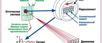
How does an IR detector work?
The operating principle of an infrared motion sensor is based on recording changes in the density of thermal radiation in the controlled space using a Fresnel lens. As long as the infrared background of the room is stable, the sensor is in standby mode. As soon as a person enters the room, the level of thermal radiation changes the balance towards increasing the IR flux. This will cause a change in resistance in the lens, which will give a signal to the relay, which in turn will turn on the light. When the movements of people in the room stop, the reverse process will occur, and then the light in the room will go out.
Operating principle of the IR sensor:
Photo of the sensor board
Photo to reader Dmitry's comment dated May 3, 2022.
Photo of motion sensor board for repair
Instead of a 100 Ohm 1W SMD resistor (designation 101). I installed a Soviet 2-watt one on the remote wires.
Replacing a resistor when repairing a motion sensor