Description of the process of disconnecting the AC electrical circuit during a short circuit
When the switch contacts open, the current is not interrupted. According to Lenz's law, an emf EL=-Ldi/dt appears in the circuit, preventing a change in current. The latter finds a path for itself through the gas gap between the diverging contacts of the switch, which is blocked by an electric arc. To interrupt the current, the arc must be extinguished. In alternating current circuits, favorable conditions for arc extinction occur every time the current reaches zero, i.e. 2 times during each period. The diameter of the arc column, temperature and ionization of the gas decrease sharply. At some point in time, the current comes to zero and the arc discharge stops. However, the chain has not yet been broken.
After zero current in the gas gap, which is still somewhat ionized, the deionization process continues, i.e. the process of transforming it from a conductor into a dielectric, and in the electrical circuit the process of restoring the voltage at the switch contacts from a relatively small arc voltage to the mains voltage begins. These processes are interconnected. The outcome of the interaction of the arc gap with the electrical circuit depends on the relationship between the energy supplied to the gap and the energy losses in it, which depend on the arc extinguishing device of the switch.
If energy losses predominate throughout the entire transient process, the arc will not occur again and the circuit will be interrupted. Otherwise, the arc will arise again and the current will flow for another half of the period, after which the interaction process will repeat. The function of the switch is not so much to “extinguish” the arc, but rather to exclude the possibility of its re-ignition by effectively deionizing the gap by various artificial means. This uses the exceptional property of gas - quickly, within a few microseconds, to transform from a conductor into a dielectric capable of withstanding the restoring network voltage.
To understand the design and operation of switches, it is necessary to become familiar with the physical processes in the arc gap during the shutdown process. This article discusses arc extinguishing methods in air and oil circuit breakers.
Physical processes in the arc gap of a switch at high pressure
An electric arc, or more precisely an arc discharge, is called an independent discharge in a gas, i.e. a discharge occurring without an external ionizer, characterized by a high current density and a relatively small voltage drop at the cathode. Below we consider the high pressure arc, i.e. arc discharge at atmospheric and higher pressure.
The following arc discharge areas are distinguished:
- area of cathode voltage drop;
- area near the anode;
- arc pillar.
The region of the cathode voltage drop is a thin layer of gas at the cathode surface. The voltage drop in this layer is 20-50 V, and the electric field strength reaches 105106 V/cm. The energy supplied from the network to this area is used to release electrons from the cathode surface.
The mechanism for releasing electrons can be twofold:
- thermionic emission with refractory and refractory electrodes (tungsten, coal), the temperature of which can reach 6000 K and higher
- field emission, i.e. the ejection of electrons from the cathode by the action of a strong electric field when the cathode is “cold”.
The current density at the cathode reaches 3000-10000 A/cm5. The current is concentrated in a small brightly lit area called the cathode spot. The released electrons move through the arc column to the anode.
At the anode, positive ions become accelerated towards the cathode. The electrons go to the anode and form a negative charge in a thin layer. The voltage drop at the anode is 10-20 V.
Processes in the arc column are of greatest interest when studying switches, since various types of influence on the arc column are used to extinguish the arc. The latter is plasma, i.e. an ionized gas with a very high temperature and equal amounts of electrons and positive ions per unit volume.
The high temperature in the arc column is created and maintained by electrons and ions that participate in the thermal chaotic movement of neutral molecules and atoms, but also have a directed movement in the electric field along the axis of the arc, determined by the sign of the charge of the particles. This movement is prevented by neutral gas. Frequent collisions of electrons and ions with neutral particles occur. Since the mean free path of electrons at high pressure is small, the energy loss during elastic collisions with molecules and atoms per collision is small and insufficient to ionize particles. However, the number of collisions that electrons undergo is very large. As a result, the energy of the electrons is transferred to the neutral gas in the form of heat.
The average energy of the “electron gas” cannot significantly exceed the average energy of the neutral gas, since the additional energy acquired by electrons and ions in their directed motion along the axis of the meadow column is small compared to the thermal energy of the gas. Consequently, ions, electrons, as well as neutral atoms and molecules are in thermal equilibrium. In this case, the specific ionization of the arc column is completely determined by temperature, and when one of these quantities changes, the other inevitably changes.
Because at high gas pressure atoms and molecules overwhelmingly outnumber electrons and have almost the same high temperature, most excited and ionized atoms and molecules are produced by collisions between neutral particles rather than by collisions with electrons. Thus, electrons do not ionize directly through collisions with neutral particles (as happens in a vacuum), but indirectly, increasing the temperature of the gas in the arc column. This ionization mechanism is called thermal ionization. The source of energy required for thermal ionization is an electric field.
There are energy losses in the arc column, which in a steady state are balanced by the energy received from the network. The bulk of the energy is carried away from the arc column by excited and ionized atoms and molecules. Due to the difference in the concentrations of charged particles in the arc column and the surrounding space, as well as the temperature difference, the ions diffuse to the surface of the arc column, where they are neutralized. These losses must be compensated by the formation of new ions and electrons associated with the expenditure of energy. In steady state, the voltage gradient in the arc column is always such that the ionization that occurs compensates for the loss of electrons through recombination. The voltage gradient depends on the properties of the gas, the state in which it is located (quiet, turbulent), as well as pressure and current. As gas pressure increases, the voltage gradient increases due to a decrease in the free path of electrons. As the current increases, the voltage gradient decreases, which is explained by an increase in the cross-sectional area and temperature of the arc column. The arc column tends to take on a cross-section such that, under the conditions under consideration, energy losses are minimal.
Current-voltage characteristics of the arc
The dependence of the voltage gradient E = dU/dl in the arc column on the current with a very slow change in the latter is a static characteristic of the arc (Fig. 1, a), depending on the pressure and properties of the gas.
Fig.1. Current-voltage characteristics of the arc: a - static characteristic; b - dynamic characteristics
In a steady state, each point of the characteristic corresponds to a certain cross section and temperature of the arc column. When the current changes, the arc column must change its cross-section and temperature in relation to the new conditions. These processes take time, and therefore the new steady state does not occur immediately, but with some delay. This phenomenon is called hysteresis.
Let's assume that the current suddenly changes from the value I1 (point 1) to the value I2 (point 2). At the first moment, the arc will retain its cross sections and temperature, and the gradient will decrease (point 2′). The power supplied will be less than that required to carry current I2. Therefore, the cross section and temperature will begin to decrease, and the gradient will increase, until a new steady state occurs at point 2 on the static characteristic. If the current suddenly increases from value I1 to value I3, the voltage gradient will increase (point 3′). The power supplied to the arc will be greater than that required to conduct current I3. Therefore, the cross section and temperature of the column will begin to increase, and the voltage gradient will decrease until a new steady state occurs at point 3 on the static characteristic.
When the current changes smoothly at a certain speed, the voltage gradient does not have time to follow the current change in accordance with the static characteristic. When the current increases, the voltage gradient exceeds the values determined by the static characteristic, and when the current decreases, the voltage gradient is less than these values. Curves E=f(I) when the current changes at a certain speed represent the dynamic characteristics of the arc (solid lines in Fig. 1, b).
The position of these characteristics in relation to the static characteristic (see dotted curve) depends on the rate of change of current. The slower the current change occurs, the closer the dynamic characteristic is to the static one. Under a given arcing condition there can be only one static characteristic. The number of dynamic characteristics is not limited.
When analyzing electrical circuits, it is customary to operate with the concept of resistance. Therefore, they also talk about arc resistance, meaning by this the ratio of voltage at the electrodes to current. Arc resistance is not constant. It depends on the current and many other factors. As the current increases, the arc resistance decreases.
Fig.2. Arc voltage with alternating current: a - arc voltage as a function of current; 6 - arc voltage as a function of time
The current-voltage characteristic of an alternating current arc is shown in Fig. 2, a. During the quarter period, when the current increases, the voltage curve lies above the static characteristic. The next quarter of the period, when the current decreases, the voltage curve lies below the static characteristic.
The arc ignites at points 1 and 3 and goes out at points 2 and 4. Figure 2,b shows the characteristics of the arc as a function of time. Intervals 2-3 and 4-1 correspond to an unstable state in which there is intense interaction of the arc with the circuit constants R, L and C. These short time intervals, which last a few microseconds, are used to intensively deionize the gap between the switch contacts to prevent new arc ignition. Depending on the conditions, the interaction process can end in two ways: either the arc will go out and the circuit will be interrupted, or the arc will arise again and the interaction process will be repeated after half a period under more favorable conditions.
§92. Electric arc and methods of extinguishing it
Physical basis of arc combustion . When the contacts of an electrical device open, an electric arc occurs due to ionization of the space between them. The gap between the contacts remains conductive and the flow of current through the circuit does not stop.
For ionization and arc formation, it is necessary that the voltage between the contacts be approximately 15-30 V and the circuit current 80-100 mA.
When the space between the contacts is ionized, the gas (air) atoms filling it disintegrate into charged particles - electrons and positive ions. The flow of electrons emitted from the surface of the contact, which is under a negative potential (cathode), moves towards the positively charged contact (anode); the flow of positive ions moves to the cathode (Fig. 303, a).
The main current carriers in the arc are electrons, since positive ions, having a large mass, move much slower than electrons and therefore transfer much less electrical charges per unit time. However, positive ions play a large role in the arcing process. Approaching the cathode, they create a strong electric field near it, which affects the electrons present in the metal cathode and pulls them out from its surface. This phenomenon is called field emission (Fig. 303, b). In addition, positive ions continuously bombard the cathode and give it their energy, which turns into heat; in this case, the cathode temperature reaches 3000–5000 °C.
As the temperature increases, the movement of electrons in the cathode metal accelerates, they acquire greater energy and begin to leave the cathode, flying into the environment. This phenomenon is called thermionic emission. Thus, under the influence of auto- and thermionic emission, more and more electrons enter the electric arc from the cathode.
When moving from the cathode to the anode, electrons, colliding with neutral gas atoms on their way, split them into electrons and positive ions (Fig. 303, c). This process is called impact ionization. The new, so-called secondary electrons that appear as a result of impact ionization begin to move towards the anode and, in their movement, split more and more new gas atoms. The considered process of gas ionization has an avalanche-like character, just as one stone thrown from a mountain captures more and more stones along its path, giving rise to an avalanche. As a result, the gap between the two contacts is filled with more electrons and positive ions. This mixture of electrons and positive ions is called plasma. In the formation of plasma, thermal ionization plays a significant role, which occurs as a result of an increase in temperature, causing an increase in the speed of movement of charged gas particles.
The electrons, ions and neutral atoms that form the plasma continuously collide with each other and exchange energy; in this case, some atoms under the impacts of electrons come into an excited state and emit excess energy in the form of light radiation. However, the electric field acting between the contacts causes the bulk of the positive ions to move towards the cathode, and the bulk of the electrons to the anode.
In a direct current electric arc in a steady state, thermal ionization is decisive. In an alternating current arc, when the current passes through zero, impact ionization plays a significant role, and during the rest of the arc burning time, thermal ionization plays a significant role.
When the arc burns, simultaneously with the ionization of the gap between the contacts, the reverse process occurs. Positive ions and electrons, interacting with each other in the intercontact space or when they hit the walls of the chamber in which the arc is burning, form neutral atoms. This process is called recombination; when ionization stops, recombination leads to the disappearance of electrons and ions from the interelectrode space - its deionization occurs. If recombination occurs on the chamber wall, it is accompanied by the release of energy in the form of heat; During recombination in the interelectrode space, energy is released in the form of radiation.
Rice. 303. The direction of movement of electrons and positive ions in an electric arc (o), the occurrence of field emission from the cathode (b) and impact ionization of gas atoms in the space between the contacts (c): 1,2 - primary and secondary electrons; 3—gas atom; 4 - positive ion
When it comes into contact with the walls of the chamber in which the contacts are located, the arc cools, which. leads to increased deionization. Deionization also occurs as a result of the movement of charged particles from the central regions of the arc with a higher concentration to the peripheral regions with a low concentration. This process is called diffusion of electrons and positive ions.
The arc combustion zone is conventionally divided into three sections: the cathode zone, the arc shaft and the anode zone. In the cathode zone, intense electron emission occurs from the negative contact; the voltage drop in this zone is about 10 V.
A plasma with approximately the same concentration of electrons and positive ions is formed in the arc barrel. Therefore, at each moment of time, the total charge of the positive ions of the plasma compensates for the total negative charge of its electrons. The high concentration of charged particles in the plasma and the absence of an electrical charge in it determine the high electrical conductivity of the arc barrel, which is close to the electrical conductivity of metals. The voltage drop in the arc shaft is approximately proportional to its length. The anode zone is filled mainly with electrons coming from the arc shaft to the positive contact. The voltage drop in this zone depends on the arc current and the size of the positive contact. The total voltage drop in the arc is 15-30 V.
The dependence of the voltage drop Udg acting between the contacts on the current I passing through the electric arc is called the current-voltage characteristic of the arc (Fig. 304a). The voltage Uз, at which arc ignition is possible at current I = 0, is called ignition voltage. The ignition voltage value is determined by the material of the contacts, the distance between them, temperature and environment. After the occurrence
Rice. 304. Current-voltage characteristics of a direct current arc (a) and curves of changes in voltage and current (b) when burning an alternating current arc
During an electric arc, its current increases to a value close to the load current that flowed through the contacts before shutdown. In this case, the resistance of the intercontact gap drops faster than the current increases, which leads to a decrease in the voltage drop Udg. The arc burning mode corresponding to curve a is called static.
When the current decreases to zero, the process corresponds to curve b and the arc stops with a lower voltage drop than the ignition voltage. The voltage Ug at which the arc goes out is called the extinction voltage. It is always less than the ignition voltage due to an increase in the temperature of the contacts and an increase in the conductivity of the intercontact gap. The greater the rate of current reduction, the lower the arc extinction voltage at the moment the current stops. Volt-ampere characteristics b and c correspond to a decrease in current at different rates (for curve c more than for curve b), and straight line d corresponds to an almost instantaneous decrease in current. This nature of the current-voltage characteristics is explained by the fact that with a rapid change in current, the ionization state of the intercontact gap does not have time to follow the change in current. It takes a certain time for the gap to deionize, and therefore, despite the fact that the current in the arc has dropped, the conductivity of the gap remains the same, corresponding to a high current.
The current-voltage characteristics b - d, obtained when the current quickly changes to zero, are called dynamic. For each contact gap, electrode material and medium, there is one static arc characteristic and many dynamic ones, contained between curves a and d.
When an alternating current arc burns during each half-cycle, the same physical processes take place as in a direct current arc. At the beginning of the half-cycle, the voltage on the arc increases according to a sinusoidal law to the value of the ignition voltage Uз - section 0-a (Fig. 304, b), and then after the arc occurs, it drops as the current increases - section a - b. In the second part of the half-cycle, when the current begins to decrease, the arc voltage again increases to the value of the extinction voltage Ug when the current drops to zero - section b - c.
During the next half-cycle, the voltage changes sign and increases according to a sinusoidal law to the ignition voltage value corresponding to point a' of the current-voltage characteristic. As the current increases, the voltage decreases and then increases again as the current decreases. The arc voltage curve, as seen in Fig. 304, b, has the shape of a cut sinusoid. The process of deionization of charged particles in the gap between the contacts lasts only a small fraction of the period (sections 0 - a and c - a') and, as a rule, does not end during this time, as a result of which the arc occurs again. The final extinguishing of the arc will take place only after a series of re-ignitions during one of the subsequent current zero crossings.
The resumption of the arc after the current passes through zero is explained by the fact that after the current declines to zero, the ionization existing in the arc barrel will not disappear immediately, since it depends on the temperature of the plasma in the residual arc barrel. As the temperature decreases, the electrical strength of the intercontact gap increases. However, if at some point in time the instantaneous value of the applied voltage is greater than the breakdown voltage of the gap, then its breakdown will occur, an arc will occur and a current of a different polarity will flow.
Arc extinction conditions. The conditions for extinguishing a DC arc depend not only on its current-voltage characteristics, but also on the parameters of the electrical circuit (voltage, current, resistance and inductance), which the device contacts turn on and off. In Fig. 305, and the current-voltage characteristic of the arc is shown
Rice. 305. Current-voltage characteristics of the arc during stable combustion (a) and quenching (b)
(curve 1) and the dependence of the voltage drop across the resistor R connected to this circuit (straight line 2). In steady state, the voltage U and the current source is equal to the sum of the voltage drops in the arc Udg and IR across the resistor R. When the current in the circuit changes, e is added to them. d.s. self-induction ±eL (shown as shaded ordinates). Long-term arc burning is possible only in the modes corresponding to points A and B, when the voltage Ui - IR applied to the gap between the contacts is equal to the voltage drop Udg. In this case, in the mode corresponding to point A, the arc combustion is unstable. If, when the arc burns at this point of the characteristic, the current for some reason increases, then the voltage Udg will become less than the applied voltage Ui - IR. An excess of applied voltage will cause an increase in current, which will increase until it reaches the value Iv.
If in the mode corresponding to point A, the current decreases, the applied voltage Ui - IR will become less than Udg and the current will continue to decrease until the arc goes out. In the mode corresponding to point B, the arc burns steadily. When the current increases above Iv, the voltage drop in the arc Udg will become greater than the applied voltage Ui - IR and the current will begin to decrease. When the current in the circuit becomes less than Iv, the applied voltage Ui - IR will become greater than Udg and the current will begin to increase.
Obviously, in order to ensure arc extinction over the entire specified range of changes in current I from the highest value to zero when the circuit is turned off, it is necessary that the current-voltage characteristic 1 be located above straight line 2 for the circuit being turned off (Fig. 305,b). Under this condition, the voltage drop in the arc Udg will always be greater than the voltage Ui - IR applied to it and the current in the circuit will decrease.
The main means of increasing the arc voltage drop is to increase the arc length. When opening low-voltage circuits with relatively small currents, extinguishing is ensured by an appropriate choice of contact solution between which an arc occurs. In this case, the arc goes out without any additional devices.
For contacts that break power circuits, the length of the arc required for extinguishing is so great that it is no longer possible to practically implement such a solution of contacts. In such electrical devices, special arc extinguishing devices are installed.
Arc extinguishing devices. Methods for extinguishing the arc may be different, but they are all based on the following principles: forced lengthening of the arc; cooling the intercontact gap using air, vapor or gases; division of the arc into a number of separate short arcs.
As the arc lengthens and moves away from the contacts, the voltage drop in the arc column increases and the voltage applied to the contacts becomes insufficient to maintain the arc.
Rice. 306. Arc extinguishing device with protective horns (a) and arc extinguishing (b)
Cooling the intercontact gap causes increased heat transfer from the arc column into the surrounding space, as a result of which charged particles, moving from the inside of the arc to its surface, accelerate the deionization process.
Dividing the arc into a number of separate short arcs leads to an increase in the total voltage drop in them and the voltage applied to the contacts becomes insufficient to sustainably maintain the arc, so it is extinguished.
The principle of extinguishing by lengthening the arc is used in devices with protective horns and in switches. The electric arc that occurs between contacts 1 and 2 (Fig. 306, a) when they open, rises upward under the action of the force FB created by the flow of air heated by it, stretches and lengthens on the diverging fixed horns, which leads to its extinguishing. The lengthening and extinguishing of the arc is also facilitated by the electrodynamic force created as a result of the interaction of the arc current with the magnetic field arising around it. In this case, the arc behaves like a conductor with current located in a magnetic field (Fig. 307, a), which, as was shown in Chapter III, tends to push it out of the field.
To increase the electrodynamic force Fe acting on the arc, in some cases a special arc-extinguishing coil 2 is included in the circuit of one of the contacts 1 (Fig. 307,b), creating a strong magnetic field in the arc formation zone, magnetically
Rice. 307. The principle of magnetic blast (a) and arc suppression device with arc suppression coil (b)
Rice. 308. Arc chambers
the filament flow F, interacting with the arc current I, ensures intensive blowing and extinguishing of the arc. The rapid movement of the arc along the horns 3, 4 causes its intense cooling, which also contributes to its deionization in chamber 5 and extinction.
Some devices use methods of forced cooling and stretching of the arc with compressed air or other gas.
When contacts 1 and 2 open (see Fig. 306, b), the resulting arc is cooled and blown out of the contact area by a jet of compressed air or gas with a force FB.
An effective means of cooling the electric arc and then extinguishing it are arc extinguishing chambers of various designs (Fig. 308). An electric arc, under the influence of a magnetic field, air flow or other means, is driven into narrow cracks or a labyrinth of the chamber (Fig. 308, a and b), where it is in close contact with its walls 1, partitions 2, gives off heat to them and goes out. Widely used in electrical appliances. p.s. labyrinthine-slit chambers are found, where the arc is lengthened not only by stretching between the contacts, but also by its zigzag curvature between the partitions of the chamber (Fig. 308, c). A narrow gap 3 between the walls of the chamber promotes cooling and deionization of the arc.
Arc extinguishing devices, the action of which is based on dividing the arc into a number of short arcs, include a deion grating (Fig. 309, a), built inside the arc extinguishing chamber.
The deion grid is a set of a number of individual steel plates 3, isolated relative to each other. The electric arc that occurs between opening contacts 1 and 2 is divided by the grid into a number of shorter arcs connected in series. To maintain the arc without splitting, a voltage U is required equal to the sum of the near-electrode (anode and cathode) voltage drop Ue and the voltage drop in the arc column Ust.
When one arc is divided into n short arcs, the total voltage drop in the column of all short arcs will still be equal to nUe as for one common arc, but the total near-electrode voltage drop in all arcs will be equal to nUe. Therefore, to maintain the arc in this case, voltage will be required
U = nUе + Ust.
The number of arcs n is equal to the number of grid plates and can be chosen such that the possibility of stable arc burning at a given voltage U is completely excluded. This damping principle is effective for both direct and alternating current. When the alternating current passes through zero, a voltage of 150-250 V is required to maintain the arc. In this regard, the number of plates can be chosen significantly less than with direct current.
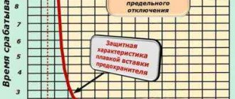
In fuses with a filler, when the insert melts and an electric arc occurs due to the increased gas pressure in the cartridge, ionized particles move in the transverse direction. At the same time, they fall between the filler grains, cool and deionize. The filler grains, moving under the influence of excess pressure, break the arc into a large number of microarcs, which ensures their extinguishing.
In fuses without filler, the body is often made of a material that releases gas abundantly when heated. Such materials include, for example, fiber. When it comes into contact with an arc, the housing heats up and releases a gas that helps extinguish the arc. The arc in AC oil switches is extinguished in a similar way (Fig. 309, b), with the only difference being that instead of dry filler, non-flammable oil is used here. When an arc occurs at the moment of opening the movable 1, 3 and fixed 2 contacts, its extinguishing occurs under the influence of two factors: the release of a large amount of hydrogen, which does not support combustion (the oil used for this purpose contains 70-75% hydrogen), and intensive cooling of the arc with oil due to its high heat capacity. The arc goes out at the moment when the current is zero. Oil not only promotes accelerated arc extinguishing, but also serves as insulation for live and grounded parts of the structure. Oil is not used to extinguish an arc in a DC circuit, since under the action of an arc it quickly decomposes and loses its insulating qualities.
In modern electrical apparatus, arc extinguishing is often carried out by combining two or more considered
Rice. 309. Arc quenching in a deionic grating (a) and in oil (b)
Rice. 310. Current change curve when the emergency current is switched off by a circuit breaker
above methods (for example, using an arc suppressor coil, protective horns and a deion grid).
The conditions for extinguishing the electric arc determine the breaking capacity of protective devices. It is characterized by the highest current that can turn off the device with a certain arc extinguishing time.
When there is a short circuit in the electrical circuit connected to a source of electrical energy, the current in the circuit increases along curve 1 (Fig. 310). At moment t1, when it reaches the value to which the protective device is adjusted (set current Iу), the device is triggered and turns off the protected circuit, as a result of which the current decreases along curve 2.
The time counted from the moment the signal is given to turn off (or turn on) the device until the moment the contacts begin to open (or close) is called the device’s own response time tс. When disconnecting, the moment the contacts begin to open corresponds to the appearance of an arc between the diverging contacts. In circuit breakers, this time is measured from the moment the current reaches the set value t1 until the moment an arc appears between the contacts t2. The arc burning time tdg is the time from the moment the arc appears t2 to the moment the current t3 stops flowing. The total shutdown time tп is the sum of its own time and the arcing time.
Arc extinction in air circuit breakers
In air circuit breakers, the arc is extinguished in a high-pressure air stream. The switch extinguishing device (Fig. 3a) is a chamber in which two nozzles are placed, which simultaneously serve as contacts. The exhaust sides of the nozzles are connected to the low pressure area. When the contacts are separated, due to the pressure difference, an air flow occurs, directed into the nozzles symmetrically in both directions.
Fig.3. Arcing device of an air circuit breaker with double-sided blast: a - diagram; b - pressure distribution along the axis
Figure 3b shows the pressure distribution along the axis. In the middle of the gap between the nozzles there is a flow stagnation point, the pressure at which is indicated by po.
On both sides of this point the pressure decreases and reaches approximately half po at the nozzle necks. Behind the throats, the pressure continues to drop to exhaust pressure.
The arc extinguishing process proceeds as follows. An arc appears between the opening contacts, which, under the action of the air flow, is quickly transferred along the axis. In this case, the arc support spots move inside the nozzles along the flow, as shown in Fig. 3. The arc in the space between the nozzles has a cylindrical shape.
Fig.4. Temperature distribution in the transverse direction in the area between the nozzles: a - arc; c - thermal boundary layer
The temperature distribution in the transverse direction is shown in Fig. 4. In the arc zone a it is approximately 20,000 K and drops sharply towards the thermal boundary layer b formed near the arc. Here the temperature varies from 2000 K to cold air temperature. As the current approaches zero, the diameter of the cylindrical part of the arc rapidly decreases. When the current is zero, it is less than 1 mm. However, the temperature in this part of the arc is still very high (15000 K).
The most important factor contributing to arc extinction is turbulence in the boundary layer between the arc and the relatively cold air surrounding it. Due to the high temperature of the arc, the gas density in the column is approximately 20 times less than in the environment. Therefore, the gas velocity inside the arc column is significantly higher than the velocity in the neighboring layers (the velocity is inversely proportional to the square root of the density). Due to the diffusion of particles from an area with high speed to an area with low speed and back, significant shear forces arise in the boundary layer, vortices are formed and the entire volume acquires high turbulence. A relatively cold non-ionized gas is introduced into the arc column, as a result of which the column loses its homogeneity. It splits into thousands of the finest conductive threads, continuously changing their shape and position (Fig. 5).
Fig.5. The influence of turbulence on the arc column near zero current (scheme)
They have a high temperature and high specific ionization and are surrounded by cold, weakly ionized gas. It is known that the rate of diffusion from a cylindrical volume is inversely proportional to the square of the diameter. The thinner the ionized filaments, the faster the exchange of particles with the surrounding colder and less ionized environment occurs. Turbulence increases diffusion many times over. It manifests itself especially sharply in the throats of the nozzles, where the plasma speed is maximum - 6000 m/s. After zero current, for a short period of time, measured in microseconds, the conductive channel disintegrates and a further decrease in temperature is determined by the thermal boundary layer, the cooling of which occurs much more slowly.
Fig.6. Equivalent diagram explaining the influence of arc resistance and capacitance
Fig.7. Interaction of the arc with the electrical circuit
The arc resistance and capacitance connected parallel to the arc gap have a significant influence on the shutdown process (Fig. 6). If we neglect the arc resistance, the current i0=Imsinɷt approaches zero almost linearly (Fig. 7). However, the arc resistance is not zero. Therefore, the current iB in the arc gap of the switch decreases:
(1)
where t0 is the moment of contact opening.
As can be seen from the figure, the arc voltage changes in accordance with the current-voltage characteristic. The rate of current decrease decreases significantly during the last 5...10 μs before it reaches zero. This time is small, but it is several times greater than the arc time constant and therefore significantly affects the state of the arc at zero current (point 1). The arc goes out easily. The arc resistance also modifies the PVN curve. The voltage recovery process begins at point 1; the voltage reaches its maximum at point 2 when iL=iC=0.
Stage of possible thermal breakdown
If the temperature of the gas in the gap does not decrease to a certain critical value determined by the gas property and pressure, the gap will retain its conductivity after zero current (point 1) and under the influence of the PVN a residual conductivity current will arise (Fig. 8).
Fig.8. Arc extinction with a delay caused by the appearance of residual conduction current
Under favorable conditions, it is small and quickly fades (point 2). However, if the cooling process is not intense enough, the residual conduction current increases; The plasma is reheated, the ionization process resumes, and the arc occurs again. This phenomenon is called thermal breakdown, since electrical breakdown is impossible, since the gap is ionized and has not yet acquired electrical strength.
Whether such a breakdown occurs or not depends on the outcome of two interrelated processes occurring in the gap, one of which is determined by the time integral of the supplied power (the product of current and voltage across the gap), and the second by the time integral of losses caused by thermal conductivity and convection. This means that the interaction process will continue until the current disappears or the arc occurs again. The phenomenon of thermal breakdown is typical for the first 20 μs after zero current under conditions when the speed of voltage recovery is high, for example, with unremoved short circuits.
Stage of possible electrical breakdown
If thermal breakdown does not occur, the intercontact gap continues to be exposed to the influence of the PVN. The arc channel has an even higher temperature and lower density. A few hundred microseconds after zero current, when the PVN reaches its maximum value, the stage of possible electrical breakdown begins. It is based not on energy balance, but on the process of electron formation in an electric field. If the increase in electron concentration exceeds a certain critical value, a spark will form, which will turn into an arc discharge.
What is an electric arc?
This mysterious phenomenon was first described by the Russian scientist V. Petrov. He created an electric arc using a battery consisting of thousands of copper and zinc plates. Studying the process of igniting an arc with direct current, the scientist came to the conclusion that the air gap between the electrodes under certain conditions becomes electrically conductive.
One of the conditions for the occurrence of electrical breakdown is a sufficiently high potential difference at the ends of the electrodes. The higher the voltage, the larger the gas gap the discharge can bridge. In this case, an electrically conductive gas column is formed, which becomes very hot during the burning of the arc.
Rice. 2. Electric arc
A reasonable question arises : “Why does air, which is an excellent insulator in its normal state, suddenly become a conductor?”
There can be only one explanation - charge carriers are formed in the arc barrel, capable of moving under the influence of an electric field. Since there are no free electrons in air, unlike metals, only one conclusion suggests itself - ionization of gases (see Fig. 3). That is, starting the process of gas saturation with ions that are carriers of electric charge.
Rice. 3. Physics of the electric arc
Air ionization occurs under the influence of various types of radiation, including X-ray and cosmic irradiation. Therefore, there are always small amounts of ions in the air. But since the ions almost immediately recombine (turn into neutral atoms and molecules), the concentration of charged particles is always tiny. It is impossible to produce an arc flash at such a concentration.
For an arc discharge to occur, an avalanche-like ionization process is required. It can be caused by the strong heating of the gas that occurs during ignition.
When the contacts open, electrons are emitted and accumulate in a very small space. Under the influence of electric field strength, negative charges rush towards the electrode with a positive sign.
When the breakdown voltage is reached, a spark discharge occurs between the electrodes, heating the area between the electrodes. If the current is large enough, then the amount of heat will be sufficient to trigger an avalanche-like process of air ionization.
In an area called the arc gap, a barrel is formed, called an arc column, consisting of hot conductive plasma. A current flows through this barrel, maintaining the heating of the plasma. This is how the arc discharge ignites.
Saturation of the plasma barrel with ions of different signs leads to a significant increase in the current density, as well as to the recombination of some of the ions. Warming up the plasma also leads to an increase in pressure in the barrel. Therefore, some of the ions escape into the surrounding space.
If the formation of new charges is not maintained, the arc will be extinguished. As we have already found out, stable combustion is accompanied by 2 factors: the presence of voltage between the electrodes and maintaining a high plasma temperature. Excluding one of them will lead to arc extinguishing.
Thus, we can formulate the definition of an electric arc . Namely, an electric arc is a type of spark discharge, accompanied by a high current density, burning duration, and a small voltage drop across the barrel, characterized by increased gas pressure in which a high temperature is maintained.
An electric arc differs from a conventional discharge in that it burns longer.
Arc extinction in oil circuit breakers
In oil switches, the contacts open in oil, but due to the high temperature of the arc formed between the contacts, the oil decomposes and the arc discharge occurs in a gaseous environment. Approximately half of this gas (by volume) is oil vapor. The rest consists of hydrogen (70%) and hydrocarbons of various compositions. These gases are flammable, but combustion in oil is impossible due to the lack of oxygen. The amount of oil decomposed by the arc is small, but the volume of gases produced is large. One gram of oil gives approximately 1500 cm3 of gas, reduced to room temperature and atmospheric pressure.
Arc extinguishing in oil switches occurs most effectively when using extinguishing chambers, which limit the arc zone, contribute to an increase in pressure in this zone and the formation of a gas blast through the arc column. Figure 9 shows a diagram of the simplest extinguishing chamber.
Fig.9. Diagram of the simplest extinguishing chamber of an oil switch
During the shutdown process, contact rod 1 moves downwards. An arc occurs between pins 1 and 2. Intense gas formation occurs and the pressure in the chamber quickly increases. The relatively cold gas formed on the surface of the oil mixes with the arc plasma. The boundary layer enters a turbulent state, promoting deionization. However, the arc cannot go out until the distance between the contacts reaches a certain minimum value determined by the recovery voltage. This minimum gap occurs when the moving contact is still in the chamber. When the rod leaves the chamber, the gases are thrown out with force. A gas blast occurs, directed along the axis, helping to extinguish the arc.
After the arc is extinguished, the contact rod continues its movement to ensure the required insulation distance in the off position.
The arc voltage of an oil circuit breaker is at least 3 times that of an air circuit breaker. The electrical strength of the gap is restored faster (at a rate of about 2 kV/µs). Therefore, with the same short-circuit current, the arc extinguishing device of the oil circuit breaker can be designed for twice the voltage and twice the characteristic impedance than the air blast device.