- September 12, 2020
- Repair Tips
- Ivan Gresko
Many radio amateurs and home craftsmen are familiar with this heating device. It can be used to connect various parts made of ferrous and non-ferrous metals. Owners are often interested in the question: how to repair a soldering iron at home? The fact is that this tool can fail as a result of improper handling. Of course, you can take it to a workshop and have it done by a professional. However, many owners prefer to do it on their own.
How to fix a soldering iron? This is especially of interest to those who have just begun to master this heating device. In general, this task will not be difficult to cope with if you identify the cause of the breakdown and strictly adhere to a certain algorithm of actions. Information on how to repair a soldering iron at home is presented in this article.
Components of the tool
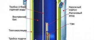
Before you are interested in how to repair a soldering iron at home, you should know how it works. In this case, if there is a breakdown, it will be easier for you to determine the cause and fix it. The soldering iron device is represented by the following elements:
- Copper rod. It is wrapped in insulating material and housed in a steel tube.
- Heater. This task is performed by nichrome thread.
- Sting. They use solder to directly connect metal parts.
- With a pen. Thanks to it, the master can hold the soldering iron.
- Cord equipped with a plug.
Description of design
The copper rod is an effective conductor of heat that flows from the heater to the tip. The rod is located in a steel tube wrapped in mica or glassy tissue. A wire is wound over the mica, which acts as a heating element. To prevent heat loss and short circuit, the nichrome winding is insulated, covered with asbestos for this purpose. The ends of the spiral are connected to the conductors of the power cord. To make the design more reliable and the connection point not to overheat from the heat generated, the nichrome spiral is bent in half and folded in half. Additionally, the point of contact of the spiral with the copper wire is crimped using an aluminum plate. In addition, the twisting area is covered with an insulating tube. All of the above elements are housed in a metal casing. It is mounted on a handle, which can be made of wood or thermoplastic. Inside the handle there is a special channel for the electrical cord. The housing is fixed to the metal tube using overlay rings. Those who are interested in how to repair a soldering iron at home should also know about the technical characteristics of the electrical appliance.
How does the device work?
Those who do not know how to repair a soldering iron with their own hands should familiarize themselves with the principle of operation of an electrical device. The soldering iron functions by converting electricity into heat. As a result, heat is transferred through the heated spiral to the rod, as a result of which the tip becomes heated. You should know that in the area where soldering is carried out, the temperature varies from 400 to 4500 °C. As a result, a mixture of viscous-liquid consistency is formed. Subsequently, it fills the cavity between the parts being soldered. When the mixture cools, the metal parts are securely connected.
About voltage
If there is a need to repair the device, take into account the voltage indicator. Depending on the model, its value may be:
- 220 V. This value is mainly found in domestic models.
- 12-42 V. Devices with a reduced voltage transformer are used in conditions with high levels of dust or humidity in order to protect the technician from electric shock.
- 5 V. Miniature USB soldering irons have this indicator.
Winding calculation
Repairing a soldering iron in most cases comes down to a procedure that allows you to rewind a burnt nichrome winding. When replacing it, it is important to correctly select the thickness and diameter of the nichrome wire, as well as the number of turns in the spiral, which determines the generated thermal power.
When calculating and selecting the required wire diameter, we proceed from the resistance value of the soldering iron’s heating winding, which, in turn, is determined by its operating power (supply voltage).
To determine the initial indicator (winding resistance), special tables are used.
| 220 | 127 | 36 | 12 | |
| 35 | 1380 ± 10% | 460 ± 10% | 37 | 4,1 |
| 50 | 970 » | 320 » | 26 | 2,9 |
| 65 | 750 » | 245 » | 20 | 2,2 |
| 90 | 540 » | 180 » | 14,5 | 1,6 |
| 120 | 410 » | 135 » | 10,8 | — |
| 200 | 240 » | 80 » | 6,5 | — |
| 350 | — | — | 3,7 | — |
| 0,20 | 35,3 | 34,1 | ||
| 0,22 | 29,2 | 28,2 | ||
| 0,25 | 22,6 | 21,8 | ||
| 0,28 | 18,0 | 17,4 | ||
| 0,30 | 15,3 | 15,2 | ||
| 0,32 | 13,8 | 13,3 | ||
| 0,35 | 11,3 | ID | ||
| 0,40 | 8,59 | 8,52 | ||
| 0,45 | 6,98 | 6,73 | ||
| 0,50 | 5,66 | 5,45 | ||
| 0,60 | 4,07 | 3,82 | ||
| 0,70 | 2,91 | 2,84 | ||
| 0,80 | 2,23 | 2,17 | ||
| 0,90 | 1,76 | 1,72 | ||
| 1,00 | 1,42 | 1,39 |
| Table for determining the resistance of a nichrome spiral depending on the power and supply voltage of electrical devices , Ohm | ||||||
| Soldering iron power consumption, W | Soldering iron supply voltage, V | |||||
| 12 | 24 | 36 | 127 | 220 | ||
| 12 | 12 | 48,0 | 108 | 1344 | 4033 | |
| 24 | 6,0 | 24,0 | 54 | 672 | 2016 | |
| 36 | 4,0 | 16,0 | 36 | 448 | 1344 | |
| 42 | 3,4 | 13,7 | 31 | 384 | 1152 | |
| 60 | 2,4 | 9,6 | 22 | 269 | 806 | |
| 75 | 1.9 | 7.7 | 17 | 215 | 645 | |
| 100 | 1,4 | 5,7 | 13 | 161 | 484 | |
| 150 | 0,96 | 3,84 | 8,6 | 107 | 332 | |
| 200 | 0,72 | 2,88 | 6,5 | 80,6 | 242 | |
| 300 | 0,48 | 1,92 | 4,3 | 53,8 | 161 | |
| 400 | 0,36 | 1,44 | 3,2 | 40,3 | 121 | |
| 500 | 0,29 | 1,15 | 2,6 | 32,3 | 96,8 | |
| 700 | 0,21 | 0,83 | 1,85 | 23,0 | 69,1 | |
| 900 | 0,16 | 0,64 | 1,44 | 17,9 | 53,8 | |
| 1000 | 0,14 | 0,57 | 1,30 | 16,1 | 48,4 | |
| 1500 | 0,10 | 0,38 | 0,86 | 10,8 | 32,3 | |
| 2000 | 0,07 | 0,29 | 0,65 | 8,06 | 24,2 | |
| 2500 | 0,06 | 0,23 | 0,52 | 6,45 | 19,4 | |
| 3000 | 0,05 | 0,19 | 0,43 | 5,38 | 16,1 | |
| Table of dependence of linear resistance (one meter) of nichrome wire on diameter | |||||||||||||||||||||||
| Diameter of nichrome wire, mm | 0,05 | 0,07 | 0,08 | 0,1 | 0,2 | 0,3 | 0,4 | 0,5 | 0,60 | 0,7 | |||||||||||||
| Linear resistance, Ohm/m at 20°C | 550 | 280 | 208 | 137 | 34,6 | 15,7 | 8,75 | 5,60 | 3,93 | 2,89 | |||||||||||||
| Diameter of nichrome wire, mm | 0,8 | 0,9 | 1,0 | 1,2 | 1,3 | 1,5 | 2,0 | 2,2 | 2,5 | 3,0 |
| Linear resistance, Ohm/m at 20°C | 2,20 | 1,70 | 1,40 | 0,97 | 0,8 | 0,62 | 0,35 | 0,31 | 0,22 | 0,16 |
Using these tables, you can check the correctness of the winding calculations in order to carry out repairs in the future.
With a fixed supply voltage U and the resistance of the heating device R measured using a tester, the power P consumed by it is calculated using the formula P=(UxU)/R.
About power
This technical characteristic determines the functionality of the soldering iron. For example, for home use to work with wires, a power of 30 W will be sufficient. These soldering irons are mainly used by radio amateurs. Professional installers operate devices with power up to 60 W. Such devices are convenient for soldering wires and cables of various diameters. Soldering irons over 60 W are used in automobile workshops. These soldering irons are suitable for tinning large metal products. It is noteworthy that the higher the power indicator, the larger and heavier the device itself. With increasing power, the size of its tip (sting) also increases. Thus, a soldering iron with more power will heat up the soldering area better. What to do if your electric soldering iron breaks down? How to fix the device?
Operating rules
When working with an electric soldering iron, in order to avoid accidental breakdowns of individual parts, you must adhere to the following rules:
- During soldering, avoid strong mechanical stress on the cord and the electric heater of the device.
- Do not overheat the soldering iron coil (do not leave it on for a long time).
- It is necessary to use a power regulator that allows you to select the required mode for heating the tip.
In conclusion, we note that during operation it is necessary to monitor the condition of the power cord and prevent it from being accidentally damaged by contact with a tip heated to a high temperature.
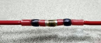
If this cannot be avoided, you should carefully isolate the melted area by placing a cambric over the damaged core and wrapping it with electrical tape.
A simple repair will help get your soldering iron working again. In general, thanks to its simple design, this tool rarely fails.
Repairing a burnt-out soldering iron. Where to begin?
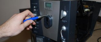
Before you repair the soldering iron yourself, you should disassemble it. This is necessary in order to get to the heating element, namely the nichrome wire. For this purpose, unscrew the mounting bolts and disassemble the device. Overall you will only need to remove two bolts. When they are removed, take out the soldering iron “filling”, which is contained inside the metal case. To do this, you will have to carefully open the case itself. At this stage you must be very careful not to damage the thin and very fragile insulation. If handled carelessly, it may fall apart.
Restoring the heating element
When you get to the heating element, carefully inspect the nichrome wire. It may happen that several turns of wire are burnt out. To restore the heating element you need to do the following. Take an old broken soldering iron and remove a small piece of wire from it. Next, connect it and wind it instead of the burnt out turns. According to experts, when connected without adding wire, the spiral will burn out again due to reduced resistance. You need to wind it so that the turns do not touch each other. Then connect the power cord.
Step-by-step instructions on how to repair it yourself
Soldering iron repair begins with calculating the resistance of the heating element or winding. The voltage and resistance values of an electrical appliance allow you to calculate its power consumption. For example, the resistance in the winding of a soldering iron with a power of 60 W and powered from a 36 V network should be equal to or slightly more than 22 Ohms.
For repairs, you need to prepare the following tools:
- pliers;
- sharp knife;
- ceramic resistance “PEV-10”;
- asbestos thread.
A ceramic resistor is pre-prepared. The power wires must be close to its base to test the electronic power and heat dissipation.
You need to have nichrome wire on hand; its diameter must correspond to the parameters of the winding. The coils are laid closely. When heated, the surface of the nichrome wire will oxidize, creating an insulating layer. The wound layer, which according to the rules should not be placed in the first row, is covered with mica and placed in the second row.
Why doesn't the soldering iron heat up? How to fix it?
Most often, the cause of this malfunction is poor contacts. First check the voltage supply. If it turns out that the current power is normal, then most likely the malfunction is caused by an incorrect location of the tip. This happens especially often in electrical appliances with retractable rods and screw terminals. Often the tip wears off or for some other reason ends up being too protruded from the body. If the working surface is located normally, then its end part in the form of a core is completely located in a mica tube. Thus, the contact of the rod with the heating element occurs fully, due to which the tip heats up more. If it is removed from the tube at least halfway, the heating intensity will decrease significantly. Repairing the device is easy. Home craftsmen insert the sting deeper into the body and fix it. It may be that the rod turns out to be too short. In this case, it is replaced. Also, the soldering iron may not work due to scale on the tip. It is removed, if necessary, and then the surface is cleaned using ordinary fine-grained sandpaper or a needle file.
The sting is then heated and dipped in rosin, after which its tip is rubbed on a braid with solder. As a result of such actions, the rod will be covered with an even layer of solder. Experts recommend performing this procedure more often with soldering irons equipped with copper rods, since scale forms on them faster. Also, the soldering iron may not heat up due to improper sharpening of the tip. For effective heat transfer, the working surface must have the shape of an oval bevel.
"RESISTOR" SOLDERING IRON
Radio Mir 2005 No. 7
A soldering iron is the main “working tool” of a radio amateur. And given the widespread use of very “delicate” field-effect transistors and CMOS microcircuits, very stringent requirements are placed on it.
The most common heating element of a soldering iron is a nichrome spiral, insulated from the rod with a thin mica tube. Mica has a very high dielectric constant (it’s not for nothing that mica capacitors are considered the best), so all high-voltage interference entering the soldering iron coil via the power wires passes almost unhindered to its tip. If the soldering iron tip touches the track to which the field-effect transistor is soldered (which happens quite often), the “life” of this transistor is in great danger. Another drawback of such soldering irons is their low strength (even weak lateral forces when desoldering elements, not to mention impacts, can damage them).
Obviously, it is inconvenient to constantly work with such a soldering iron. Therefore, many radio amateurs use various tricks: - power the soldering iron with low voltage (12...36 V). This voltage is safe for field-effect transistors, but the soldering iron requires its own source with the appropriate voltage; - increase the thickness of the dielectric (mica), which impairs the transfer of heat from the heating coil to the soldering iron tip; - use other materials as a heating element.
It was the latter path that I decided to take. Surely everyone has seen powerful domestic resistors of the PEV series. So, these are ready-made heating elements for a soldering iron with a power of 30...60 W! One can only wonder why descriptions of soldering irons based on them are rarely found in the literature. After all, powerful resistors are designed to withstand significant overheating. They can safely withstand heating up to 500...600°C, which is several times higher than the melting point of solder. This “non-standard” use of resistors is also facilitated by the fact that PEV-7.5 resistors have an internal hole with a diameter of 5 mm. those. the same diameter as the tip of a standard 40-watt soldering iron. The thickness of the ceramic dielectric of the resistor is about 3 mm, which cannot be compared with a mica layer 8 fractions of a millimeter thick. As practice has shown, it is almost impossible to damage sensitive elements with such a soldering iron, even when powered from a 220 V network. In addition, by using a resistor, you can forget about dielectric breakdown (this happens quite often with “mica” soldering irons). Another advantage of a “resistor” soldering iron is a large range of resistor ratings (resistances), so choosing the right one is not difficult, and if the heater fails, you can simply change the resistor.
Fig.1
Industrial 40-watt soldering irons (Fig. 1) are excellent for reworking, although it is not difficult to prepare the case yourself. The only difficulty that may arise is that the diameter of the PEV-7.5 resistor (such a resistor can dissipate power up to 50 W for a long time, heating up to a temperature above 500°C) is slightly larger than the metal tip holder of a standard soldering iron. If it is made of a metal plate rolled into a tube, it will have to be slightly expanded (unfolded) from the tip side so that the resistor will “fit” into it (a solid tube will have to be cut to length). The resistor is held in the tube due to friction, and very reliably. The tube with the resistor must be turned so that the leads of the resistor stick up - then they do not interfere with the work so much.
It makes no sense to solder wires to the terminals of the resistor - the terminals heat up to almost the same temperature as the resistor itself, i.e. above the melting point of the solder. It is best to take special plugs that are used in car radios, refrigerators and other household appliances where it is necessary to ensure reliable contacts without soldering. The wires from the resistor are inserted into the holes of the holder tube near the handle itself (the temperature there is not very high and is safe for insulating the wires), and then brought out through the handle, as usual.
For a 40 W soldering iron powered by a car battery, the resistance of the resistor should be about 5.1 Ohms (it will produce about 30 W of power). This takes into account the resistance of the wires (approximately 1 ohm). With this resistance, the soldering iron is normally heated up if the battery voltage is above 12 V and does not overheat at the maximum (14.4 V).
| Supply voltage, V: | Optimal resistance, Ohm: | Optimal transistor type | |
| Without temperature controller | With temperature controller | ||
| 6,3 | 1,5 | 0,82 | IRFZ48.46.KP741A |
| 12,6 | 5,1 | 3,6 | IRFZ48, 46, KP741A, B |
| 15 | 7,5 | 5,1 | IRFZ34…46, KP741A,B |
| 24 | 20 | 13 | IRFZ14…46, KP741, KP723 |
| 36 | 43 | 27 | -«- |
| 48 | 75 | 51 | - «- + KT819G,V |
| 63 | 130 | 91 | KT819V, IFR5xx, KP746 |
| 60 | 220 | 150 | -«- + KT817G |
| 100 | 330 | 220 | -«- |
| 127 | 510 | 360 | IRF6XX, KP750, KT850, KT504A |
| 200 | 1300 | 910 | -«- |
| 220 | 1600 | 110 | IRF7XX, KP752, KT850, KT858 |
| 240 | 2000 | 1300 | -«- |
If the soldering iron is supposed to be connected through an automatic temperature regulator (with a thermocouple mounted on the tip), then the resistance of the resistor can be reduced to 3.6...4.7 Ohms. Then it will heat up faster - not 2...3 minutes, but only 40 seconds. And domestic PEVs are practically insensitive to current overloads. For other supply voltages, the resistor resistance should be different, as can be seen from the table. The thermostat, to increase efficiency and reduce heating of the control element, must operate in pulse mode. The thermal inertia of the soldering iron is very high, and the frequency of the current pulses can be less than 1 Hz. It is undesirable to make it too large (more than 1 kHz). Although the capacitance between the resistor coil and the soldering iron tip is negligible, as you know, as the frequency increases, the capacitive reactance decreases, and it will be much more difficult to deal with high-frequency interference along the power wires.
Domestic resistors are coated with a special paint, which darkens when heated (from green to black). There is no need to be afraid of this; when it cools, it turns green again. The described design has been working for me for more than a year, and the appearance of the resistor has not suffered during this time. The soldering iron tip burns strongly to the resistor, but this drawback is also inherent in conventional soldering irons. In addition, it is easy to knock it out by inserting a suitable rod into the resistor. However, do not try too hard - the ceramic resistor body can easily be damaged by strong impacts.
Fig.2
The thermostat can be assembled according to the simplest scheme (Fig. 2). Of the temperature sensors available to most radio amateurs, it is best to use thermistors here. Semiconductor sensors cannot measure such high temperatures - after just a few hours of operation their characteristics deteriorate. Disk thermistors should also be abandoned - their leads are soldered with regular solder, and when the soldering iron heats up, they fall off. Tubular thermistors are good (the housing is like that of ordinary MLT-0.25 resistors, only twice as long), however, they are quite difficult to secure. The initial resistance of the thermistor can be almost anything. When heated, it decreases to tens of ohms for all resistors. Before attaching the thermistor to the soldering iron tip, it is advisable to wrap it (the tip) with asbestos threads or any other heat-resistant insulator.
The thermostat is assembled according to a classic circuit - a voltage comparator on the operational amplifier DA1.1 and a Schmitt trigger on DA1.2. A distinctive feature of the LM358 chip is its ability to compare voltages that are close in amplitude to the voltage at the negative power supply pin (pin 4). Most other inexpensive ICs are on strike in this mode. It can be replaced with the Ukrainian ICPA358P, or with the 4-element LM324 or KR1401UD2.
Trimmer resistor R1 regulates the temperature of the tip. As its resistance decreases, the temperature also decreases. It is advisable to connect a constant resistor with a resistance of about 1 kOhm in series with R1 - the microcircuit “does not like” more than 4/5 of the supply voltage to be supplied to its inputs.
While the temperature of the tip is low, the resistance of the thermistor R4 is quite high, the voltage at the direct input DA1.1 is greater than the voltage at the inverse input, and the op-amp output is at a high level. At the output of DA1 2 - the same level, transistor VT1 is open and supplies voltage to the soldering iron. As the latter warms up, the resistance of the thermistor decreases, and soon the voltages at both inputs of DA1.1 will be equal. The amplifier will begin to switch chaotically (there is no feedback, and it is extremely difficult to introduce it, since feedback works normally only when the voltages at the inputs of the op-amp are close to half the supply voltage, and in our case they are only hundreds of millivolts above zero).
To combat high-frequency interference at the DA1.1 output, a Schmitt trigger was added to the circuit on the DA1.2 amplifier. It switches to the logical “0” state only after the constant component of the signal (of any shape and frequency) at the output of the DA1.1 amplifier becomes less than 1/4 of the supply voltage, i.e. after the soldering iron has warmed up to operating temperature. Then transistor VT1 also turns off. For some time, the temperature of the soldering iron tip increases due to thermal inertia, and the voltage at the output of DA1.1 decreases. Then the tip begins to cool, and the voltage at the output of DA1.1 increases. As soon as it (the constant component) exceeds 3/4 of the supply voltage, the DA1.2 trigger switches again and the soldering iron begins to heat up.
The supply voltage must be within 5...20 V, the voltage U2 (at the load resistor) can be any. But the resistor itself (resistance and power) and transistor VT1 must be designed for it. When using bipolar transistors, a resistor with a resistance of 100...470 Ohms is needed between the output of DA1.2 and the base of the transistor (the lower the voltage, the lower the resistance), the emitter of VT1 is connected to the common wire. Both voltages may be unstabilized. The current consumption in circuit U1 does not exceed tens of milliamps.
It is advisable to use field-effect transistors in the device, especially when the voltage U2 is less than 100 V. Then the transistor will be cold, and the entire circuit can be hidden in the handle of a soldering iron. A bipolar transistor at this voltage needs a small heatsink. For more reliable operation, it is advisable to increase the capacitance of capacitor C3. If it is impossible to set the required temperature with resistor R1, then the resistance of R3 must be reduced, or, better yet, thermistor R4 with a higher resistance must be selected.
A. KOLDUNOV, Grodno.
About using solder
If you notice that your tool heats up weakly, then most likely you have chosen the wrong solder. For example, for low-power electrical appliances rated at 26 watts, it is not recommended to use low-tin solder (POS-30). You will not melt this solder with this soldering iron. It is best to get POS-60 or POS-61 solder. Other solders with a high lead content are suitable for higher power electrical appliances.
About rewinding an electrical appliance
Beginners often ask the question: how to rewind a soldering iron? Judging by numerous reviews, very often device repair is limited to replacing the burnt nichrome winding. Before starting this procedure, use a special table to calculate the diameter of the wire, as well as the number of turns. For example, how to repair a 200W soldering iron? To do this, select the soldering iron power consumption indicator of 200 W (in the left column of the table). To this value, the winding resistance at a voltage of 220 V will be 242 Ohms. It will be best to rewind the entire reel.
In this case, there will be no weak points in the device. It is very important that the new wire has the same parameters as the old winding. If it is not possible to select a similar insulating layer, then it can be replaced with mica in the form of a tube or plates. You can also use heat-resistant fiberglass or asbestos gaskets to make an insulating layer. After the insulation is ready, wind the winding (first layer) around it. Next, put another layer of insulation on the turns and wind the winding again (second layer). Now all that remains is to connect the ends of the wire to the power cord.
Wire annealing technology
And so, I will describe the procedure for firing varnished wire. Here we can add that nichrome, constantan or manganin wire is suitable for the soldering iron heater.
If you don’t have a continuously variable DC source, you can use this simple device to anneal a thin wire. A wire is attached to two weights, and a spring is attached to the third, which maintains tension on the wire.
The stronger the tension of the wire and the shorter the spans, the smaller the amplitude of parasitic vibration that occurs under the influence of alternating current. The fact is that the vibrating sections of the wire are better cooled by air, which leads to uneven heating of the wire.
If the thin wire is also varnished, then you need to increase the voltage very carefully. This process is described in more detail in the video illustration.
Return to top to “Table of Contents”
Broken wiring
How to fix a soldering iron with your own hands if the electrical cord is faulty? Judging by numerous reviews, this reason for device failure is considered the most common. You can correct the situation on your own. Many owners simply replace the plug or cord. Of course, it all depends on which part the break occurred in. This defect is correctable, and you can fix it yourself. To determine exactly where the break occurred, you will need to acquire a special device, namely a multimeter. Use the probes of this device to examine the wiring. In the place where the break occurred, you need to reconnect the wires and insulate them.
Verification schemes
Checking the soldering iron heater
This means that the soldering iron is working. Also, by analogy with heating elements, if the soldering iron heater does not ring at the limit of 20 kiloohms, most likely the soldering iron has burned out. It would not be superfluous to check at the limit of 2 megaohms between the body of the soldering iron and the pins of the plug alternately. Also, if there are numbers other than one, then this soldering iron cannot be used.
Heater Insulation Check
An iron (without electronics) is checked in the same way, which for some reason does not heat up. We check it in a way that is already known to us, by touching the probes of the multimeter in ohmmeter mode, setting it to a limit of 200 ohms on the pins of the iron plug. Why 200 Ohms, our iron load is quite powerful, and the more powerful the load, the less resistance its heater has. If the multimeter screen shows one, which means the heater does not ring, you will need to disassemble the iron in order to further diagnose the malfunction. True, it would not be amiss to turn the iron regulator before this; in the extreme position of the regulator at the minimum temperature, the iron turns off and the heater will not ring. If the iron heater does not ring at any position of the regulator, you need to remove the iron cover and ring the iron cord.
Read also: Generator UAZ loaf 402 engine
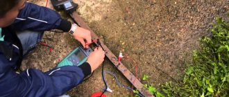
Continuity of supply wires
Very often, a device that has been in use for a long time and has been frequently used has a break in one of the cord wires. To do this, switching the multimeter to the audio test mode, touch one pin of the plug and the cord connected to the iron. If the sound signal does not sound, touch the probe to another wire of the cord connected to the iron. If both wires of the cord are intact and in both cases a sound signal is heard, we proceed to testing the heater itself, also in ohmmeter mode at a limit of 200 Ohms.
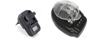
Low power power cord
If the cause of the breakdown is the cord, we replace the cord with a similar one, always (!) taking into account the power of the device. That is, for an iron or electric kettle you cannot use a cord with small cross-section wires, used to power, for example, a tape recorder. Such a wire will soon melt and fail.
Power cord designed for high power
Breakdowns also often occur in equipment power switches. If, for example, there is a table lamp with a power switch that “sticks” or turns on every once in a while, or the device has stopped turning on altogether, such a switch also needs to be checked and ringed with a multimeter in the audio test mode. To do this, install one multimeter probe on one terminal of the switch, the second probe on the other and click the switch.
In one of the two positions the tester beep should sound. To be completely sure that the switch is working, you can click it, ringing; when the switch is closed, there will be a sound signal, but when it opens, there will be no sound. This is done to check the mechanics of the switch. Sometimes the contacts of such switches burn out, in this case, if the switch is an open type, you can wipe the contacts with a cotton swab and alcohol, or if the soot is strong, carefully clean them with a knife.
In the same way, setting the multimeter to the audio continuity mode, check any fuses (fuse links) by touching both terminals with probes. If at the same time a sound signal is heard, then the fuse is intact and can be installed in the device; if there is no sound signal, then the fuse is blown. Of course, fuses should not be replaced with the first ones available, but only with ones designed for the same current.
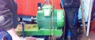
Electric DC motor
There may be a need to check the motor before turning it on, for example, like the one shown in the photo above; such motors are found, for example, in household hair dryers. The winding of such a motor can be tested with a multimeter in ohmmeter mode, setting it to a limit of 200 Ohms. In principle, in this way you can ring the winding of any motor by connecting the probes of a multimeter to the beginning and end of the winding.
How to fix a soldering iron with a regulator yourself?
Such electrical devices are equipped with a special device for adjusting the temperature of the tip. Using this soldering iron is quite convenient. The master knows that it is heating up thanks to the LED, which glows while the tip is heating. When the working surface reaches the desired temperature, the LED will go out, after which you can begin soldering. According to reviews from owners of such soldering irons, these power tools often fail. For example, there are times when buttons come off or an LED does not light up. Some home craftsmen wrap buttons with insulating tape. To repair the device, you must first carefully disassemble it. When you do this, you will see the op amp. It is a microcircuit in which, most likely, one of the small batteries has become disconnected. It needs to be reattached. For this purpose, you first need to clean the “legs” of the battery, tin them, and then solder them in their original place. After completing these steps, the soldering iron can be assembled and tested.
Types of soldering equipment
There are several different types of tools for performing the soldering process. The most common types of devices are the following:
- instruments equipped with a nichrome heater;
- tool with ceramic heater;
- devices with induction heater;
- instrument with pulse heater;
- gas tools;
- battery powered devices;
- hot air and infrared soldering installations.
A soldering iron with a ceramic heater heats up faster.
Devices with heaters made of nichrome wire operate by passing alternating or direct current. This type of soldering iron usually does not have heat controls. The exception is a small number of models equipped with sensors to control heating. A thermocouple is used as a temperature sensor.
A tool with a ceramic heater is distinguished by the fact that heating is carried out by supplying power to the contacts of the heater, made of conductive special ceramics. Such devices are more modern and have a number of advantages, the main ones being the heating rate of the working element of the device and a long service life. In addition to this, devices with a ceramic heating element are equipped with temperature and power regulators, which have a wide range of adjustments.
Induction devices differ in that an inductor coil is used to heat the tool. The tip of the device has a ferromagnetic coating, in which the coil creates a magnetic field with an induced current. The tip is heated due to the action of currents induced in the magnetic field. By changing the properties of the ferromagnetic coating, the degree of heating of the device tip is adjusted.
Pulse soldering irons are a category of tools whose tip is heated by exposing it to a short current pulse after pressing the start button. These devices are characterized by particularly rapid heating of the tool tip.
Hot air and infrared soldering stations are specific equipment that is used only by specialists.