2.4. INSTRUCTIONS FOR USE AND TESTING OF PROTECTION MEANS USED IN ELECTRICAL INSTALLATIONS
2.4. Voltage indicators
Purpose
2.4.1. Voltage indicators are designed to determine the presence or absence of voltage on live parts of electrical installations.
2.4.2. General technical requirements for voltage indicators are set out in the state standard.
Voltage indicators above 1000 V
Operating principle and design
2.4.3. Voltage indicators above 1000 V react to capacitive current flowing through the indicator when its working part is introduced into the electric field formed by live parts of electrical installations that are energized, and the “ground” and grounded structures of electrical installations.
2.4.4. The indicators must contain the main parts: working, indicator, insulating, and also a handle.
2.4.5. The working part contains elements that react to the presence of voltage on the controlled current-carrying parts.
The housings of the working parts of voltage indicators up to 20 kV inclusive must be made of electrical insulating materials with stable dielectric characteristics. The housings of the working parts of voltage indicators of 35 kV and above can be made of metal.
The working part may contain an electrode tip for direct contact with the controlled current-carrying parts and not contain an electrode tip (non-contact type indicators).
The indicator part, which can be combined with the working part, contains elements of light or combined (light and sound) indication. Gas-discharge lamps, LEDs or other indicators can be used as light indication elements. Light and sound signals must be reliably recognizable. The audio signal should have a frequency of 1 - 4 kHz and a chopping frequency of 2 - 4 Hz when indicating phase voltage. The sound signal level must be at least 70 dB at a distance of 1 m along the axis of the sound emitter.
The working part may also contain a body for its own serviceability monitoring. Control can be carried out by pressing a button or be automatic by periodically sending special control signals. In this case, it must be possible to fully check the serviceability of the electrical circuits of the working and indicator parts.
Working parts must not contain switching elements intended for turning on power or switching ranges.
2.4.6. The insulating part of the signs must be made of the materials specified in clause 2.1.2.
The insulating part can be composed of several links. To connect the links to each other, parts made of metal or insulating material can be used. It is permissible to use a telescopic design, but spontaneous folding must be prevented.
2.4.7. The handle can be one piece with the insulating part or be a separate link.
2.4.8. The design and weight of the signs must ensure that one person can operate them.
2.4.9. The electrical circuit and design of the indicator must ensure its operability without grounding the working part of the indicator, including when checking the absence of voltage, carried out from telescopic towers or from wooden and reinforced concrete supports of 6 - 10 kV overhead lines.
2.4.10. The minimum dimensions of the insulating parts and handles of voltage indicators above 1000 V are given in table. 2.4.
Table 2.4
MINIMUM DIMENSIONS OF INSULATING PARTS AND HANDLES FOR VOLTAGE INDICATORS ABOVE 1000 V
┌─────────────────────────┬────────────── ───────── ───────────────┐ │ Rated voltage │ Length, mm │ │ electrical installations, kV ├───────────── ──────┬─ ─────────────────┤ │ │ insulating part │ handle │ ├────────────── ────────── ─┼───────────────────┼──────────────────┤ │From 1 to 10 │ 230 │ 110 │ │More │ └────────────── ───────────┴───────────────────┴───────── ───────── ┘
2.4.11. The voltage indicator indication voltage should be no more than 25% of the rated voltage of the electrical installation.
For indicators without a built-in power supply with a pulse signal, the indication voltage is the voltage at which the signal interruption frequency is at least 0.7 Hz.
For indicators with a built-in power supply with a pulse signal, the indication voltage is the voltage at which the signal interruption frequency is at least 1 Hz.
For other indicators, the indication voltage is the voltage at which there are distinct light (light and sound) signals.
2.4.12. The time for the first signal to appear after touching a live part under voltage equal to 90% of the rated phase voltage should not exceed 1.5 s.
2.4.13. The working part of the indicator for a certain voltage should not respond to the influence of neighboring circuits of the same voltage, spaced from the working part at the distances indicated in the table. 2.5.
Table 2.5
DISTANCE TO THE CLOSEST WIRE OF THE NEIGHBORING CIRCUIT
┌─────────────────────────┬────────────── ───────── ───────────────┐ │ Rated voltage │Distance from the indicator to the nearest │ │ electrical installation, kV │ wires of the adjacent circuit, mm │ ├────── ────── ─────────────┼─────────────────────────── ───────── ──┤ │Above 1 to 6 │ 150 │ │Above 6 to 10 │ 220 │ │Above 10 to 35 │ 500 │ │110 │ 1500 │ │150 │ 1800 │ │220 │ 2500 │ └─────── ──────────────────┴────────────────────── ───────── ───────┘
Performance tests
2.4.14. During operation, mechanical tests of voltage indicators are not carried out.
2.4.15. Electrical tests of voltage indicators consist of testing the insulating part with increased voltage and determining the indication voltage.
Testing of the working part of voltage indicators up to 35 kV is carried out for indicators of this design, during operations with which the working part can cause a phase-to-phase short circuit or a phase-to-ground fault. The need to test the insulation of the working part is determined by the operating manuals.
For voltage indicators with a built-in power source, its condition is monitored and, if necessary, the batteries are recharged or the batteries are replaced.
2.4.16. When testing the insulation of the working part, voltage is applied between the tip electrode and the screw connector. If the indicator does not have a screw connector electrically connected to the indication elements, then an auxiliary electrode for connecting the test installation wire is installed at the boundary of the working part.
2.4.17. When testing the insulating part, voltage is applied between the element of its articulation with the working part (threaded element, connector, etc.) and a temporary electrode placed at the restrictive ring on the side of the insulating part.
2.4.18. The indication voltage of indicators with a gas-discharge indicator lamp is determined according to the same scheme by which the insulation of the working part is tested (clause 2.4.16).
When determining the indication voltage of other indicators that have an electrode tip, it is connected to the high-voltage terminal of the testing installation. When determining the indication voltage of indicators without a tip electrode, it is necessary to touch the end side of the working part (head) of the indicator to the high-voltage terminal of the test installation.
In both of the latter cases, the auxiliary electrode is not installed on the pointer and the grounding terminal of the test setup is not connected.
The voltage of the test installation smoothly rises from zero to the value at which the light signals begin to meet the requirements of clause 2.4.11.
2.4.19. The standards and frequency of electrical tests of indicators are given in Appendix 7.
Terms of use
2.4.20. Before you start working with the pointer, you need to check its serviceability.
The serviceability of indicators that do not have a built-in monitoring device is checked using special devices, which are small-sized sources of increased voltage, or by briefly touching the electrode-tip of the indicator to live parts that are known to be energized.
The serviceability of indicators with a built-in control unit is checked in accordance with the operating manuals.
2.4.21. When checking the absence of voltage, the time of direct contact of the working part of the indicator with the controlled current-carrying part must be at least 5 s (in the absence of a signal).
It should be remembered that although some types of voltage indicators can signal the presence of voltage at a distance from live parts, direct contact with them by the working part of the indicator is mandatory.
2.4.22. In electrical installations with voltages above 1000 V, the voltage indicator should be used with dielectric gloves.
Voltage indicators up to 1000 V
Purpose, principle of operation and design
2.4.23. General technical requirements for voltage indicators up to 1000 V are set out in the state standard.
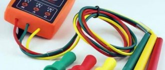
2.4.24. In electrical installations with voltages up to 1000 V, two types of indicators are used: double-pole and single-pole.
Bipolar indicators that operate when active current flows are designed for electrical installations of alternating and direct current.
Single-pole indicators operating when capacitive current flows are intended for electrical installations with alternating current only.
The use of two-pole indicators is preferable.
The use of test lamps to check the absence of voltage is not allowed.
2.4.25. Bipolar indicators consist of two housings made of electrical insulating material, containing elements that react to the presence of voltage on the controlled live parts, and elements of light and (or) sound indication. The housings are connected to each other by a flexible wire at least 1 m long. At the points of entry into the housings, the connecting wire must have shock-absorbing bushings or thickened insulation.
Case sizes are not standardized and are determined by ease of use.
Each body of a two-pole indicator must have a rigidly fixed tip electrode, the length of the non-insulated part of which should not exceed 7 mm, except for indicators for overhead lines, in which the length of the non-insulated part of the tip electrodes is determined by technical conditions.
2.4.26. A single-pole indicator has one housing made of electrical insulating material, which houses all elements of the indicator. In addition to the electrode tip that meets the requirements of clause 2.4.25, there must be an electrode on the end or side of the housing for contact with the operator’s hand.
The dimensions of the case are not standardized; they are determined by ease of use.
2.4.27. The indication voltage of the indicators should be no more than 50 V.
Indication of the presence of voltage can be stepped, supplied in the form of a digital signal, etc.
Light and sound signals may be continuous or intermittent and must be reliably recognizable.
For indicators with a pulse signal, the indication voltage is the voltage at which the interval between pulses does not exceed 1.0 s.
2.4.28. Voltage indicators up to 1000 V can also perform additional functions: checking the integrity of electrical circuits, identifying phase wires, determining polarity in DC circuits, etc. In this case, the pointers should not contain switching elements intended for switching operating modes.
Expanding the functionality of the indicator should not reduce the safety of operations to determine the presence or absence of voltage.
Performance tests
2.4.29. Electrical tests of voltage indicators up to 1000 V consist of testing the insulation, determining the indication voltage, checking the operation of the indicator at an increased test voltage, checking the current flowing through the indicator at the highest operating voltage of the indicator.
If necessary, the indication voltage in DC circuits is also checked, as well as the correct polarity indication.
The voltage gradually increases from zero, while the values of the indication voltage and the current flowing through the indicator at the highest operating voltage of the indicator are recorded, after which the indicator is turned on for 1 minute. maintained at an increased test voltage, exceeding the highest operating voltage of the pointer by 10%.
2.4.30. When testing indicators (except for insulation tests), the voltage from the test installation is applied between the tip electrodes (for double-pole indicators) or between the tip electrode and the electrode on the end or side of the housing (for single-pole indicators).
2.4.31. When testing the insulation of two-pole indicators, both housings are wrapped in foil, and the connecting wire is lowered into a vessel with water at a temperature of (25 +/- 15) °C so that the water covers the wire, not reaching the handles of the housings by 8 - 12 mm. One wire from the testing installation is connected to the electrode tips, the second, grounded, is connected to the foil and lowered into water (scheme version - Fig. 2.1).
———————————
Here and below, drawings are not shown.
For single-pole indicators, the body is wrapped in foil along the entire length to the limiting stop. A gap of at least 10 mm is left between the foil and the contact on the end (side) part of the housing. One wire from the test setup is connected to the tip electrode, the other to the foil.
2.4.32. The standards and frequency of operational tests of indicators are given in Appendix 7.
Terms of use
2.4.33. Before starting to work with the pointer, it is necessary to check its serviceability by briefly touching live parts that are known to be energized.
2.4.34. When checking the absence of voltage, the time of direct contact of the pointer with the controlled live parts must be at least 5 s.
2.4.35. When using single-pole indicators, contact must be ensured between the electrode on the end (side) part of the housing and the operator’s hand. The use of dielectric gloves is not allowed.
Requirements for pointers
The general list of requirements for the use of UN includes compliance with the stated technical characteristics according to GOST, verification, which includes visual inspection, resistance to mechanical and climatic influences, electrical insulation resistance, accurate operation of the charger, compliance with working drawings, presence of roughness, complete set of all components (especially the restrictive ring), the presence of a certificate and accompanying documents (diagrams, instructions, memos, etc.).
Visual inspection consists of inspecting and checking serviceability, completeness, integrity of packaging, presence of markings and corrosion protection. Compliance with the working drawing is carried out using measuring tools. The surface is checked for the presence of roughness using an optical indicator or profilometer. If the product body is made of metal, then it must be made in accordance with GOST 9.302.
Also read: What is a reduced transformer
The unit must be in good working order, without external damage, with working light and sound signals, and the insulating parts must have dielectric properties. The current value must be indicated in the technical data sheet. Only if such requirements are met is the device permitted to be used.
IMPORTANT! All UN have a production test report and a safety certificate issued by the authorized bodies of the Russian Federation. The tested device has a tag with a stamp with the verification date.
Individual voltage indicator.
To warn personnel about the presence of voltage when approaching the wires of 6-10 kV overhead lines and live parts of the switchgear at an unacceptable distance, an individual voltage alarm of the SNI6-10 type has been developed and manufactured by industry. The signaling device is an additional means of protection. The sensitivity of the alarm ensures that it operates at a distance of at least 1.4 m from the nearest wire at a line voltage of 6 kV. The alarm emits an intermittent sound signal at intervals of 2.5-5 times per second. Sound signal frequency 500-2500 Hz. The alarm is powered by a block of sealed batteries with a voltage of 4.8 V, which ensure continuous operation for 5 hours. The alarm is equipped with a battery charger and a serviceability check button, by pressing which the serviceability of the alarm is checked before use. Overall dimensions of the signaling device 100X70X40 mm, weight 200 g.
- Back
- Forward