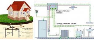
The article will discuss the grounding of cable-supporting structures, we will consider standard solutions, as well as documents and regulations governing this issue.
The main documents defining the rules that are mandatory when using metal trays as passive protection or a grounding conductor are:
In addition to these mandatory documents, there are specifications and certificates of conformity, technical passports issued by manufacturers of metal trays. They provide a description, technical parameters of the products and indicate the scope of application.
Basic requirements for grounding cable-supporting structures
Possibility of use: “Metal boxes and trays of electrical wiring can be used as protective conductors, provided that the design of the boxes and trays allows such use, and there is a direct indication of this in the manufacturer’s documentation, and their location excludes the possibility of mechanical damage...” (PUE p. 1.7.121)
In both cases, there is a screw connection, which is permissible in the grounding, grounding or potential equalization circuit in rooms with a non-aggressive environment or in outdoor electrical installations. In this case, the requirements of GOST 10434 “Electrical contact connections” must be met. General technical requirements" for class 2 connections. (PUE pp1.7.139;1.7.142).
There are some restrictions on the use of metal trays as a grounding conductor:
Conditions for using trays as grounding.
When planning to use a cable support system as a grounding conductor, you must remember the following:
— specially designed conductors are used (multi-core cable cores; insulated or non-insulated wires in a common sheath with phase wires; permanently laid insulated or non-insulated conductors);
- secondly - open conductive parts of electrical installations (aluminum cable sheaths; steel pipes of electrical wiring; metal sheaths and supporting structures of busbars and complete prefabricated devices).
— and only in the absence of all the listed possibilities, metal boxes and trays of electrical wiring are used (PUE clauses 1.7.121; 1.7.122).
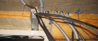
Metal trays produced by JSC DKS
For grounding trays or galvanic connection, the following are offered:
Possible cross-sectional area of the grounding conductor is from 7.0 mm kV to 78.5 mm kV (conductor diameter from 3 mm to 10 mm)
Possible cross-sectional area of the grounding conductor is from 0.8 mm kV to 78.5 mm kV (conductor diameter from 1 mm to 10 mm).
— Connecting metal trays to each other with a flexible stranded wire of the appropriate cross-section, crimped on both sides with Quatro lugs. Grounding is secured using hardware from the Combitech system.
Expert opinion
It-Technology, Electrical power and electronics specialist
Ask questions to the “Specialist for modernization of energy generation systems”
Grounding of cable-supporting structures It is additionally worth noting that according to the PUE, the use of metal hoses in hidden wiring of combustible structures is not allowed. Ask, I'm in touch!
Metal sleeve Types of execution and application.
Depending on the type of lock (P1 - P6), the metal hose is divided according to the method of operation. Type P3 (“er three”) is designed to protect wires, cables, etc. from mechanical damage.
“Oil and petrol resistant, frost resistant” - UHL1, -550C to +600C;
The most common question related to a metal hose is whether it needs to be grounded. According to PUE clause 1.7.76:
“The requirements for protection from indirect contact apply to:
5) metal shells and armor of control and power cables and wires for voltages not exceeding those specified in 1.7.53, laid on common metal structures, including in common pipes, boxes, trays, etc., with cables and wires on higher voltages."
Connections must be protected from corrosion and mechanical damage.
For bolted connections, provisions must be made to prevent contact loosening.”
MRPI has the necessary dielectric properties, which is confirmed by test report No. 085-07/10-ST.
Additionally, it is worth noting that according to the PUE, the use of metal hoses in hidden wiring of combustible structures is not allowed.
In conclusion, we can conclude that a metal hose is a universal means for protecting a cable line, depending on operating conditions and type of execution, in industrial and civil construction projects.
Expert opinion
It-Technology, Electrical power and electronics specialist
Ask questions to the “Specialist for modernization of energy generation systems”
Grounding a metal hose in PVC insulation To protect people from electric shock when the insulation is damaged, at least one of the following protective measures must be applied: grounding, grounding, protective shutdown, isolation transformer, low voltage, double insulation, potential equalization. Ask, I'm in touch!
Self-production
After preparing all the necessary materials and choosing a suitable place for arranging the grounding, you can proceed to the direct operations of assembling the grounding loop. At the preparatory stage, pipe or other profile sections are cut, the size of which is chosen to be 20-30 cm larger than the calculated one (this is necessary to compensate for the bending of the top of the workpiece when it is driven into the ground).
Simultaneously with the preparation of point pin grounding conductors, the stage of excavation begins, consisting of the preparation of grooves with beveled edges (to better retain the soil from shedding).
The order of operations performed during excavation work is as follows:
- First, the site for the future ground loop is prepared (cleared) and its markings are made;
- Then, using the already applied markings, grooves are dug with a depth of 70-80 cm and a width of about 50 cm (the depth is chosen to minimize corrosion of metal bonds);
- After this, the pins, cut to length, are driven in at the designated points so that about 20 cm protrude above the surface (see photo below);
Arrangement of a grounding loop
- Upon completion of the installation of all vertical elements, their upper parts are cut off, and the contact pads are thoroughly cleaned, after which metal connections are welded to them;
- After all welding seams have cooled, they are cleaned with a grinder and a grinding disc, and then painted with a special tar-based protective paint;
Note! Only areas of welded joints that are most susceptible to corrosion are painted.
- Next, from the short-circuit point closest to the residential building, a ditch is dug to the same depth that was dug under the metal connections (its width may be slightly smaller, since the connecting strip is made solid and does not require welding);
- Then a strip of metal with a standard size of at least 25x4 mm is laid in the prepared trench, which is subsequently welded to a pin or jumper (metal bond);
- At the final stage of work, near the wall of the house, the already laid metal strip is raised to a height of about 200 mm, where a busbar (wire) is connected to it by bolting or welding, going to the main distribution board (photo below).
Input of grounding into the house
To connect the finished grounding to the existing power supply circuit, you will need to familiarize yourself with the existing grounding schemes.
Entering the house
The circuit is connected to the grounding bus of the distribution system using a steel strip with a standard size of 24x4 mm or copper and flexible wire with a cross-section of 10 mm². In some cases, specifically specified in the PUE, it is allowed to use aluminum wire with a cross-section of 16 mm² for this purpose (see figure below).
Scheme of grounding installation in the panel
If there is a choice between the options proposed above, preference is given to copper wire, which has the most suitable characteristics for the task.
In the final part of the review, we draw the attention of users to the fact that it is not very easy to make a grounding loop with your own hands, since when carrying out this work, strict compliance with the requirements of the PUE is necessary. For those who are not completely confident in their abilities, there is always a “backup” way out - to invite representatives of an organization specializing in the manufacture of groundings
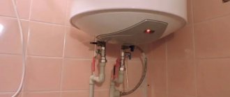
Cable laying in a metal hose
To protect wiring from exposure to dust, moisture, to protect from fire in the event of a short circuit, and from various mechanical damage when connecting electricity, a flexible metal pipe is used - a metal hose. It is very easy to install due to its large bending radius.
The metal hose is made of steel or galvanized tape, and all hoses have their own designations (markings). Marking RZ - for steel metal hoses, RZ-Ts for galvanized ones, sealed ones are marked with the abbreviation - RZTsP, hoses that have explosion protection are designated - VSG.
This product is used for laying electrical cables, as well as for computer network cables or communication cables.
Laying electrical cables in a metal sleeve
Grounding systems (GS)
According to the main provisions of the PUE, the grounding of electrical installations and working equipment can be organized in several ways, depending on the neutral connection circuit at the transformer substation.
Based on this feature, there are several types of grounding systems, designated in accordance with generally accepted rules. Their classification is based on a combination of the Latin symbols “T” and “N”, which means the transformer neutral grounded at the substation.
The letters “S” and “C” added to this designation are abbreviations from the English words “common” - common gasket and “select” - separate. They indicate the method of organizing the grounding conductor along the entire length of the supply line from the substation to the consumer (in the first case - a combined PEN, and in the second - separate PE and N).
Combined with a hyphen “CS” means that on some part of the route the grounding conductor is combined with the working “zero”, and on the remaining section they are laid separately.
Cable laying in a metal hose
To protect wiring from exposure to dust, moisture, to protect from fire in the event of a short circuit, and from various mechanical damage when connecting electricity, a flexible metal pipe is used - a metal hose. It is very easy to install due to its large bending radius.
The metal hose is made of steel or galvanized tape, and all hoses have their own designations (markings). Marking RZ - for steel metal hoses, RZ-Ts for galvanized ones, sealed ones are marked with the abbreviation - RZTsP, hoses that have explosion protection are designated - VSG.
This product is used for laying electrical cables, as well as for computer network cables or communication cables.
Laying electrical cables in a metal sleeve
Expert opinion
It-Technology, Electrical power and electronics specialist
Ask questions to the “Specialist for modernization of energy generation systems”
Metal hose for cable: laying the cable in a metal hose Since this method is not always available, in particular when laying the wiring yourself, it is worth resorting to the help of tight-fitting clamps. Ask, I'm in touch!
Characteristics you need to know when using metal corrugated pipes
- Inner diameter. May differ significantly from the outside: it depends on the shape of the profile. If you know the diameter of the outer sheath of the cable, you need to multiply this figure by 1.5 or 2. When laying two cables in a sleeve, the diameter is added up.
- Conditional pass. This is actually the minimum diameter of the coil profile, which is taken into account when selecting connecting and input couplings for corrugated pipes.
- Outer diameter - the maximum size of the coil wave, according to the outer coating (if any).
- The tightness class is either according to the “IP” standard system - international, or according to the domestic classification: P1, P2, P3. The higher the number, the worse the tightness and the lower the cost.
- The tightness depends on the material of the interturn seal. The conditions of use also depend on it. Cotton - internal installation in rooms with a non-aggressive environment. Asbestos - operation in fire hazardous conditions, or with local heating. Polypropylene - outdoor use, or rooms with direct exposure to liquids.
- Climate class. Indicated in the product passport. Must be taken into account when laying. There are quite a lot of varieties: about 50 options.
- Passage of interference both from inside the corrugation and inside the sleeve. The undisputed leader in this discipline is the accordion-type sleeve. But a helical corrugation can also serve as an excellent shield if it is grounded.
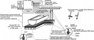
The main parameters and components of the metal hose in the illustration:
1. The main profile is a coil made of metal.
2. Sealing material sealing the interturn grooves.
3. Outer shell made of polyvinyl chloride.
D. Outer diameter - measured along the outer shell.
d. Conditional diameter (when selected according to the diameter of the cable to be laid - internal diameter).
Circuit design
Components
The previously mentioned grounding resistance (Rз) of the circuit is the main parameter controlled at all stages of its operation and determines the effectiveness of its use. This value must be so small as to provide a free path for the emergency current tending to flow into the ground.
Note! The most important factor that has a decisive influence on the value of grounding resistance is the quality and condition of the soil at the site of the installation. Based on this, the charger in question or the ground loop of the charge circuit (which in our case is the same thing) must have a design that meets the following requirements:
Based on this, the charger in question or the ground loop of the charge circuit (which in our case is the same thing) must have a design that meets the following requirements:
- It must include a set of metal rods or pins with a length of at least 2 meters and a diameter of 10 to 25 millimeters;
- They are connected to each other (necessarily for welding) by plates of the same metal into a structure of a certain shape, forming a so-called “grounding conductor”;
- In addition, the device includes a supply copper busbar (also called electrical) with a cross-section determined by the type of equipment being protected and the magnitude of the drain current (see the table in the figure below).
Table of busbar sections
These component devices are necessary to connect the elements of the protected equipment with the descent (copper busbar).
Differences in device location
According to the provisions of the PUE, the protective circuit can have both external and internal design, and each of them is subject to special requirements. The latter establishes not only the permissible resistance of the ground loop, but also stipulates the conditions for measuring this parameter in each particular case (outside and inside the object).
When dividing grounding systems according to their location, it should be remembered that only for external structures the question of how the grounding resistance is normalized is correct, since it is usually absent indoors. Internal structures are characterized by wiring of electrical busbars along the entire perimeter of the premises, to which grounded parts of equipment and devices are connected through flexible copper conductors.
For structural elements grounded outside the facility, the concept of re-grounding resistance is introduced, which appeared as a result of the special organization of protection at the substation. The fact is that when forming a neutral protective conductor or a working conductor combined with it at the supply station, the neutral point of the equipment (step-down transformer, in particular) is already grounded once.
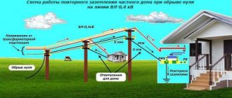
Therefore, when another local grounding is made at the opposite end of the same wire (usually a PEN or PE bus connected directly to the consumer panel), it can rightfully be called repeated. The organization of this type of protection is shown in the figure below.
Re-grounding
Important! The presence of local or repeated grounding allows you to insure yourself in case of damage to the protective neutral wire PEN (PE - in the TN-CS power supply system). Such a malfunction is usually found in technical literature under the name “zero burnout”
Such a malfunction is usually found in technical literature under the name “zero burnout.”
Smallest cross-sections of protective conductors
| Section of phase conductors, mm2 | Minimum cross-section of protective conductors, mm2 |
| S ≤ 16 16 S ≤ 35 S > 35 | S 16 S /2 |
It is allowed, if necessary, to take the cross-section of the protective conductor less than required if it is calculated according to the formula (only for shutdown time ≤ 5 s
):
where S
— cross-sectional area of the protective conductor, mm2
;
I
- short circuit current, providing the time to disconnect the damaged circuit by the protective device in accordance with Table. 1.7.1 and 1.7.2 or in no more than 5 s
in accordance with 1.7.79,
A
;
t
— response time of the protective device, s
;
k
— coefficient, the value of which depends on the material of the protective conductor, its insulation, initial and final temperatures. k value
for protective conductors under various conditions are given in table. 1.7.6-1.7.9.
If the calculation results in a cross section different from that given in table. 1.7.5, then you should select the nearest larger value, and when obtaining a non-standard cross-section, use conductors of the nearest larger standard cross-section.
The maximum temperature values when determining the cross-section of the protective conductor should not exceed the maximum permissible heating temperatures of the conductors during a short circuit
in accordance with Ch. 1.4, and for electrical installations in explosive areas must comply with GOST 22782.0 “Explosion-proof electrical equipment. General technical requirements and test methods".
1.7.127. In all cases, the cross-section of copper protective conductors that are not part of the cable or laid not in a common shell (pipe, box, on the same tray) with phase conductors must be no less than:
2,5 mm2
— with mechanical protection;
4 mm2
- in the absence of mechanical protection.
The cross-section of separately laid protective aluminum conductors must be at least 16 mm2
1.7.128. In the TN
To meet the requirements of 1.7.88, it is recommended that neutral protective conductors be laid together or in close proximity to phase conductors.
Table 1.7.6