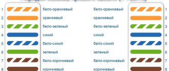
Standards for symbols
The procedure for indicating symbols on diagrams is regulated by GOST 21.614.88. This standard was published relatively recently. The new GOST replaced the old Soviet standard. According to the new rules, the signs on the diagrams must coincide with the regulated ones.
The inclusion of other equipment in the circuit must meet the requirements of GOST 2.721.74. This document establishes standards for general use signs. The procedure for organizing the circuit of input distribution devices is also regulated by GOST 2.721.74
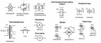
Designations are made in the form of graphic symbols, which are the simplest geometric objects, including squares, rectangles, circles, lines and points. In certain combinations, these graphic elements indicate certain components of electrical devices, machines and devices used in electrical engineering. In addition, the symbols represent the operating principles of the system.
Representation of electrical equipment on plans
Despite the fact that GOST 2.702-2011 and GOST 2.701-2008 take into account this type of electrical circuit as a “layout diagram” for the design of structures and buildings, one must be guided by the standards of GOST 21.210-2014, which indicate “SPDS.
Images on the plans of conventional graphic wiring and electrical equipment.” The document establishes UGO on plans for laying electrical networks of electrical equipment (lamps, switches, sockets, electrical panels, transformers), cable lines, busbars, tires.
The use of these symbols is used to draw up drawings of electric lighting, power electrical equipment, power supply and other plans. The use of these designations is also used in basic single-line diagrams of electrical panels.
The contours of all depicted devices, depending on the information richness and complexity of the configuration, are taken in accordance with GOST 2.302 on the scale of the drawing according to the actual dimensions.
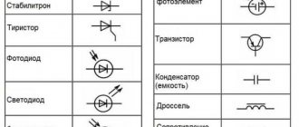
Conventional graphic symbols of switches, switches
On the pages of documentation GOST 21.210-2014 there is no separate designation for push-button switches, dimmers (dimmers). In some schemes, according to clause 4.7. the normative act uses arbitrary designations.
The updated version of GOST contains images of lamps with fluorescent and LED lamps.
Pointers on diagrams
Below is a graphic symbol that is usually used on working drawings.
Fittings are usually classified according to several criteria:
- degree of security;
- installation method;
- number of poles.
Due to different classification methods, there are differences among the symbols for connectors in the drawings.
Indicators on drawings for surface mounting
The receptacle symbols in the drawing below indicate the following characteristics.
- duality, single-pole and grounding;
- duality, single-pole and lack of grounding contact;
- single-pole, single-pole and protective contact;
- power socket with three poles and protection.
Signs for hidden installation
The picture below shows the following sockets:
- single with one pole and grounding;
- paired with one pole;
- power with three poles;
- single with one pole and without protective contact.
Symbols for waterproof sockets
The drawings use the following symbols for moisture-protected sockets:
- single with one pole;
- single with one pole and grounding device.
Socket and switch block indicators
To save space and also simplify the layout of electrical devices, they are often placed in a single block. In particular, this scheme allows you to save on gating. There may be one or more outlets nearby, as well as a switch.
The picture below shows a socket and a switch with one key.
Symbols for switches on diagrams
All switches on electrical diagrams are shown like this:
Switch indicators with one and two keys
The picture below shows the following switches:
Below is a table showing the symbols of the fittings.
The table shows the wide range of possible devices. However, the industry produces more and more new designs, so it often happens that new fittings have already appeared, but the symbols for them are still missing.
There are three main types of socket designation: plug-in, numbered one, plug-in and surface-mount sockets with a contact for grounding - numbered two and three, respectively.
Read also: Hydro splitter with gasoline engine
What these images have in common is a semicircle with an incoming central line. This semicircle can be completely painted black, and also have many incoming lines showing the number of stripes, protective contacts, and switches. More details in the attached table with symbols that correspond to GOST.
A socket with two poles (phase + neutral) without grounding, overhead or open installation - a semicircle lying on the cut, with one vertical strip on top, if there are two strips, then the socket is double.
A socket with two poles (phase + zero) with grounding, overhead or open installation - a semicircle lying on the cut, on top there is one horizontal strip lying on the semicircle and one vertical strip extending from it, if two more strips extend from the corners, then the socket is three-pole, t .e. at 380 Volts.
A socket with two poles (phase + neutral) without grounding, built-in or hidden installation - a semicircle cut by one line lying on the cut, one vertical strip on top, if there are two strips, then the socket is double.
Socket with two poles (phase + neutral) with grounding, built-in or hidden installation - a semicircle cut by one line lying on the cut, on top there is one horizontal strip lying on the semicircle and one vertical strip extending from it, if two more strips extend from the corners, then the socket three-pole, i.e. at 380 Volts.
A socket with two poles (phase + neutral) with grounding, built-in or hidden installation - a semicircle cut by one line lying on the cut, on top there is one horizontal strip lying on the semicircle and two vertical strips extending from it.
A socket with two poles (phase + zero) with grounding, overhead or open installation - a filled semicircle lying on the section, on top there is one horizontal strip lying on the semicircle and one vertical strip extending from it, if without a horizontal strip, then the socket is without grounding.
If the socket is located in the same block as the switches, then an icon in the shape of the letter “T” is attached to them.
We have already talked many times about how important it is to correctly draw up a power supply diagram before carrying out home electrical repairs; everything should start with it. The diagrams show the main electrical components - the input line, the electric energy meter, protection devices, distribution boxes and conductors extending from them, switching devices, lighting elements. In order to look at the diagram at least to understand it a little, you need to know what the symbols of switches and sockets are in the drawings. We suggest you learn a little about this.
Many people begin renovation work in a house under construction or a newly purchased apartment by inviting a specialist to help draw up a diagram. All you need to do is tell us in detail where you plan to place large-sized furniture and household electrical appliances. And the task of a professional is to schematically display all this, indicating the installation location of switches and sockets on the plan. Such a drawing will help you clearly determine the amount of materials needed and rationally plan the procedure for carrying out electrical installation work.
Read also: What to make rivets from
We will not talk about complex electrical elements, such as switches, relays, thyristors, triacs, motors. This is not necessary for home electrical networks. Our main task is to learn to recognize the designation of household switches and sockets on schematic drawings.
The designation of electrical elements is carried out using graphic symbols - triangles, circles, rectangles, lines, etc.
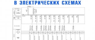
Images of wiring lines and conductors
Table 1
| Name | Image | Size, mm |
| 1. Wiring line | ||
| General image It is allowed to indicate wiring data (type of current, voltage, material, installation method, wiring mark, etc.) above the line image. | Thickness 1.0 | |
| For example. 110V DC circuit | Same | |
| It is allowed to indicate the number of conductors in a line with serifs. | ||
| For example. Line consisting of three conductors | ||
| 1.1. Control line | ||
| 1.2. Emergency evacuation and security lighting network line | ||
| 1.3. Voltage line 36V and below | ||
| 1.4. Grounding and grounding line | ||
| 1.5. Grounding switches | ||
| 1.6. Metal structures used as grounding and grounding lines | ||
| 2. Laying wires and cables | ||
| 2.1. Open laying of one conductor | ||
| 2.2. Open routing of multiple conductors | ||
| 2.3. Open laying of one conductor under the ceiling | ||
| 2.4. Open laying of several conductors under the ceiling | ||
| 2.5. Laying on the cable and its end fastening | ||
| 2.6. Wiring in the tray | ||
| 2.7. Wiring in a box | ||
| 2.8. Wiring under the baseboard | ||
| 2.9. Cable end | ||
| 3. Vertical wiring | ||
| 3.1. Posting goes to a higher level or comes from a higher level | ||
| 3.2. The posting goes to a lower level or comes from a lower level | ||
| 3.3. The wiring crosses the mark shown on the plan from top to bottom or bottom to top and has no horizontal sections within this plan | ||
| 4. Wiring in pipes General image | ||
| 4.1. Wiring in a pipe laid openly | ||
| 4.2. Wiring in pipes laid openly | ||
| 4.3. The same, if it is necessary to display the dimensions of a group of pipes | ||
| 4.4. Wiring in a pipe laid under the ceiling, platform, indicating the location mark | ||
| 4.5. Wiring in pipes laid under the ceiling | ||
| 4.6. The same, if it is necessary to display the dimensions of a group of pipes | ||
| 4.7. Wiring in a pipe laid hidden (in concrete, in soil, etc.), indicating the location mark | ||
| 4.8. Wiring in hidden pipes | ||
| 4.9. The same, if it is necessary to display the dimensions of a group of pipes | ||
| 4.10. Wiring in a pipe laid from the route mark upwards | ||
| 4.11. Same thing, down | ||
| 4.12. The end of the wiring in the pipe | ||
| 4.13. Wiring in a pipe through the wall | ||
| 4.14. The same, through the ceiling | ||
| 4.15. Separating seal in pipes for hazardous areas | ||
| 4.16. Flexible wiring in a metal hose, flexible input | ||
| 5. Laying busbars and busbars | ||
| General image | Thickness 2.0 | |
| 5.1. Busbar laid on insulators | ||
| 5.2. Package of tires laid on insulators | Thickness 1.0 | |
| 5.3. Busbars or busbar trunking on racks | ||
| 5.4. The same, on suspensions | Same | |
| 5.5. The same, on the brackets | ||
| 5.6. Trolley line | ||
| 5.7. Trolley line sectioning | ||
| 5.8. Tire compensator, trolley |
Note. The image of the mounting location of the busbar according to clauses 5.1-5.5 must correspond to its design position.
6. Images of boxes, panels, equipment boxes, cabinets, panels, consoles are given in Table 2
Designation of sockets
A socket is a switching device that is part of a plug connection, works in tandem with a plug, and is designed to connect electrical appliances to the network.
The designation of sockets in the drawings is done in a semicircle, from the convex part of which one or more lines extend, depending on the type of switching device.
The video shows the main symbols of electrical equipment:
Sockets according to the installation method are:
- External (for open wiring). They are mounted on a wall surface. They are indicated by an empty semicircle that does not have any additional lines inside.
- Internal (for hidden wiring). They are mounted inside the wall; to do this, you need to make a hole and insert a special socket into it, reminiscent of a shallow glass in shape. In the schematic representation of such switching devices, the semicircle inside has a line in the center.
Double sockets are often used in household networks. They are a monoblock in which there are two plug connectors (that is, you can connect two plugs from two different electrical appliances) and one installation location (installation is carried out in one socket box). The designation of a double socket on the electrical diagram looks like a semicircle with two lines on the outer convex side:
In modern household networks, sockets with grounding are increasingly used; they guarantee long-term reliable operation of electrical appliances and the safety of people in terms of electric shock.
These devices differ from ordinary ones in that they have a third contact to which the ground wire is connected.
This wire goes to the general distribution panel, where it is connected to a special ground terminal. The designation of such an outlet on the electrical diagram is as follows:
As you can see, grounding is indicated by a horizontal line, which is tangentially adjacent to the convex part of the semicircle.
It is no longer uncommon for a modern home to be supplied not with a single-phase electrical network, but with a three-phase one. Some electricity consumers require a voltage of 380 V (heating boilers, water heaters, electric stoves). To connect them, three-pole sockets with protective grounding are used. Switching devices of this type have five contacts - three phase, one neutral and one more for protective grounding. A three-pole socket is indicated with three lines on the outside of the semicircle:
And this is what the symbols for double sockets with protective grounding look like:
Sometimes you can see the designation of a socket, in which the semicircle inside is completely painted in black. This means that the switching device is moisture-resistant; it is equipped with a protective cover that prevents moisture or dust from entering the socket. The degree of protection of such elements is marked with special symbols:
- The two English letters IP denote the very concept that the outlet has a certain level of protection.
- Then follow two numbers, the first of which indicates the degree of protection from dust, the second - from moisture.
Read also: Making a square-faced hammer
In the diagram, sockets with degree of protection IP 44-55 look like this:
If they have a protective grounding contact, then another horizontal line is added accordingly:
If you make a wiring diagram in specialized programs, then the video shows an example of a drawing in AutoCad:
Switch designation
A switch is a switching device designed to control lighting fixtures in the house. When it is turned on and off, the electrical circuit is closed or opened. Accordingly, when the switch is turned on, voltage is supplied to the lamp through a closed circuit, and it lights up. Conversely, if the switch is turned off, the electrical circuit is broken, the voltage does not reach the light bulb, and it does not light.
The designation of switches in the drawings is made by a circle with a dash at the top:
As you can see, the dash also has a small hook at the end. This means that the switching device is single-key. The designation of a two-key and three-key switch will have two and three hooks, respectively:
Similar to sockets, switches can be external or internal. All of the above designations refer to devices for open (or outdoor) installation, that is, when they are mounted on a wall surface.
The hidden (or internal) installation switch in the diagram is indicated in exactly the same way, only with hooks directed in both directions:
Switches intended for installation outdoors or in rooms with high humidity have a certain degree of protection, which is marked in the same way as sockets - IP 44-55. In the diagrams, such switches are depicted with a circle filled in black inside:
Sometimes you can see on the diagram an image of a switch, in which the lines with hooks from the circle are directed in two opposite directions, as if in a mirror image. This is how a switch is designated, or, as it is otherwise called, a pass-through switch.
These switching devices are connected according to a special circuit and make it possible to control the same lighting device from different places (their use is very convenient in long corridors, on flights of stairs).
They also come in two-key or three-key types: