Application area. Definitions
7.1.1.
This chapter of the Rules applies to electrical installations of: residential buildings listed in SNiP 2.08.01-89 “Residential Buildings”; public buildings listed in SNiP 2.08.02-89 “Public buildings and structures” (except for buildings and premises listed in Chapter 7.2): administrative and domestic buildings listed in SNiP 2.09.04-87 “Administrative and domestic buildings” ; Additional requirements may apply to electrical installations of unique and other special buildings not included in the above list. Further in the text, unless otherwise specified, the word “buildings” means all types of buildings to which this chapter applies.
The requirements of this chapter do not apply to special electrical installations in medical institutions, organizations and institutions of science and scientific services, to dispatch and communication systems, as well as to electrical installations, which by their nature should be classified as electrical installations of industrial enterprises (workshops, boiler rooms, thermal points, pumping stations, laundry factories, dry cleaning factories, etc.).
7.1.2. Electrical installations of buildings, in addition to the requirements of this chapter, must meet the requirements of the chapters of Section. 1-6 PUE to the extent that they are not changed by this chapter.
7.1.3. Input device (ID) is a set of structures, devices and instruments installed at the input of the supply line into the building or its separate part.
The input device, which also includes devices and devices of outgoing lines, is called an input distribution device (IDU).
7.1.4. The main distribution board (MSB) is a distribution board through which the entire building or its separate part is supplied with electricity. The role of the main switchboard can be performed by an ASU or a low voltage switchboard of a substation.
7.1.5. Distribution point (DP) is a device in which protection devices and switching devices (or only protection devices) are installed for individual electrical receivers or their groups (electric motors, group panels).
7.1.6. A group panel is a device in which protection devices and switching devices (or only protection devices) are installed for separate groups of lamps, plug sockets and stationary electrical receivers.
7.1.7. Apartment panel - a group panel installed in an apartment and designed to connect the network that supplies lamps, plug sockets and stationary electrical receivers of the apartment.
7.1.8. Floor distribution panel is a panel installed on the floors of residential buildings and intended to supply power to apartments or apartment panels.
7.1.9. Electrical room - room. accessible only to qualified service personnel, in which VU, ASU, main switchboard and other distribution devices are installed.
7.1.10. Supply network - a network from a substation switchgear or a branch from overhead power lines to the VU, ASU, main switchboard.
7.1.11. Distribution network - a network from the VU, ASU, main switchboard to distribution points and switchboards.
7.1.12. Group network - a network from panels and distribution points to lamps, plug sockets and other electrical receivers.
The height of the shield in the apartment: requirements and standards
The installation height of the distribution board in the apartment is regulated by the requirements of the PUE, clause 4.1.14, which determine the distance from the floor level in the range of 1.0-1.8 m from the floor; as an exception, the board can be placed at a height of 0.5-1.3 m in premises where elderly or disabled people live.
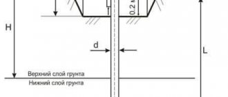
When placed on a power line support, from which a branch is made to the house, standards are provided for the installation of electrical panels at a height of 1.5 m from the floor. On such a support a board is placed with an input machine, an meter and the required electrical devices.
For manual operational control devices (switches, buttons), it is recommended that the installation height of electrical panels PUE be at the level of 0.7-1.9 m from the floor level.
When replacing a meter and ensuring its safe operation, PUE 1.5.36 provides for a distance from the switching device to the meter of no more than 10 meters . With a smaller distance from the support to the house, it is possible to install the input panel on the support, and place the meter on the facade of the house. The rules prohibit placing electrical devices and installations in bathtubs and showers, toilets, in closets and dressing rooms, above heating appliances and stoves, in damp rooms, balconies and loggias, in ventilation shafts.
Maintaining the height of the shield in the apartment is a guarantee of safety
The process of installing an electrical panel in an apartment is regulated by design documentation, the choice of equipment and the height of the electrical panel in the apartment. Compliance with these requirements allows, specializing in the production, assembly and installation of electrical panels, to guarantee the quality of the work performed and the safety of further operation of the products.
Work on installation and assembly of the electrical panel is carried out in accordance with the requirements of standards and PUE; they can be divided into two stages:
- preparatory – the completeness of the switchboard elements is checked, the installation height of the switchboard is determined, and cable products are prepared for connection;
- main - a switch is installed, an input circuit breaker is installed, neutral wires are connected, an electric meter, linear circuit breakers, RCDs are installed for groups of equipment or in rooms with high humidity, wires from load cables are connected;
- After assembling the panel, the meter terminal blocks are sealed by a representative of the energy supply organization.
Manufacturing and assembly of products is carried out in compliance with the installation standards for electrical panels. To place an order in St. Petersburg and Leningrad Region, we suggest calling +7 (981) 785-86-88 or writing by email
General requirements. Electricity supply
7.1.13. Electrical receivers must be powered from a 380/220 V network with a TN-S or TN-CS grounding system.
When reconstructing residential and public buildings with a network voltage of 220/127 V or 3 x 220 V, the network should be switched to a voltage of 380/220 V with a TN-S or TN-CS grounding system.
7.1.14. External power supply to buildings must meet the requirements of Chapter 1.2.
7.1.15. In dormitories of various institutions, in schools and other educational institutions, etc. the construction of built-in and attached substations is not allowed.
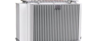
In residential buildings, in exceptional cases, it is allowed to place built-in and attached substations using dry-type transformers in agreement with state supervisory authorities, while sanitary requirements for limiting noise and vibration levels must be fully met in accordance with current standards.
The construction and placement of built-in, attached and free-standing substations must be carried out in accordance with the requirements of the chapters of Section. 4.
7.1.16. It is recommended that power and lighting electrical receivers be powered from the same transformers.
7.1.17. The location and layout of transformer substations must provide for the possibility of round-the-clock unhindered access to them for personnel of the energy supply organization.
7.1.18. Power supply for safety lighting and evacuation lighting must be carried out in accordance with the requirements of Chapter. 6.1 and 6.2, as well as SNiP 23-05-95 “Natural and artificial lighting”.
7.1.19. If there are elevators in the building, which are also intended for transporting fire departments, their power supply must be provided in accordance with the requirements of Chapter. 7.4.
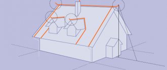
7.1.20. Electrical networks of buildings must be designed to power advertising lighting, shop windows, facades, illumination, outdoor, fire-fighting devices, dispatch systems, local television networks, light indicators of fire hydrants, safety signs, bell and other alarms, light fencing lights, etc., in in accordance with the design specifications.
7.1.21. When supplying single-phase consumers of buildings from a multiphase distribution network, it is allowed for different groups of single-phase consumers to have common N and PE conductors (five-wire network) laid directly from the ASU; combining N and PE conductors (four-wire network with PEN conductor) is not allowed.
When supplying single-phase consumers from a multiphase supply network with branches from overhead lines, when the PEN conductor of the overhead line is common to groups of single-phase consumers powered from different phases, it is recommended to provide protective shutdown of consumers when the voltage exceeds the permissible limit, arising due to load asymmetry when the PEN breaks conductor. The disconnection must be carried out at the entrance to the building, for example, by influencing the independent release of the input circuit breaker using a maximum voltage relay, and both the phase (L) and neutral working (N) conductors must be disconnected.
When choosing devices and devices installed at the input, preference, other things being equal, should be given to devices and devices that remain operational when the voltage exceeds the permissible voltage, arising due to load asymmetry when the PEN or N conductor breaks, while their switching and other performance specifications may not be met.
In all cases, it is prohibited to have switching contact and non-contact elements in PE and PEN conductor circuits.
Connections that can be disassembled with a tool are allowed, as well as connectors specially designed for this purpose.
There is no marking inside the shield
All devices and conductors within any electrical panel must be easily identifiable. Previously, white PVC tubes were used to mark conductors, on which the corresponding inscriptions were applied. Nowadays, this task has been significantly simplified - ready-made marking products are used. In Fig. Figure 4 shows a method for marking conductors inside an electrical panel. Use alphanumeric markings in accordance with the electrical diagram of the panel. The buses for connecting zero working and protective conductors are designated N and PE, respectively. For neutral working conductors, wires with blue insulation are used. For zero protective ones - with insulation containing stripes of yellow and green colors. Phase buses are designated L1, L2, L3. Regarding the color designation of phase busbars, there is currently no unambiguous solution - there is a significant inconsistency in regulatory documents, described in detail in the annotation to GOST R 50462-2009.
In accordance with the requirements of some regulatory documents, it is also necessary to mark the contact terminals of N and PE buses. The serial numbers must correspond to the serial numbers of the protection devices (see, for example, clause 6.3.10 of GOST R 51628-2000 and clause 6.4.6 of GOST R 51732-2001). But meeting this requirement, unfortunately, is often difficult to implement when using small-sized tires.
Marking of conductors in the electrical panel
Rice. 4 Marking of conductors in the electrical panel
Input devices, distribution boards, distribution points, group boards
7.1.22. A VU or ASU must be installed at the entrance to the building. One or more VU or ASU may be installed in a building.
If there are several economically separate consumers in a building, it is recommended that each of them install an independent VU or ASU.
The ASU is also allowed to supply power to consumers located in other buildings, provided that these consumers are functionally connected.
For branches from overhead lines with a rated current of up to 25 A, the VU or ASU may not be installed at the inputs to the building if the distance from the branch to the group panel, which in this case performs the functions of the VU, is no more than 3 m. This section of the network must be carried out with a flexible copper cable with with a conductor cross-section of at least 4 mm2, flame retardant, laid in a steel pipe, and the requirements for ensuring a reliable contact connection with the branch wires must be met.
For air input, surge suppressors must be installed.
7.1.23. Before entering buildings, it is not allowed to install additional cable boxes to separate the service scope of external supply networks and networks inside the building. Such separation must be carried out in the ASU or main switchboard.
7.1.24. VU, ASU, main switchboard must have protection devices on all inputs of supply lines and on all outgoing lines.
7.1.25. Control devices must be installed at the input of supply lines to the VU, ASU, and main switchboards. On outgoing lines, control devices can be installed either on each line, or be common to several lines.
A circuit breaker should be considered as a protection and control device.
7.1.26. Control devices, regardless of their presence at the beginning of the supply line, must be installed at the inputs of the supply lines in retail premises, utilities, administrative premises, etc., as well as in consumer premises that are administratively and economically isolated.
7.1.27. The floor panel must be installed at a distance of no more than 3 m along the length of the electrical wiring from the supply riser, taking into account the requirements of Chapter. 3.1.
7.1.28. VU, ASU, main switchboard, as a rule, should be installed in electrical switchboard rooms accessible only to maintenance personnel. In areas prone to flooding, they should be installed above the flood level.
VU, ASU, main switchboard can be located in rooms allocated in operational dry basements, provided that these rooms are accessible to maintenance personnel and are separated from other rooms by partitions with a fire resistance limit of at least 0.75 hours.
When placing VU, ASU, main switchboards, distribution points and group panels outside electrical switchboard rooms, they must be installed in places convenient and accessible for maintenance, in cabinets with an enclosure protection degree of at least IP31.
The distance from pipelines (water supply, heating, sewerage, internal drains), gas pipelines and gas meters to the installation site must be at least 1 m.
7.1.29. Electrical switchboard rooms, as well as VU, ASU, main switchboards, are not allowed to be located under toilets, bathrooms, showers, kitchens (except for apartment kitchens), sinks, washing and steam rooms of bathhouses and other rooms associated with wet technological processes, except in cases where Special measures have been taken for reliable waterproofing to prevent moisture from entering the premises where the switchgear is installed.
It is not recommended to lay pipelines (plumbing, heating) through electrical rooms.
Pipelines (plumbing, heating), ventilation and other ducts laid through electrical switchboard rooms should not have branches within the room (with the exception of a branch to the heating device of the switchboard room itself), as well as hatches, valves, flanges, valves, etc.
Laying gas and pipelines with flammable liquids, sewerage and internal drains through these premises is not permitted.
Doors to electrical rooms must open outward.
7.1.30. The premises in which ASUs and main switchboards are installed must have natural ventilation and electric lighting. The room temperature should not be lower than +5 oC.
7.1.31. Electrical circuits within the VU, ASU, main switchboard, distribution points, group panels should be made with wires with copper conductors.
Requirements for switchboard and distribution devices
Switchboard rooms are not allowed to be located under toilets, bathrooms, showers, kitchens, sinks, washing and steam rooms, laundry rooms, dry cleaners, etc. Pipelines and ducts laid through switchboard rooms should not have branches, hatches, valves, or flanges. The laying of gas pipelines and pipelines with flammable liquids, sewerage and internal drains through these premises is not allowed (clause 7.1.29 of the PUE). Panel doors must open outward. Switchboards must have natural ventilation and electric lighting, heating, providing a temperature not lower than +5 ° C (clause 7.1.30, PUE). Switchboard rooms must be equipped with protective equipment and first aid equipment in accordance with clause 1.1.36 of the PUE. The switchgear must have clear inscriptions indicating the purpose of individual circuits and panels on the front side of the device (clause 4.1.3 PUE). All metal parts of the switchgear must be painted (clause 4.1 PUE). The switchgear must be grounded (clause 4.1 PUE). Switching device drives must clearly indicate the “On” position. and "Off" (clause 4.1.11 PUE). The color designation of tires must comply with clause 1.1.29 of the PUE: the most distant one is yellow (A), the middle one is green (B), the closest one is red (C); in the vertical plane: A-B-C - from top to bottom or from left to right. DC buses: positive (+) - red, negative (-) - blue, zero operating (M) - blue. The most distant is M, the middle is (-), the closest is (+); in the vertical plane: M, (-), (+) from left to right or from top to bottom. A zero working tire is indicated in blue, if the same tire is used as a zero protective tire - blue along the entire length and stripes of yellow and green at the ends (clause 1.1.29 of the PUE). The color designations of the wires must comply with clause 2.1.31 of the PUE: blue - neutral working or middle conductor; green-yellow - protective or zero protective conductor; green-yellow with blue marks at the ends - combined zero working and zero protective conductor. Phase conductors: black, brown, red, purple, gray, pink, white, orange, turquoise. Apparatuses and instruments should be located so that sparks or electric arcs arising in them during operation cannot cause harm to operating personnel, ignite or damage surrounding objects, or cause a short circuit or ground fault (clause 4.1.8 of the Electrical Installation Regulations). If the input panel of a multi-panel ASU has two input blocks connected to different power supply networks, then they must be separated by a partition. A partition should also be provided between the ATS input devices (GOST R 51732-2001, clause 6.2.10). In single-panel and cabinet-mounted ASUs, input and distribution units should be separated by partitions (GOST R 51732-2001, clause 6.2.11). If one distribution panel of a multi-panel ASU contains two distribution units connected to different inputs, then a partition must be provided between them (GOST R 51732-2001, clause 6.2.12). It must be possible to relieve voltage from each switching device during its repair or dismantling. For this purpose, switches or other disconnecting devices must be installed in the required places (clause 4.1.12 of the Electrical Installation Code). Installation of instruments and devices on switchgear and low-voltage switchgears should be carried out in an area from 400 to 2000 mm from the floor level. Manual operational control devices (switches, buttons) are recommended to be installed at a height of 700 to 1900 mm from the floor level. It is recommended to install measuring instruments so that the scale of each instrument is at a height of 1000 to 1800 mm from the floor (clause 4.1.14 PUE). Between fixedly fixed non-insulated current-carrying parts, as well as between them and non-insulated non-current-carrying metal parts, distances of at least 20 mm along the insulation surface and 12 mm in the air must be provided. Distances of at least 40 mm must be provided from non-insulated live parts to the fence (clause 4.1.15 PUE). In electrical rooms, service passages located on the front or rear side of the switchboard must meet the following requirements: 1) the clear width of passages must be at least 0.8 m, the height of clear passages must be at least 1.9 m. The width of the passage must ensure comfortable maintenance of installation and movement of equipment. In some places, passages may be constrained by protruding building structures, but the width of the passage in these places must be at least 0.6 m; 2) the distances from the most protruding unfenced insulated live parts (for example, disconnected knife switches) when they are located on one side at a height of less than 2.2 m to the opposite wall, fence or equipment that does not have unfenced uninsulated live parts, must be no less than: 1.0 m - for voltages below 660 V for a board length of up to 7 and 1.2 m for board lengths of more than 7 m, 1.5 m - for voltages of 660 V and above. The length of the shield in this case is the length of the passage between two rows of a solid front of panels (cabinets) or between one row and a wall; 3) the distances between unfenced non-insulated live parts and those located at a height of less than 2.2 m when they are located on both sides must be at least: 1.5 m - for voltages below 660 V; 2 m - at voltage 660 V and above; 4) non-insulated live parts located at distances less than those given in paragraphs. 2 and 3 must be fenced. In this case, the width of the passage, taking into account the fences, must be no less than specified in paragraph 1; 5) unfenced, non-insulated live parts located above passages must be located at a height of at least 2.2 m; 6) fences placed horizontally above passages must be located at a height of at least 1.9 m; 7) passages for servicing shields with a shield length of more than 7 m must have two exits. Exits from the passage on the installation side of the switchboard can be made both into the switchboard room and into a room for other purposes. If the service passage width is more than 3 m and there are no oil-filled devices, the second exit is not necessary. Doors from switchgear rooms must open towards other rooms (with the exception of switchgears above 1 kV AC and above 1.5 kV DC) or outwards and have self-locking locks that can be unlocked without a key from the inside of the room. The width of the doors must be at least 0.75 m, height - at least 1.9 m (clause 4.1.23 PUE). Entrances to buildings must be equipped with a VU or ASU. Before entering the building, it is not allowed to install additional cable boxes to separate the service scope of external supply networks and networks inside the building. Such separation must be carried out in the ASU or main switchboard (clause 7.1.23 of the Electrical Installation Regulations). VU, ASU, main switchboard must have protection devices on all inputs of supply lines and on all outgoing lines (clause 7.1.24 PUE). Electrical circuits of VU, ASU, main switchboard, VRShch, distribution points, group panels should be made with wires with copper conductors (clause 7.1.31 PUE). After the meter, protection devices must be installed on the group lines (clause 7.1.65 of the PUE). A switching device must be installed in front of the meter to relieve voltage from all phases connected to the meter (clause 7.1.64 PUE).
Electrical wiring and cable lines
7.1.32. Internal wiring must be carried out taking into account the following:
1. Electrical installations of different organizations, separate administratively and economically, located in the same building, can be connected by branches to a common supply line or fed by separate lines from the ASU or main switchboard.
2. It is allowed to connect several risers to one line. On branches to each riser supplying apartments in residential buildings with more than 5 floors, a control device combined with a protection device should be installed.
3. In residential buildings, lamps in staircases, lobbies, halls, floor corridors and other indoor premises outside apartments must be powered via independent lines from the ASU or separate group panels powered from the ASU. Connecting these lamps to floor and apartment panels is not allowed.
4. For staircases and corridors with natural light, it is recommended to provide automatic control of electric lighting depending on the illumination created by natural light.
5. It is recommended to supply power to electrical installations of non-residential buildings using separate lines.
7.1.33. Supply networks from substations to VU, ASU, main switchboard must be protected from short-circuit currents.
7.1.34. Cables and wires with copper conductors should be used in buildings
Supply and distribution networks, as a rule, must be made of cables and wires with aluminum conductors if their design cross-section is 16 mm2 or more.
The power supply of individual electrical receivers related to the engineering equipment of buildings (pumps, fans, heaters, air conditioning units, etc.) can be provided by wires or cables with aluminum conductors with a cross-section of at least 2.5 mm2.
In museums, art galleries, and exhibition spaces, it is permitted to use lighting busbar trunking systems with a degree of protection IP20, in which the branch devices to the lamps have detachable contact connections located inside the busbar trunking box at the time of switching, and busbar trunking systems with a degree of protection IP44, in which the branching devices to the lamps are made with using plug connectors that ensure the branch circuit is broken until the plug is removed from the socket.
In these premises, lighting busbars must be powered from distribution points by independent lines.
In residential buildings, the cross-sections of copper conductors must correspond to the calculated values, but not be less than those indicated in Table 7.1.1.
1 Until 2001, according to the existing construction backlog, the use of wires and cables with aluminum conductors was allowed.
Table 7.1.1. The smallest permissible cross-sections of cables and wires of electrical networks in residential buildings.
| Line names | Smallest cross-section of cables and wires with copper conductors, mm2 |
| Group network lines | 1,5 |
| Lines from floor to apartment panels and to the settlement meter | 2,5 |
| Distribution network lines (risers) for supplying apartments | 4 |
7.1.35. In residential buildings, laying vertical sections of the distribution network inside apartments is not allowed.
It is prohibited to lay wires and cables from the floor panel in a common pipe, common box or channel that supply lines to different apartments.
Fire-retardant installation in a common pipe, common box or channel of building structures made of non-combustible materials, wires and cables of apartment supply lines together with wires and cables of group lines of working lighting of staircases, floor-by-floor corridors and other indoor premises is allowed.
7.1.36. In all buildings, group network lines laid from group, floor and apartment switchboards to general lighting fixtures, plug sockets and stationary electrical receivers must be three-wire (phase - L, neutral working - N and neutral protective - PE conductors).
Combining zero working and zero protective conductors of different group lines is not allowed.
The neutral working and neutral protective conductors are not allowed to be connected on panels under a common contact terminal.
Conductor cross-sections must meet the requirements of clause 7.1.45.
7.1.37. Electrical wiring in the premises should be replaced: hidden - in the channels of building structures, embedded pipes; open - in electrical skirting boards, boxes, etc.
In technical floors, undergrounds, unheated basements, attics, ventilation chambers, damp and especially damp rooms, it is recommended that electrical wiring be carried out openly.
In buildings with building structures made of non-combustible materials, permanent, monolithic installation of group networks is allowed in the grooves of walls, partitions, ceilings, under plaster, in the floor preparation layer or in the voids of building structures, carried out with cable or insulated wires in a protective sheath. The use of permanently embedded wiring in panels of walls, partitions and ceilings, made during their manufacture at construction industry factories or carried out in the mounting joints of panels during the installation of buildings, is not allowed.
7.1.38. Electrical networks laid behind impenetrable suspended ceilings and in partitions are considered as hidden electrical wiring and should be installed: behind ceilings and in the voids of partitions made of flammable materials in metal pipes with localization capabilities and in closed boxes; behind ceilings and in partitions made of non-combustible materials 2 - in pipes and ducts made of non-flammable materials, as well as flame retardant cables. In this case, it must be possible to replace wires and cables.
2 Suspended ceilings made of non-combustible materials mean those ceilings that are made of non-combustible materials, while other building structures located above suspended ceilings, including interfloor ceilings, are also made of non-combustible materials.
7.1.39. In rooms for cooking and eating, with the exception of apartment kitchens, open laying of cables is allowed. Open wiring of wires in these rooms is not allowed.
In apartment kitchens, the same types of electrical wiring can be used as in living rooms and corridors.
7.1.40. In saunas, bathrooms, toilets, showers, as a rule, hidden electrical wiring should be used. Open cable routing is allowed.
In saunas, bathrooms, toilets, showers, laying wires with metal sheaths, in metal pipes and metal sleeves is not allowed.
In saunas for zones 3 and 4 according to GOST R 50571.12-96 “Electrical installations of buildings. Part 7. Requirements for special electrical installations. Section 703: Premises Containing Sauna Heaters" electrical wiring with an insulation temperature rating of 170oC must be used.
7.1.41. Electrical wiring in attics must be carried out in accordance with the requirements of Section. 2.
7.1.42. Through the basements and technical undergrounds of sections of the building, it is allowed to lay power cables with a voltage of up to 1 kV, supplying electrical receivers of other sections of the building. The specified cables are not considered as transit; laying transit cables through basements and technical undergrounds of buildings is prohibited.
7.1.43. Open laying of transit cables and wires through storerooms and warehouses is not permitted.
7.1.44. The lines supplying refrigeration units of trade and public catering enterprises must be laid from the ASU or main switchboard of these enterprises.
7.1.45. The selection of conductor cross-sections should be carried out in accordance with the requirements of the relevant chapters of the PUE.
Single-phase two- and three-wire lines, as well as three-phase four- and five-wire lines when supplying single-phase loads, must have a cross-section of zero working (N) conductors equal to the cross-section of phase conductors.
Three-phase four- and five-wire lines when supplying three-phase symmetrical loads must have a cross-section of zero working (N) conductors equal to the cross-section of phase conductors, if the phase conductors have a cross-section of up to 16 mm2 for copper and 25 mm2 for aluminum, and for large cross-sections - at least 50 % cross-section of phase conductors.
The cross-section of PEN conductors must be at least the cross-section of N conductors and at least 10 mm2 for copper and 16 mm2 for aluminum, regardless of the cross-section of the phase conductors.
The cross-section of PE conductors must be equal to the cross-section of phase conductors with a cross-section of the latter up to 16 mm2, 16 mm2 with a cross-section of phase conductors from 16 to 35 mm2 and 50% of the cross-section of phase conductors with larger cross-sections.
The cross-section of PE conductors not included in the cable must be at least 2.5 mm2 - in the presence of mechanical protection and 4 mm2 - in its absence.
Requirements for electrical panels (PUE, SP, SanPiN, SNiP)
In electrical rooms (see 1.1.5.), service passages located on the front or rear side of the switchboard must meet the following requirements:1) the clear width of passages must be at least 0.8 m, the height of clear passages must be at least 1.9 m. The width of the passage must ensure convenient maintenance of the installation and movement of equipment. In some places, passages may be constrained by protruding building structures, but the width of the passage in these places must be at least 0.6 m;
2) the distances from the most protruding unfenced uninsulated live parts (for example, disconnected knife switches) when they are located on one side at a height of less than 2.2 m to the opposite wall, fence or equipment that does not have unfenced uninsulated live parts, must be at least:
- 1.0 m - for voltages below 660 V for a shield length of up to 7 and 1.2 m for a shield length of more than 7 m; 1.5 m - at voltage 660 V and above.
— The length of the shield in this case is the length of the passage between two rows of the solid front of panels (cabinets) or between one row and the wall;
3) the distances between unfenced uninsulated live parts and those located at a height of less than 2.2 m when they are located on both sides must be no less than:
— 1.5 m — at voltage below 660 V; 2.0 m - at voltage 660 V and above;
4) non-insulated live parts located at distances less than those given in paragraphs 2 and 3 must be fenced. In this case, the width of the passage, taking into account the fences, must be no less than specified in paragraph 1;
5) unprotected, uninsulated live parts located above passages must be located at a height of at least 2.2 m;
6) fences placed horizontally above passages must be located at a height of at least 1.9 m;
7) passages for servicing shields with a shield length of more than 7 m must have two exits. Exits from the passage on the installation side of the switchboard can be made both into the switchboard room and into rooms for other purposes. If the service passage width is more than 3 m and there are no oil-filled devices, the second exit is not necessary. Doors from switchgear rooms must open towards other rooms (with the exception of switchgears above 1 kV AC and above 1.5 kV DC) or outwards and have self-locking locks that can be unlocked without a key from the inside of the room. The width of the doors must be at least 0.75 m, height at least 1.9 m.
Internal electrical equipment
7.1.46. In food preparation rooms, except for apartment kitchens, lamps with incandescent lamps installed above workplaces (stoves, tables, etc.) must have protective glass underneath. Lamps with fluorescent lamps must have grilles or grids or lamp holders that prevent the lamps from falling out.
7.1.47. In bathrooms, showers and lavatories, only electrical equipment should be used that is specifically designed for installation in the relevant areas of these premises in accordance with GOST R 50571.11-96 “Electrical installations of buildings. Part 7. Requirements for special electrical installations. Section 701 - Bathrooms and Shower Facilities" and the following requirements must be met:
- — electrical equipment must have a degree of protection against water not lower than: in zone 0 — IPx7;
- in zone 1 - IPx5;
- in zone 2 - IPx4 (IPx5 - in public baths);
- in zone 3 - IPx1 (IPx5 - in public baths);
- — in zone 1 only water heaters can be installed;
7.1.48. Installation of plug sockets in bathrooms, showers, soap rooms of baths, rooms containing heaters for saunas (hereinafter referred to as “saunas”), as well as in washing rooms of laundries is not allowed, with the exception of bathrooms in apartments and hotel rooms.
In the bathrooms of apartments and hotel rooms, it is allowed to install plug sockets in zone 3 in accordance with GOST R 50571.11-96, connected to the network through isolation transformers or protected by a residual current device that responds to a differential current not exceeding 30 mA.
Any switches and sockets must be located at a distance of at least 0.6 m from the doorway of the shower stall.
7.1.49. In buildings with a three-wire network (see clause 7.1.36.), plug sockets with a current of at least 10 A with a protective contact must be installed.
Plug sockets installed in apartments, living rooms in dormitories, as well as in rooms for children in child care institutions (kindergartens, nurseries, schools, etc.) must have a protective device that automatically closes the sockets of the socket when the plug is removed.
7.1.50. The minimum distance from switches, sockets and electrical installation elements to gas pipelines must be at least 0.5 m.
7.1.51. It is recommended to install switches on the wall on the side of the door handle at a height of up to 1 m; they can be installed under the ceiling with control using a cord.
In rooms for children in children's institutions (kindergartens, nurseries, schools, etc.), switches should be installed at a height of 1.8 m from the floor.
7.1.52. In saunas, bathrooms, toilets, soap rooms, steam rooms, washing rooms, laundries, etc. installation of switchgear and control devices is not permitted.
In washbasin rooms and zones 1 and 2 (GOST R 50571.11-96) of bathrooms and shower rooms, it is allowed to install switches operated by a cord.
7.1.53. Switching devices for lighting networks in attics that have building structure elements (roofing, trusses, rafters, beams, etc.) made of flammable materials must be installed outside the attic.
7.1.54. Switches for work lamps, safety and evacuation lighting of premises intended for the presence of a large number of people (for example, retail premises of shops, canteens, hotel lobbies, etc.) must be accessible only to service personnel.
7.1.55. A lamp should be installed above each entrance to the building.
7.1.56. House license plates and fire hydrant signs installed on exterior walls of buildings must be illuminated. Electric light sources for license plates and hydrant indicators must be powered from the internal lighting network of the building, and fire hydrant indicators installed on external lighting poles must be powered from the external lighting network.
7.1.57. Fire safety devices and security alarms, regardless of the category of reliability of the building's power supply, must be powered from two inputs, and in their absence, by two lines from one input. Switching from one line to another should be automatic.
7.1.58. Electric motors, distribution points, separately installed switching devices and protective devices installed in the attic must have a degree of protection of at least IP44.
Regulatory requirements for the design of electrical panels
[1.4] 6.1.6.1 In electrical rooms, service passages located on the front or rear side of the switchboard must meet the following requirements:
1) the clear width of passages must be at least 0.8 m, the height of clear passages must be at least 1.9 m. The width of the passage must ensure convenient maintenance of the installation and movement of equipment.
In some places, passages may be constrained by protruding building structures, but the width of the passage in these places must be at least 0.6 m;
2) the distances from the most protruding unfenced uninsulated live parts (for example, disconnected knife switches) when they are located on one side at a height of less than 2.2 m to the opposite wall, fence or equipment that does not have unfenced uninsulated live parts, must be at least:
− 1.0 m − for voltages below 660 V for a shield length of up to 7 and 1.2 m for a shield length of more than 7 m;
− 1.5 m − at voltage 660 V and above.
The length of the shield in this case is the length of the passage between two rows of a solid front of panels (cabinets) or between one row and a wall;
3) the distances between unfenced uninsulated live parts and those located at a height of less than 2.2 m when they are located on both sides must be no less than:
− 1.5 m − at voltage below 660 V;
− 2.0 m − at voltage 660 V and above.
4) non-insulated live parts located at distances less than those given in 2) and 3) must be fenced.
In this case, the width of the passage, taking into account the fences, must be no less than specified in 6.1.6.1 1);
5) unprotected, uninsulated live parts located above passages must be located at a height of at least 2.2 m;
6) fences placed horizontally above passages must be located at a height of at least 1.9 m;
7) passages for servicing panels, with a panel length of more than 7 m, must have two exits. Exits from the passage on the installation side of the switchboard can be made both into the switchboard room and into rooms for other purposes. If the service passage width is more than 3 m and there are no oil-filled devices, the second exit is not necessary. Doors from switchgear rooms must open towards other rooms (with the exception of switchgears above 1 kV AC and above 1.5 kV DC) or outwards and have self-locking locks that can be unlocked without a key from the inside of the room. The width of the doors must be at least 0.75 m, height - at least 1.9 m.
[2.3] 4.1.23. In electrical rooms (see 1.1.5.), service passages located on the front or rear side of the switchboard must meet the following requirements:
1) the clear width of passages must be at least 0.8 m, the height of clear passages must be at least 1.9 m. The width of the passage must ensure convenient maintenance of the installation and movement of equipment. In some places, passages may be constrained by protruding building structures, but the width of the passage in these places must be at least 0.6 m;
2) the distances from the most protruding unfenced uninsulated live parts (for example, disconnected knife switches) when they are located on one side at a height of less than 2.2 m to the opposite wall, fence or equipment that does not have unfenced uninsulated live parts, must be at least:
1.0 m - for voltages below 660 V for a shield length of up to 7 and 1.2 m for a shield length of more than 7 m;
1.5 m - at voltage 660 V and above.
The length of the shield in this case is the length of the passage between two rows of a solid front of panels (cabinets) or between one row and a wall;
3) the distances between unfenced uninsulated live parts and those located at a height of less than 2.2 m when they are located on both sides must be no less than:
1.5 m - at voltage below 660 V;
2.0 m - at voltage 660 V and above;
4) non-insulated live parts located at distances less than those given in paragraphs. 2 and 3 must be fenced. In this case, the width of the passage, taking into account the fences, must be no less than specified in paragraph 1;
5) unprotected, uninsulated live parts located above passages must be located at a height of at least 2.2 m;
6) fences placed horizontally above passages must be located at a height of at least 1.9 m;
7) passages for servicing shields with a shield length of more than 7 m must have two exits. Exits from the passage on the installation side of the switchboard can be made both into the switchboard room and into rooms for other purposes. If the service passage width is more than 3 m and there are no oil-filled devices, the second exit is not necessary. Doors from switchgear rooms must open towards other rooms (with the exception of switchgears above 1 kV AC and above 1.5 kV DC) or outwards and have self-locking locks that can be unlocked without a key from the inside of the room. The width of the doors must be at least 0.75 m, height at least 1.9 m.
Electricity metering
7.1.59. In residential buildings, one single- or three-phase billing meter (with three-phase input) should be installed for each apartment.
7.1.60. Calculation meters in public buildings that house several electricity consumers must be provided for each consumer, isolated in administrative and economic terms (studio, shops, workshops, warehouses, housing maintenance offices, etc.).
7.1.61. In public buildings, estimated electricity meters must be installed on the ASU (main switchboard) at the points of balance demarcation with the energy supply organization. If there are built-in or attached transformer substations, the power of which is fully used by consumers of a given building, the calculated meters should be installed at the low-voltage terminals of power transformers on combined low-voltage switchboards, which are also the building’s ASU.
ASU and metering devices for different subscribers located in the same building may be installed in one common room. By agreement with the energy supplying organization, settlement meters can be installed at one of the consumers, from which the ASU supplies other consumers located in the building. At the same time, control meters should be installed at the inputs of the supply lines in the premises of these other consumers for settlements with the main subscriber.
7.1.62. Estimated meters for the general house load of residential buildings (lighting of staircases, building management offices, yard lighting, etc.) are recommended to be installed in ASU cabinets or on main switchboard panels.
7.1.63. It is recommended to place residential meters together with protection devices (circuit breakers, fuses).
When installing apartment panels in the hallways of apartments, meters, as a rule, should be installed on these panels; installation of meters on floor panels is allowed.
7.1.64. To safely replace a meter directly connected to the network, a switching device must be provided in front of each meter to remove voltage from all phases connected to the meter.
Disconnecting devices for removing voltage from settlement meters located in apartments must be located outside the apartment.
7.1.65. After the meter connected directly to the network, a protection device must be installed. If several lines equipped with protection devices extend after the meter, installation of a common protection device is not required.
7.1.66. It is recommended to equip residential buildings with remote meter reading systems.